1
A
MP+ 1.90 - 1.110
it
CALDAIA MURALE A GAS A CONDENSAZIONE
Manuale per l’uso destinato all’utente e all’installatore
en
CONDENSING GAS WALL-HUNG BOILERS
Instructions manual for users and fitters
de(AT)
KONDENSATIONS-WANDGASHEIZKESSEL
Gebrauchsanleitung für den Benutzer und Installateur
es
CALDERA MURAL DE GAS A CONDENSACIÓN
Manual de uso destinado al usuario y al instalador
Gentile Cliente,
la nostra Azienda ritiene che il Suo nuovo prodotto soddisferà tutte le Sue esigenze. L’acquisto di un nostro prodotto garantisce
quanto Lei si aspetta: un buon funzionamento ed un uso semplice e razionale.
Quello che Le chiediamo è di non mettere da parte queste istruzioni senza averle prima lette: esse contengono informazioni utili
per una corretta ed efficiente gestione della Suo prodotto.
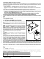
La nostra azienda dichiara che questi prodotti sono dotati di marcatura
delle seguenti Direttive:
- - - - conformemente ai requisiti essenziali
Direttiva Gas 2009/142/CE
Direttiva Compatibilità Elettromagnetica 2004/108/CE
Direttiva Bassa tensione 2006/95/CE
Direttiva progettazione ecocompatibile 2009/125/CE
Regolamento (UE) N. 813/2013 - 811/2013
Utente & Installatore (it)
La nostra azienda, nella costante azione di miglioramento dei prodotti, si riserva la possibilità di modificare i dati espressi in
questa documentazione in qualsiasi momento e senza preavviso. La presente documentazione è un supporto informativo e
non considerabile come contratto nei confronti di terzi.
L’apparecchio può essere utilizzato da bambini di età non inferiore a 8 anni e da
persone con ridotte capacità fisiche, sensoriali o mentali, o prive di esperienza o
della necessaria conoscenza, purché sotto sorveglianza oppure dopo che le stesse
abbiano ricevuto istruzioni relative all’uso sicuro dell’apparecchio e alla comprensione dei pericoli ad esso inerenti. I bambini non devono giocare con l’apparecchio. La pulizia e la manutenzione destinata ad essere effettuata dall’utilizzatore
non deve essere effettuata da bambini senza sorveglianza.
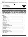
SOMMARIO
DESCRIZIONE SIMBOLI...............................................................................................................................................................................3
AVVERTENZE DI SICUREZZA......................................................................................................................................................................3
AVVERTENZE GENERALI ...........................................................................................................................................................................4
CONSIGLI PER IL RISPARMIO ENERGETICO............................................................................................................................................4
1.
MESSA IN FUNZIONE DELLA CALDAIA......................................................................................................................................................5
1.1 REGOLAZIONE DELLA TEMPERATURA DI MANDATA RISCALDAMENTO E DELL'ACQUA SANITARIA.................................................5
1.2 MODI DI FUNZIONAMENTO.........................................................................................................................................................................5
2.
ARRESTO PROLUNGATO IMPIANTO E PROTEZIONE ANTIGELO...........................................................................................................6
3.
CAMBIO GAS................................................................................................................................................................................................6
4.ANOMALIE.....................................................................................................................................................................................................6
5.
MENU INFORMAZIONI DI CALDAIA.............................................................................................................................................................7
6.
RIEMPIMENTO IMPIANTO............................................................................................................................................................................7
7.
ISTRUZIONI PER L'ORDINARIA MANUTENZIONE.....................................................................................................................................7
8.
SPEGNIMENTO DELLA CALDAIA................................................................................................................................................................7
AVVERTENZE PRIMA DELL'INSTALLAZIONE.............................................................................................................................................8
9.
INSTALLAZIONE DELLA CALDAIA...............................................................................................................................................................8
9.1 POMPA DI CALDAIA......................................................................................................................................................................................8
10. INSTALLAZIONE DEI CONDOTTI.................................................................................................................................................................9
10.1 CONDOTTI COASSIALI...............................................................................................................................................................................9
10.2 CONDOTTI SEPARATI.................................................................................................................................................................................9
10.3 CONDOTTI IN CASCATA..............................................................................................................................................................................10
11.
COLLEGAMENTI ELETTRICI........................................................................................................................................................................10
11.1 COLLEGAMENTO TERMOSTATO AMBIENTE.............................................................................................................................................11
11.2 ACCESSORI NON INCLUSI NELLA DOTAZIONE........................................................................................................................................11
IMPOSTAZIONE PARAMETRI MEDIANTE IL CONTROLLO REMOTO.......................................................................................................12
11.3 COLLEGAMENTO SICUREZZE INAIL..........................................................................................................................................................14
12. PRIMA ACCENSIONE - FUNZIONI SPECIALI..............................................................................................................................................14
12.1 FUNZIONE DEGASAMENTO IMPIANTO......................................................................................................................................................14
12.2 FUNZIONE TARATURA.................................................................................................................................................................................14
12.3 FUNZIONE SPAZZACAMINO........................................................................................................................................................................14
13. ANOMALIE NON RESETTABILI DALL'UTENTE...........................................................................................................................................14
14. IMPOSTAZIONE PARAMETRI.......................................................................................................................................................................15
15. TARATURA VALVOLA GAS...........................................................................................................................................................................17
15.1 CAMBIO GAS................................................................................................................................................................................................17
16. DISPOSITIVI DI REGOLAZIONE E SICUREZZA..........................................................................................................................................18
17. CARATTERISTICHE PORTATA/PREVALENZA ALLA PLACCA....................................................................................................................18
18.
MANUTENZIONE ANNUALE.........................................................................................................................................................................19
18.1 PULIZIA DEL SIFONE DI SCARICO CONDENSA........................................................................................................................................19
18.2 PULIZIA DELLO SCAMBIATORE LATO FUMI..............................................................................................................................................19
18.3 CONTROLLO DEL BRUCIATORE.................................................................................................................................................................20
18.4 PARAMETRI DI COMBUSTIONE..................................................................................................................................................................20
19. SOSTITUZIONE DEL TERMOFUSIBILE DELLO SCAMBIATORE...............................................................................................................21
20. DISINSTALLAZIONE, SMALTIMENTO E RICICLAGGIO..............................................................................................................................21
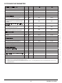
21. CARATTERISTICHE TECNICHE...................................................................................................................................................................22
22. PARAMETRI TECNICI...................................................................................................................................................................................23
23. SCHEDA PRODOTTO...................................................................................................................................................................................24
7221409.01 (1-03/15)
2
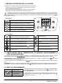
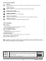
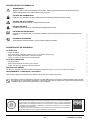
DESCRIZIONE SIMBOLI
AVVERTENZA
Rischio di danno o di malfunzionamento dell'apparecchio. Prestare particolare attenzione alle avvertenze
di pericolo che riguardano possibili danni alle persone. PERICOLO SCOTTATURE
Attendere che l'apparecchio si raffreddi prima di agire sulle parti esposte al calore.
PERICOLO ALTA TENSIONE
Parti elettriche in tensione, pericolo di shock elettrico.
PERICOLO GELO
Probabile formazione di ghiaccio a causa di basse temperature.
DIVIETO GENERICO
Vietato effettuare/utilizzare quanto specificato a fianco del simbolo.
AVVERTENZE DI SICUREZZA
ODORE DI GAS
•
•
•
•
Spegnere la caldaia.
Non azionare alcun dispositivo elettrico (come accendere la luce).
Spegnere eventuali fiamme libere e aprire le finestre.
Chiamare il centro di Assistenza Tecnico Autorizzato.
ODORE DI COMBUSTIONE
• Spegnere la caldaia.
• Aerare il locale aprendo porte e finestre.
• Chiamare il Centro di Assistenza Tecnica Autorizzato.
MATERIALE INFIAMMABILE
Non utilizzare e/o depositare materiali facilmente infiammabili (diluenti, carta, ecc.) nelle vicinanze della caldaia.
MANUTENZIONE E PULIZIA CALDAIA
Togliere l'alimentazione elettrica alla caldaia prima di effettuare un qualsiasi intervento.
L’apparecchio non è destinato a essere usato da persone le cui capacità fisiche, sensoriali o mentali siano ridotte, oppure
con mancanza di esperienza o di conoscenza, a meno che esse abbiano potuto beneficiare, attraverso l’intermediazione di
una persona responsabile della loro sicurezza, di una sorveglianza o di istruzioni riguardanti l’uso dell’apparecchio.
BAXI tra i leader in Europa nella produzione di caldaie e sistemi per il riscaldamento ad alta
tecnologia, è certificata da CSQ per i sistemi di gestione per la qualità (ISO 9001) per l’ambiente
(ISO 14001) e per la salute e sicurezza (OHSAS 18001). Questo attesta che BAXI S.p.A. riconosce
come propri obiettivi strategici la salvaguardia dell’ambiente, l’affidabilità e la qualità dei propri
prodotti, la salute e sicurezza dei propri dipendenti.
L’azienda attraverso la propria organizzazione è costantemente impegnata a implementare e
migliorare tali aspetti a favore della soddisfazione dei propri clienti.
3
7221409.01 (1-03/15)
Utente & Installatore (it)
INFORMAZIONI IMPORTANTI
Informazioni da leggere con particolare attenzione perchè utili al corretto funzionamento della caldaia.
AVVERTENZE GENERALI
Questa caldaia serve a riscaldare l’acqua ad una temperatura inferiore a quella di ebollizione a pressione atmosferica. Essa deve
essere allacciata ad un impianto di riscaldamento e ad una rete di distribuzione di acqua calda sanitaria, compatibilmente alle sue
prestazioni ed alla sua potenza. Prima di far allacciare la caldaia da personale professionalmente qualificato, secondo il DM n°
37 del 22.01.08, far effettuare:
• Una verifica che la caldaia sia predisposta per il funzionamento con il tipo di gas disponibile. Questo è rilevabile dalla scritta
sull’imballo e dalla targa presente sull’apparecchio. • Un controllo che il camino abbia un tiraggio adeguato, non presenti strozzature e non siano inseriti nella canna fumaria scarichi
di altri apparecchi, salvo che questa non sia realizzata per servire più utenze secondo le specifiche Norme e prescrizioni
vigenti.
• Un controllo che, nel caso di raccordi su canne fumarie preesistenti, queste siano state perfettamente pulite poiché le scorie,
staccandosi dalle pareti durante il funzionamento, potrebbero occludere il passaggio dei fumi.
• Risulta inoltre indispensabile, al fine di preservare il corretto funzionamento e la garanzia dell’apparecchio, seguire le
precauzioni di seguito riportate.
1. Circuito sanitario
1.1 Se la durezza dell’acqua supera il valore di 20 °F (1 °F = 10 mg di carbonato di calcio per litro d’acqua) si prescrive l’installazione
di un dosatore di polifosfati o di un sistema di pari effetto rispondente alle normative vigenti.
Utente & Installatore (it)
1.2 E’ necessario effettuare un lavaggio accurato dell’impianto dopo l’installazione dell’apparecchio e prima del suo utilizzo.
1.3 I materiali utilizzati per il circuito acqua sanitaria sono conformi alla Direttiva 98/83/CE.
2. Circuito di riscaldamento
2.1 Impianto nuovo: Prima di procedere all’installazione della caldaia l’impianto deve essere opportunamente pulito allo scopo
di eliminare residui di filettature, saldature ed eventuali solventi utilizzando prodotti idonei disponibili sul mercato non acidi e non
alcalini, che non attacchino i metalli, le parti in plastica e gomma. Per la protezione dell’impianto dalle incrostazioni è necessario
l’utilizzo di prodotti inibitori quali SENTINEL X100 e FERNOX protettivo per impianti di riscaldamento. Per l’utilizzo di questi
prodotti seguire attentamente le istruzioni fornite con i prodotti stessi.
2.2 Impianto esistente: Prima di procedere all’installazione della caldaia l’impianto deve essere completamente svuotato ed
opportunamente pulito da fanghi e contaminanti utilizzando prodotti idonei disponibili sul mercato. I prodotti raccomandati per
la pulizia sono: SENTINEL X300 o X400 e FERNOX rigeneratore per impianti di riscaldamento. Per l’utilizzo di questi prodotti
seguire attentamente le istruzioni fornite con i prodotti stessi. Ricordiamo che la presenza di depositi nell’impianto di riscaldamento
comporta dei problemi funzionali alla caldaia (es. surriscaldamento e rumorosità dello scambiatore)
La prima accensione deve essere effettuata dal Servizio di Assistenza Tecnica autorizzato che dovrà verificare:
• Che i dati di targa siano rispondenti a quelli delle reti di alimentazione (elettrica, idrica, gas).
• Che l’installazione sia conforme alle normative vigenti, in particolare: UNI-CIG 7129, 7131, Regolamento di Attuazione della
Legge n° 10 del 9.01.1991 ed in specie i Regolamenti Comunali.
• Che sia stato effettuato regolarmente il collegamento alla rete elettrica provvista di messa a terra.
L'apparecchio deve essere installato in un locale aerato adibito a sala termica secondo le norme vigenti (apparecchi con
portata termica > 40 kW).
La mancata osservazione di queste avvertenze comporta il decadimento della garanzia dell’apparecchio. I nominativi dei
Centri di Assistenza Tecnica autorizzati sono rilevabili dal foglio allegato. Prima della messa in funzione togliere il film
protettivo della caldaia. Non utilizzare per lo scopo utensili o materiali abrasivi perché potrebbero danneggiare le parti
verniciate.
Le parti dell’imballo (sacchetti in plastica, polistirolo ecc.) non devono essere lasciate alla portata dei bambini in quanto
potenziali fonti di pericolo.
CONSIGLI PER IL RISPARMIO ENERGETICO
Regolazione del riscaldamento
Regolare la temperatura di mandata caldaia in funzione del tipo di impianto. Per impianti con termosifoni, si consiglia di impostare
una temperatura massima di mandata dell'acqua di riscaldamento di circa 60°C, aumentare tale valore qualora non si dovesse
raggiungere il comfort ambiente richiesto. Nel caso di impianto con pannelli radianti a pavimento, non superare la temperatura
prevista dal progettista dell'impianto. È consigliabile l’utilizzo della Sonda Esterna e/o del Pannello di Controllo per adattare
automaticamente la temperatura di mandata in funzione delle condizioni atmosferiche o della temperatura interna. In questo modo
non viene prodotto più calore di quello che è effettivamente necessario. Regolare la temperatura ambiente senza surriscaldare i
locali. Ogni grado in eccesso comporta un consumo energetico maggiore, pari a circa il 6%. Adeguare la temperatura ambiente
anche in funzione del tipo di utilizzo dei locali. Ad esempio, la camera da letto o le stanze meno usate possono essere riscaldate
ad una temperatura inferiore. Utilizzare la programmazione oraria ed impostare la temperatura ambiente nelle ore notturne
inferiore a quella nelle ore diurne di circa 5°C. Un valore più basso non conviene in termini di risparmio economico. Solo in caso
di assenza prolungata, come ad esempio una vacanza, abbassare ulteriormente il set di temperatura. Non coprire i radiatori per
evitare la corretta circolazione dell’aria. Non lasciare le finestre socchiuse per aerare i locali, ma aprire le completamente per un
breve periodo.
Acqua calda sanitaria
Un buon risparmio si ottiene impostando la temperatura sanitaria dell’acqua desiderata evitando di miscelarla con l’acqua fredda.
Ogni ulteriore riscaldamento causa uno spreco di energia e una maggiore creazione del calcare.
7221409.01 (1-03/15)
4
1. MESSA IN FUNZIONE DELLA CALDAIA
Procedere come di seguito descritto per le corrette operazioni di accensione:
•
•
•
•
Verificare che la pressione dell'impianto sia quella prescritta (capitolo 6);
Alimentare elettricamente la caldaia.
Aprire il rubinetto del gas (di colore giallo, posizionato sotto la caldaia);
Selezionare la modalità di riscaldamento desiderata (capitolo 1.2).
In fase di prima accensione, finché non viene scaricata l’aria contenuta nella tubazione del gas, si può verificare la non
accensione del bruciatore ed il conseguente blocco della caldaia. Si consiglia, in questo caso, di ripetere le operazioni
di accensione fino all’arrivo del gas al bruciatore. Per ripristinare il funzionamento della caldaia, premere il tasto per
almeno 2 secondi.
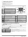
Legenda TASTI
Regolazione temperatura acqua sanitaria
(tasto + per aumentare la temperatura e tasto – per diminuirla)
Regolazione temperatura acqua di riscaldamento
(tasto + per aumentare la temperatura e tasto – per diminuirla)
Informazioni di funzionamento caldaia
Sanitario – Sanitario & Riscaldamento – Solo Riscaldamento
Spento – Reset – Uscita menu/funzioni
Legenda SIMBOLI
Spento: riscaldamento e sanitario disabilitati
(è attiva solo la protezione antigelo di caldaia)
Bruciatore acceso
Anomalia che impedisce l’accensione del bruciatore
Modo di funzionamento in sanitario abilitato
Pressione acqua caldaia/impianto bassa
Modo di funzionamento in riscaldamento
abilitato
Richiesto intervento Assistenza Tecnica
Menu di programmazione
Anomalia resettabile manualmente (tasto
Menu informazioni di caldaia
)
Anomalia in corso
Unità di misura impostate (SI/US)
1.1 REGOLAZIONE DELLA TEMPERATURA DI MANDATA RISCALDAMENTO E
DELL'ACQUA SANITARIA
La regolazione della temperatura di mandata riscaldamento e dell'acqua sanitaria (in presenza di bollitore esterno) si effettua
agendo rispettivamente sui tasti e . L’accensione del bruciatore è visualizzata sul display con il simbolo .
RISCALDAMENTO: durante il funzionamento della caldaia in riscaldamento, sul display è visualizzato il simbolo e la temperatura di mandata riscaldamento (°C).
In caso di collegamento di una Sonda Esterna, i tasti 20°C). intermittente
regolano indirettamente la temperatura ambiente (valore di fabbrica
SANITARIO: la produzione di acqua calda sanitaria è possibile collegando un bollitore esterno alla caldaia. Durante il funzionamento
della caldaia in sanitario, sul display è visualizzato il simbolo intermittente e la temperatura di mandata riscaldamento (°C).
1.2 MODI DI FUNZIONAMENTO
SIMBOLO
VISUALIZZATO
MODO DI
FUNZIONAMENTO
SANITARIO
SANITARIO &
RISCALDAMENTO
SOLO RISCALDAMENTO
Per abilitare il funzionamento dell’apparecchio in Sanitario - Riscaldamento o
Solo Riscaldamento premere ripetutamente il tasto
e scegliere una delle
tre modalità disponibili.
Per disabilitare i modi di funzionamento della caldaia mantenendo attiva la
funzione antigelo, premere il tasto ,sul display apparirà solo il simbolo (con caldaia non in blocco).
5
7221409.01 (1-03/15)
Sezione UTENTE (it)
Modo di funzionamento:
2. ARRESTO PROLUNGATO IMPIANTO E PROTEZIONE ANTIGELO
E’ buona norma evitare lo svuotamento dell’intero impianto di riscaldamento poiché ricambi d’acqua possono causare inutili e
dannosi depositi di calcare all’interno della caldaia e dei corpi scaldanti. Se durante l’inverno l’impianto termico non dovesse
essere utilizzato, nel caso di pericolo di gelo, è consigliabile miscelare l’acqua dell’impianto con idonee soluzioni anticongelanti
destinate a tale uso specifico (es. glicole propilenico associato ad inibitori di incrostazioni e corrosioni). La gestione elettronica
della caldaia è provvista di una funzione “antigelo” in riscaldamento che con temperatura di mandata impianto inferiore ai 5 °C fa
accendere il bruciatore fino al raggiungimento in mandata di un valore pari a 30 °C.
La funzione è operativa se la caldaia è alimentata elettricamente, c’è gas, la pressione dell’impianto è quella prescritta e la
caldaia non è in blocco.
3. CAMBIO GAS
Le caldaie possono funzionare sia a gas metano (G20) che a gas GPL (G31). Nel caso in cui si renda necessario il cambio gas
ci si dovrà rivolgere al SERVIZIO DI ASSISTENZA TECNICA AUTORIZZATO.
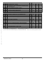
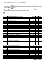
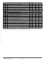
4.ANOMALIE
Le anomalie visualizzate sul display sono identificate dal simbolo Per la lista completa delle anomalie vedere la tabella seguente.
e da un numero (codice di anomalia).
Sezione UTENTE (it)
Se sul display appare il simbolo l'anomalia richiede un RESET da parte dell'utente.
Per RESETTARE la caldaia, premere il tasto . In caso d’intervento di frequenti visualizzazioni di
anomalia, chiamare il centro di Assistenza Tecnica autorizzato.
Descrizione anomalia
Descrizione anomalia
10
Sensore sonda esterna
125
20
28
40
Sensore NTC di mandata
128
130
133
Sensore NTC fumi
52
Sensore NTC di ritorno
Sensore NTC sanitario
(solo per modello solo riscaldamento con bollitore)
Sensore sanitario solare (se abbinato un impianto solare)
73
Sensore collettore solare (se abbinato un impianto solare)
50
83
Intervento sonda NTC fumi per sovratemperatura
Mancata accensione (N°4 tentativi)
151
Anomalia interna scheda caldaia
152
Errore generico di parametrizzazione
Reset forzato per aver tenuto premuto il tasto di Reset
per più di 10 secondi (vedere capitolo “ANOMALIE NON
RESETTABILI DALL’UTENTE”)
153
Problema di comunicazione tra scheda caldaia e
unità comando. Probabile corto circuito sul cablaggio.
Conflitto d’indirizzo tra più unità di comando
(anomalia interna)
Intervento di sicurezza per mancanza di circolazione.
(controllo effettuato tramite un sensore di temperatura)
Perdita di fiamma
160
Anomalia funzionamento ventilatore
321
Sensore NTC sanitario guasto
Accessorio non rilevato (*)
343
Errore generico di parametrizzazione del solare
(se abbinato un impianto solare)
109
Presenza d’aria nel circuito di caldaia (anomalia temporanea)
384
Luce estranea (fiamma parassita - anomalia interna)
110
Intervento termostato di sicurezza/termofusibile/termostato
flangia scambiatore (**) per sovratemperatura (probabile
pompa bloccata o aria nel circuito di riscaldamento)
385
Tensione di alimentazione troppo bassa
111
Intervento elettronico di sicurezza per sovratemperatura.
386
Soglia velocità ventilatore non raggiunta
117
Pressione circuito idraulico troppo alta
430
118
Pressione circuito idraulico troppo bassa
432
84
98
Intervento di sicurezza per mancanza di circolazione
(controllo effettuato tramite un sensore di pressione)
Termostato di sicurezza scattato a causa della temperatura
troppo elevata o messa a terra mancante (E110)
(*) Dopo aver alimentato elettricamente la caldaia (oppure a seguito di un Reset per blocco), il codice di anomalia appare sul display fino al
termine della diagnostica del sistema . Se il codice di anomalia permane significa che l’accessorio non è stato rilevato.
(**) Vedere capitolo “DISPOSITIVI DI REGOLAZIONE E SICUREZZA”.
In caso di anomalia la retroilluminazione del display si accende visualizzando il codice di errore. E’ possibile effettuare 5
tentativi consecutivi di riarmo dopodichè la caldaia rimane in blocco. Per effettuare un nuovo tentativo di riarmo, è necessario
attendere 15 minuti.
7221409.01 (1-03/15)
6
5. MENU INFORMAZIONI DI CALDAIA
Agire sul tasto per visualizzare le informazioni riportate nella tabella seguente. Per uscire premere il tasto Descrizione
00
01
02
03
04
05
06
07
08
09
10
11
Codice interno di anomalia secondario
Temperatura di mandata riscaldamento
Temperatura esterna (se la sonda esterna è presente)
Temperatura acqua bollitore esterno (modelli predisposti)
Temperatura acqua sanitario (modelli predisposti)
Pressione acqua impianto di riscaldamento
Temperatura di ritorno riscaldamento
Temperatura sonda fumi
Non utilizzato
Temperatura collettore solare
Temperatura di mandata riscaldamento zona 1
Temperatura di mandata riscaldamento zona 2
.
Descrizione
12
13
14
15
16
17
18
19
20
21
22
23
Corrente di ionizzazione
Ore di lavoro del bruciatore
Modo di funzionamento riscaldamento zona 1
Modo di funzionamento riscaldamento zona 2
Modo di funzionamento circuito sanitario
Modo di funzionamento caldaia
Modo di funzionamento impianto solare
Informazioni produttore
Informazioni produttore
Consumo energetico gas in RISCALDAMENTO
Consumo energetico gas in SANITARIO
Consumo energetico gas in RISCALDAMENTO+SANITARIO
6. RIEMPIMENTO IMPIANTO
Verificare periodicamente che la pressione, letta sul manometro, ad impianto freddo, sia di 1 - 1,5 bar. Nel caso sia inferiore agire
sul rubinetto di caricamento dell'impianto previsto dall’installatore. É consigliabile che l'apertura di tale rubinetto sia effettuata
molto lentamente in modo da facilitare lo sfiato dell'aria.
La caldaia è dotata di un pressostato idraulico che, in caso di mancanza d’acqua, non consente il funzionamento della caldaia.
Se si dovessero verificare frequenti diminuzioni di pressione chiedere l’intervento del SERVIZIO DI ASSISTENZA TECNICA
AUTORIZZATO.
7. ISTRUZIONI PER L'ORDINARIA MANUTENZIONE
Per garantire alla caldaia una perfetta efficienza funzionale e di sicurezza è necessario, alla fine di ogni stagione, far ispezionare
la caldaia dal Servizio di Assistenza Tecnica autorizzato.
Una manutenzione accurata è sempre motivo di risparmio nella gestione dell’impianto.
8. SPEGNIMENTO DELLA CALDAIA
Per lo spegnimento della caldaia occorre togliere l’alimentazione elettrica dell’apparecchio mediante l'interruttore bipolare. Nel
modo di funzionamento “Spento -protez.antigelo-” la caldaia rimane spenta ma i circuiti elettrici restano in tensione ed è attiva
la funzione antigelo.
7
7221409.01 (1-03/15)
Sezione UTENTE (it)
Le informazioni 21, 22 e 23 si visualizzano alternativamente al valore di consumo energetico gas espresso in milioni, migliaia e unità
di kWh. Es.: 21 / 033 / 145 / 827 corrisponde ad un consumo energetico gas in RISCALDAMENTO pari a 33.145.827 kWh.
AVVERTENZE PRIMA DELL'INSTALLAZIONE
S e z i o n e I N S TA L L AT O R E ( i t )
Le note ed istruzioni tecniche che seguono sono rivolte agli installatori per dar loro la possibilità di effettuare una perfetta
installazione. Le istruzioni riguardanti l’accensione e l’utilizzo della caldaia sono contenute nella parte destinata all’utente.
L'installazione deve rispondere alle prescrizione delle norme UNI e CEI, delle leggi e normative tecniche locali. In particolare
devono essere rispettate: Norme UNI-CIG 7129-7131 e CEI 64-8 e 64-9;
• Legge 9 gennaio 1991 n° 10 e relativo Regolamento d’Attuazione (DPR 412/93, modificato dal DPR 551/99);
• Disposizioni dei Vigili del Fuoco, dell’Azienda del gas ed in specie i Regolamenti Comunali (apparecchi con portata termica >
35 kW). Questa caldaia può essere installata all'esterno in luogo parzialmente protetto. Per luogo parzialmente protetto si intende quello
in cui la caldaia non è esposta all'azione diretta delle precipitazioni atmosferiche (pioggia, neve, grandine, ecc.).
Inoltre, il tecnico installatore dev’essere abilitato all’installazione degli apparecchi per riscaldamento secondo il DM n.37 del
22.01.08. Oltre a ciò va tenuto presente che: • La caldaia può essere utilizzata con qualunque tipo di piastra convettrice, radiatore, termoconvettore. Le sezioni del circuito
saranno, in ogni caso, calcolate secondo i normali metodi, tenendo conto della caratteristica portata-prevalenza disponibile alla
placca (vedere l'allegato "SECTION" E alla fine del manuale).
• La prima accensione deve essere effettuata dal Servizio di Assistenza Tecnica autorizzato (rilevabile dal foglio allegato). La mancata osservazione di queste avvertenze comporta il decadimento della garanzia dell’apparecchio. Allo stato di fornitura la caldaia è priva dei seguenti componenti che devono essere montati a cura dell’installatore: VASO DI
ESPANSIONE
- RUBINETTO DI RIEMPIMENTO IMPIANTO - SEPARATORE IDRAULICO.
Le parti dell’imballo (sacchetti in plastica, polistirolo ecc.) non devono essere lasciate alla portata dei bambini in quanto
potenziali fonti di pericolo.
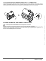
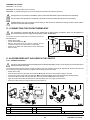
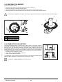
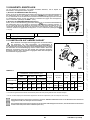
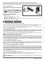
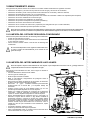
9. INSTALLAZIONE DELLA CALDAIA
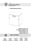
Dopo aver fissato la caldaia alla parete, sostituire il tappo inferiore
del sifone con quello presente nell'imballo riutilizzando la ghiera e
seguendo la procedura indicata in figura. Dopo aver riempito il sifone
controllare la sua tenuta. Si raccomanda di porre particolare cura nella fase di riempimento
dell’impianto di riscaldamento. In particolare aprire le valvole
termostatiche eventualmente presenti nell’impianto, far affluire
lentamente l’acqua al fine di evitare formazione di aria all’interno del circuito
primario finché non si raggiunge la pressione necessaria al funzionamento.
Infine eseguire lo sfiato degli eventuali elementi radianti all’interno
dell’impianto. BAXI non si assume alcuna responsabilità per danni derivati
dalla presenza di bolle d’aria all’interno dello scambiatore primario dovuta ad
errata o approssimativa osservanza di quanto sopra indicato. 3
2
1
Serrare con cautela gli attacchi idrici della caldaia (coppia massima 30
Nm).
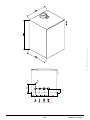
La figura della dima è disponibile alla fine del manuale nell'allegato
"SECTION" C. Determinata l’esatta ubicazione della caldaia fissare la dima alla parete.
Eseguire la posa in opera dell’impianto partendo dalla posizione degli attacchi
idrici e gas presenti nella traversa inferiore della dima stessa. Assicurarsi
che la parte posteriore della caldaia (schienale) sia il più possibile parallelo
al muro (in caso contrario spessorare la parte inferiore). E’ consigliabile
installare, nel circuito di riscaldamento, due rubinetti d’intercettazione
(mandata e ritorno) G1-1/2", che permettono, in caso d’interventi importanti,
di operare senza dover svuotare tutto l’impianto di riscaldamento. Per il 7221178.01
mercato italiano l’impianto deve essere dotato delle sicurezze previste dalla
Raccolta R (termostato sicurezza, pressostato sicurezza, valvola intercettazione combustibile, ecc..). Inserire a valle degli attacchi
idraulici della caldaia un separatore idraulico, dimensionato in funzione della portata massima della caldaia e dell’impianto. Nel
caso di impianti già esistenti e nel caso di sostituzioni è consigliabile, oltre a quanto citato, prevedere sul ritorno alla caldaia ed in
basso un vaso di decantazione destinato a raccogliere i depositi o scorie presenti anche dopo il lavaggio e che nel tempo possono
essere messi in circolazione. Fissata la caldaia alla parete effettuare il collegamento ai condotti di scarico e aspirazione, forniti
come accessori, come descritto nei successivi capitoli. Collegare il sifone ad un pozzetto di scarico assicurando una pendenza
continua. Sono da evitare tratti orizzontali. La caldaia è predisposta elettronicamente per il collegamento ad un bollitore sanitario
esterno.
Non
sollevare l'apparecchio facendo forza sulle parti in plastica come ad esempio il sifone e la torretta fumi.
9.1 POMPA DI CALDAIA
La pompa di caldaia (13 - "SECTION" A) è di tipo modulante e ha lo scopo di far circolare l'acqua tra la caldaia e il separatore
idraulico (per le prestazioni idrauliche vedere i grafici nell'allegato "SECTION" E). La circolazione dell'acqua nell'impianto è
demandata alle relative pompe (vedere paragrafo 11.2.3). Verificare che la portata dell'acqua di circolazione in caldaia non sia inferiore al valore riportato nella seguente tabella: Modello
Portata minima (l/h)
Portata di lavoro (l/h) con separatore idraulico BAXI
1.90
2000
4200
1.110
2250
4600
7221409.01 (1-03/15)
8
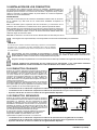
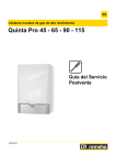
10.INSTALLAZIONE DEI CONDOTTI
L’installazione della caldaia può essere effettuata con facilità e flessibilità grazie agli
accessori forniti dei quali successivamente è riportata una descrizione. La caldaia è,
all’origine, predisposta per il collegamento ad un condotto di scarico - aspirazione di tipo
coassiale, verticale o orizzontale. La caldaia può essere utilizzata anche con condotti
separati utilizzando l'accessorio sdoppiatore.
AVVERTENZE
C13, C33 I terminali per lo scarico sdoppiato devono essere previsti all’interno di un
quadrato di 50 cm di lato. Istruzioni dettagliate sono presenti assieme ai singoli accessori.
C53 I terminali per l’aspirazione dell’aria comburente e per l’evacuazione dei prodotti
della combustione non devono essere previsti su muri opposti dell’edificio.
C63 La massima perdita di carico ΔP dei condotti non deve superare i valori riportati
nella tabella 1A. I condotti devono essere certificati per l’uso specifico e per una
temperatura superiore ai 100°C. Il terminale camino utilizzato deve essere certificato
secondo la Norma EN 1856-1.
C43, C83 Il camino o canna fumaria utilizzata deve essere idonea all’uso. Per
una migliore installazione si consiglia di utilizzare gli accessori forniti dal costruttore
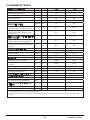
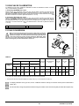
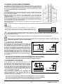
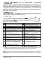
TABELLA 1A
∆P (Pa)
In caso d’installazione di condotti di scarico e di aspirazione non forniti da BAXI
S.p.A. è necessario che gli stessi siano certificati per il tipo di utilizzo ed abbiano una
perdita di carico massima in base ai valori riportati nella tabella a fianco.
1.90 MP
320
1.110 MP
370
Al fine di garantire una maggior sicurezza di funzionamento è necessario che i condotti di scarico fumi siano ben fissati al muro
mediante apposite staffe di fissaggio. Le staffe devono essere posizionate ad una distanza di circa 1 metro l'una dall'altra in
corrispondenza dei giunti.
La
pendenza minima verso la caldaia del condotto di scarico deve essere di 5 cm per metro di lunghezza.
ALCUNI ESEMPI D'INSTALLAZIONE DEI CONDOTTI DI SCARICO, E LE RELATIVE LUNGHEZZE AMMESSE, SONO
DISPONIBILI
ALLA FINE DEL MANUALE NELL' ALLEGATO "SECTION" D.
10.1CONDOTTI COASSIALI
Questo tipo di condotto permette lo scarico dei combusti e
l’aspirazione dell’aria comburente sia all’esterno dell’edificio,
sia in canne fumarie di tipo LAS. La curva coassiale a
90° permette di collegare la caldaia ai condotti di scaricoaspirazione in qualsiasi direzione grazie alla possibilità di
rotazione a 360°. Essa può essere utilizzata anche come
curva supplementare in abbinamento al condotto coassiale o
alla curva a 45°
In caso di scarico all’esterno il condotto scarico-aspirazione
deve fuoriuscire dalla parete per almeno 18 mm per permettere
il posizionamento del rosone in alluminio e la sua sigillatura
onde evitare le infiltrazioni d’acqua.
• L’inserimento di una curva a 90° riduce la lunghezza totale del condotto di 1 metro.
• L’inserimento di una curva a 45° riduce la lunghezza totale del condotto di 0,5 metri.
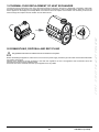
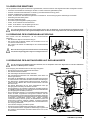
• La prima curva 90° non rientra nel calcolo della lunghezza massima disponibile. 10.2CONDOTTI SEPARATI
Questo tipo di condotto permette lo scarico dei combusti
sia all’esterno dell’edificio, sia in canne fumarie singole.
L’aspirazione dell’aria comburente può essere effettuata in
zone diverse rispetto a quelle dello scarico. L’accessorio
sdoppiatore, fornito come accessorio, è costituito da un
raccordo scarico Ø 110 mm (B) e da un raccordo aspirazione
aria Ø 110 mm (A). La guarnizione e le viti del raccordo
aspirazione aria da utilizzare sono quelle tolte in precedenza
dal tappo. La curva a 90° permette di collegare la caldaia ai condotti di
scarico e di aspirazione adattandolo alle diverse esigenze.
Essa può essere utilizzata anche come curva supplementare
in abbinamento al condotto o alla curva a 45°.
• L’inserimento di una curva a 90° riduce la lunghezza totale del condotto di 0,5 metri.
• L’inserimento di una curva a 45° riduce la lunghezza totale del condotto di 0,25 metri.
• La prima curva 90° non rientra nel calcolo della lunghezza massima disponibile. 9
7221409.01 (1-03/15)
S e z i o n e I N S TA L L AT O R E ( i t )
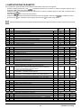
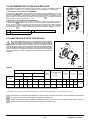
10.3CONDOTTI IN CASCATA
Questo tipo di condotti permette di evacuare i prodotti della combustione di più caldaie collegate in cascata attraverso un collettore
fumi comune. Il collettore deve essere utilizzato solamente per collegare le caldaie alla canna fumaria. I diametri disponibili sono:
Ø125 mm - Ø160 mm e Ø200 mm. Una gamma di accessori è disponibile a richiesta.
TABELLA 1B S e z i o n e I N S TA L L AT O R E ( i t )
MODELLO
CALDAIA
NUMERO MASSIMO DI CALDAIE
COLLEGABILI IN CASCATA
Ø160 mm
Ø200 mm
(250 kW Max)
(500 kW Max)
1.90
2
1.110
2
PARAMETRO P60
N°di giri/min (rpm) alla
Potenza minima
G20
G31
5
1450
1650
4
1500
1500
In questa tipologia di scarico, per ogni singola caldaia deve essere inserito il clapet fumi (valvola antiritorno) Ø 110/110 mm.
Modificare il parametro P60(a) come riportato nella tabbella 1B seguendo la procedura descritta al capitolo 14.
Il calcolo della canna fumaria deve
essere effettuato da un tecnico abilitato in fase di progetto dell'impianto secondo quanto
prescritto
dalle norme vigenti.
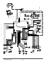
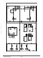
11.COLLEGAMENTI ELETTRICI
La sicurezza elettrica dell’apparecchio è raggiunta soltanto quando lo stesso è correttamente collegato ad un efficace impianto
di messa a terra, eseguito come previsto dalle vigenti Norme di sicurezza sugli impianti (DM n.37 del 22.01.08). La caldaia va
collegata elettricamente ad una rete di alimentazione 230 V monofase + terra mediante il cavo a tre fili in dotazione rispettando
la polarità Linea-Neutro.
L’allacciamento dev’essere effettuato tramite un interruttore bipolare con apertura dei contatti di almeno 3 mm.
In casi di sostituzione del cavo di alimentazione deve essere utilizzato un cavo armonizzato “HAR H05 VV-F” 3x0,75 mm2 con
diametro massimo di 8 mm. Per accedere alle morsettiere rimuovere il pannello frontale della caldaia (fiissato con due viti nella
parte inferiore), ruotare verso il basso la scatola comandi ed accedere alle morsettiere M1, M2, M3, destinate ai collegamenti
elettrici, togliendo il coperchio di protezione. I fusibili, del tipo rapido da 3,15 A, sono incorporati nella morsettiera di alimentazione
(estrarre il porta-fusibile di colore nero per il controllo e/o la sostituzione).
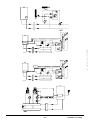
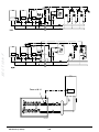
VEDERE LO SCHEMA ELETTRICO ALLA FINE DEL MANUALE NELL'ALLEGATO "SECTION" B
Verificare che l'assorbimento nominale complessivo degli accessori collegati all'apparecchio sia inferiore a 2A. Nel caso sia
superiore, è necessario interporre tra gli accessori e la scheda elettronica un relè.
I collegamenti presenti nelle morsettiere M1- M3 sono in alta tensione (230 V). Prima di procedere al collegamento assicurarsi
che l'apparecchio non sia alimentato elettricamente. Rispettare la polarità in alimentazione sulla morsettiera M1: L (LINEA) - N
(NEUTRO).
MORSETTIERA M1
(L) = Linea (marrone)
(N) = Neutro (celeste).
= Messa a Terra (giallo-verde).
(1) (2) = contatto per Termostato Ambiente.
Si rende necessario ripristinare il ponticello sui morsetti 12 della morsettiera M1 di caldaia nel caso in cui non venga
utilizzato il termostato ambiente oppure nel caso in cui non sia
collegato il Controlo Remoto fornito come accessorio.
MORSETTIERA M2
Morsetti 1 (retroilluminazione) - 2 (massa) - 3 (+12V): collegamento
Controllo Remoto (bassa tensione) fornito come accessorio.
Morsetti 4 - 5 (comune): collegamento Sonda Esterna (fornita come
accessorio)
Morsetti 6 - 5 (comune): 2° Sonda Ausiliaria (sonde impianto solare,
di cascata, a zone, etc).
Morsetti 7 - 5 (comune): 1° Sonda Ausiliaria (sonde impianto solare,
di cascata, a zone, etc).
Morsetti 9-10: collegamento della sonda del bollitore sanitario.
Morsetto 8: non utilizzato.
7221409.01 (1-03/15)
10
MORSETTIERA M3
Morsetto 1: non utilizzato
Morsetti 2 - 3: collegamento dispositivi di sicurezza esterni (INAIL)
Morsetti 4 - 5: collegamento pompa bollitore sanitario.
Morsetti 6 - 7: collegamento pompa riscaldamento impianto (esterna a valle del separatore idraulico). In caso l’apparecchio sia collegato ad un impianto a pavimento deve essere previsto, a cura dell’installatore, un termostato di
protezione
per la salvaguardia dell'impianto dalle sovratemperature.
Per il passaggio dei cavetti di collegamento delle morsettiere, utilizzare gli appositi fori "passa-fissa cavi" presenti sul fondo
della
caldaia.
Per il collegamento delle pompe esterne è necessario interporre un relè 250Vac/250Vac con corrente nominale di almeno
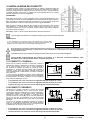
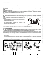
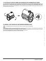
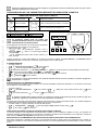
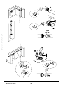
16A e che supporti correnti di spunto superiori a 100A. 11.1COLLEGAMENTO TERMOSTATO AMBIENTE
Per collegare il Termostato Ambiente alla caldaia, agire come
di seguito descritto:
Min. 200 mm
• togliere l'alimentazione elettrica alla caldaia;
• accedere alla morsettiera M1;
• rimuovere il ponticello ai capi dei contatti 1-2 e collegare i
cavetti del Termostato Ambiente;
• alimentare elettricamente la caldaia ed assicurarsi che il
Termostato Ambiente funzioni correttamente.
1500mm
11.2ACCESSORI NON INCLUSI NELLA DOTAZIONE
11.2.1 CONTROLLO REMOTO
Il cavetto (1) proveniente dalla morsettiera M2 di caldaia è l'alimentazione elettrica (12 V) per la retroilluminazione del display. Il
collegamento di questo cavetto non è necessario per il funzionamento del Controllo Remoto.
Per il funzionamento della caldaia, con Controllo Remoto installato a parete, è necessario l'acquisto dell'accessorio A fornito
con la base A1. Vedere anche le istruzioni fornite con il kit dell'accessorio A per le corrette operazioni di montaggio ed utilizzo.
La procedura da seguire è la seguente:
• Togliere l'alimentazione elettrica alla caldaia.
• Far passare i tre cavetti, provenienti dalla morsettiera M2 di caldaia, nel foro della base A1 da applicare al muro.
• Collegare i cavetti 1-2-3 della morsettiera di caldaia M2 rispettivamente ai morsetti (1)-(2)-(3) della morsettiera della base A1.
• Fissare la base A1 al muro mediante i tasselli e le viti forniti in dotazione all'accessorio.
• Applicare il Pannello di Controllo A sulla base fissata a muro avendo cura di non esercitare una forza eccessiva.
• Alimentare elettricamente la caldaia assicurandosi che il Controllo Remoto si accenda.
A
A - A1
A1
B
A1
B1
A
B1
B
Pannello di Controllo
A1
Base per Pannello di Controllo a parete
B
Accessorio interfaccia a led
B1
Base per Accessorio interfaccia a led
(1)
Retroilluminazione del display +12V
(2)
Collegamento di massa
A
11
A
A1
(3)
Alimentazione/Segnale +12V
7221409.01 (1-03/15)
S e z i o n e I N S TA L L AT O R E ( i t )
I collegamenti presenti nella morsettiera M1 sono in alta tensione (230 V). Prima di procedere al collegamento assicurarsi che
l'apparecchio non sia alimentato elettricamente. Rispettare la polarità in alimentazione L (LINEA) - N (NEUTRO).
Utilizzando il Controllo Remoto è possibile impostare la programmazione oraria in riscaldamento e in sanitario. Allo scopo
vedere
le informazioni fornite con l'accessorio stesso.
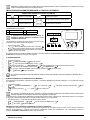
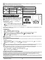
IMPOSTAZIONE PARAMETRI MEDIANTE IL CONTROLLO REMOTO
SIMBOLOGIA RIFERITA AL CONTROLLO REMOTO
Ruotare la manopola B
Visualizzazione display
Premere la manopola B
Premere insieme il tasto A e la manopola B
Premere il tasto A o C
Premere insieme i tasti A e C
S e z i o n e I N S TA L L AT O R E ( i t )
LEGENDA MENU DI FIGURA
1
2
Utente finale
Messa in servizio
3
4
Specialista
OEM
SI CONSIGLIA DI ANNOTARE, NELLA TABELLA AL
TERMINE DI QUESTO MANUALE ISTRUZIONI, TUTTI I
PARAMETRI MODIFICATI.
La procedura per accedere ai quattro menu che consentono la
programmazione della caldaia è la seguente:
• dal menu principale C.
A e C (mantenere premuti circa 6 secondi) •
B
menu 1-2-3-4 (vedere la figura a lato e la legenda).
C ripetutamente per ritornare indietro di un menu alla
• volta fino al menu principale.
Quando il Pannello di Controllo è installato a parete è necessario abilitare la sonda ambiente e la modulazione della temperatura
di mandata, la procedura da seguire è la seguente:
A) SONDA AMBIENTE
• Accedere al menu 2.
B Unità di comando B per confermare.
•
B riga di programma 40 (Impiego come) B.
•
B (in senso antiorario) Unità ambiente 1 B per confermare (la sonda ambiente adesso è attiva).
•
C per ritornare al menu precedente quindi B Configurazione B.
•
B
la riga di programma 5977 (Funzione input H5) quindi
B per confermare.
•
B
Nessuno
B per confermare.
•
Per il corretto funzionamento dell'unità ambiente durante la fascia oraria ridotta è necessario impostare il parametro 5977 = "
nessuno".
B) MODULAZIONE DELLA TEMPERATURA DI MANDATA
Per impostare la temperature di mandata modulante, è necessario disabilitare il parametro 742 (HC1). La procedura da seguire
è la seguente:
• Accedere al menu 2.
B Circuito riscaldamento 1 •
confermare. "---" quindi • B (in senso antiorario) B per confermare B 742 (Setp mandata termost.amb)
B per
B per confermare.
Se, ruotando la manopola B dal menu principale, il display visualizza la temperatura di mandata caldaia anzichè quella
ambiente,
significa che il parametro 742 non è stato impostato correttamente.
Al termine di ogni configurazione dell'impianto (esempio abbinamento solare, collegamento unità bollitore esterno, ecc) eseguire
la seguente procedura per aggiornare la scheda di caldaia alla nuova configurazione:
• Accedere al menu 2 come descritto all'inizio di questo capitolo.
B Configurazione B B riga di programma 6200 quindi •
B Sì quindi
B per confermare.
•
B.
IMPIANTO A ZONE CON INSTALLAZIONE DEL CONTROLLO REMOTO
Il collegamento elettrico e le regolazioni necessarie per la gestione di un impianto diviso in zone, in cui è previsto il Controllo
Remoto, risulta differente a seconda degli accessori collegati alla caldaia. Per l'installazione e la configurazione, vedere le
istruzioni del Modulo di Espansione fornito come accessorio.
7221409.01 (1-03/15)
12
REGOLAZIONE TEMPERATURA SU IMPIANTO DI RISCALDAMENTO IN ALTA TEMPERATURA
Allo scopo di evitare frequenti accensioni e spegnimenti, si raccomanda di alzare il setpoint minimo di temperatura della caldaia
in riscaldamento modificando, con la stessa procedura descritta al punto B, il paramentro 740 ad un valore non inferiore a 45°C.
REGOLAZIONE TEMPERATURA SU IMPIANTO DI RISCALDAMENTO A BASSA TEMPERATURA
Per un impianto a bassa temperatura (come ad esempio un impianto a pavimento), si raccomanda di abbassare il setpoint
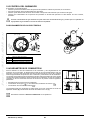
massimo di temperatura della caldaia in riscaldamento impostando il parametro 741 (punto B) ad un valore non superiore a 45°C. 11.2.2 SONDA ESTERNA
Per il collegamento di tale accessorio, vedere la figura a lato
(morsetti 4-5) oltre alle istruzioni fornite con la sonda stessa.
Con Sonda Esterna collegata i tasti , presenti sul
pannello comandi di caldaia, svolgono la funzione di traslazione
parallela della curva climatica Kt impostata (vedi l'allegato
"SECTION" E e parametro P03 sulla tabella al capitolo 14).
Per aumentare la temperatura ambiente del locale premere il
tasto +, per diminuirla premere il tasto -.
• Accedere al menu come descritto al capitolo 14.
• Selezionare il paramentro P03.
• Selezionare la curva climatica scegliendola tra quelle disponibili, vedere il grafico delle curve alla fine del manuale nell'allegato
"SECTION" E (la curva preimpostata è la 1,5).
LEGENDA GRAFICO CURVE Kt - "SECTION" E Temperatura di mandata
Temperatura esterna
11.2.3 POMPA IMPIANTO DI RISCALDAMENTO
La pompa dell'impianto deve essere installata a valle del separatore idraulico. La scelta dello stesso deve essere effettuata in
base alle caratteristiche di portata/prevalenza richieste dall'impianto (vedere l'allegato "SECTION" F).
Per il collegamento delle pompe esterne è necessario interporre un relè 250Vac/250Vac con corrente nominale di almeno
16A e che supporti correnti di spunto superiori a 100A.
11.2.4 BOLLITORE ESTERNO
La caldaia è predisposta elettricamente per la connessione di un bollitore esterno. La connessione idraulica del bollitore esterno
è schematizzata nella figura nell'allegato "SECTION" F. La pompa del bollitore deve essere collegata ai morsetti 4-5 della
morsettiera M3 (vedere l'allegato "SECTION" B). Il bollitore va installato a valle del separatore idraulico. Utilizzare la sonda fornita
come accessorio e collegarla ai morsetti 9-10 della morsettiera M2 (vedere l'allegato "SECTION" B). Verificare che la potenza di
scambio della serpentina del bollitore sia corretta per la potenza della caldaia.
Per il collegamento delle pompe esterne è necessario interporre un relè 250Vac/250Vac con corrente nominale di almeno
16A e che supporti correnti di spunto superiori a 100A.
MODULI ESTERNI DI GESTIONE IMPIANTO
La caldaia può gestire in maniera indipendente fino a tre circuiti di riscaldamento tramite l'utilizzo di accessori esterni quali unità
ambiente, controlli remoti e moduli esterni (AGU 2.550 e AVS 75). L'elettronica che equipaggia questa caldaia comprende, inoltre,
un'ampia gamma di funzioni per la personalizzazione e la gestione di diverse tipologie di impianto. Per il corretto funzionamento
del sistema, è indispensabile assegnare ad ogni accessorio utilizzato un numero (da 1 a 3) che permetta alla scheda di caldaia di
riconoscerlo. A tale scopo si raccomanda di leggere con particolare attenzione anche le istruzioni fornite a corredo degli accessori
stessi.
11.2.5 ZONE MISCELATE ("SECTION" F)
Utilizzando il modulo esterno AVS75, fornito come accessorio, è possibile gestire una zona miscelata. Tale accessorio è in grado
di gestire: una pompa di zona, una valvola miscelatrice, una sonda di temperatura, un termostato di sicurezza e un termostato
ambiente. Per la connessione dei componenti e la regolazione del sistema, leggere quanto riportato nel manuale fornito con
l'accessorio.
11.2.6 CALDAIE IN CASCATA ("SECTION" F)
Tramite l’utilizzo del modulo esterno AVS75, fornito come accessorio, è possibile gestire un impianto di riscaldamento con un
massimo di 16 caldaie collegate in cascata ed un eventuale accumulo separato, per la fornitura di acqua calda sanitaria. Tale
accessorio, collegato a una delle caldaie di cascata, è in grado di controllare direttamente i componenti del circuito fino ad un
massimo di 3 uscite relè indipendenti, 2 sonde di temperatura, 1 connettore per termostato limite in alta tensione e 1 ingresso di
comando (es. termostato ambiente). Per il funzionamento dell’impianto è inoltre necessaria l’installazione di una unità interfaccia
OCI 345 su ogni caldaia che compone la cascata. Per la regolazione dei parametri di caldaia vedere il capitolo “IMPOSTAZIONE
PARAMETRI”. Per la connessione dei componenti e la regolazione del sistema, leggere quanto riportato nel manuale fornito con
l'accessorio.
11.2.7 IMPIANTO SOLARE ("SECTION" F)
Tramite l’utilizzo del modulo esterno AGU 2.550, fornito come accessorio, è possibile gestire un impianto solare. Per il collegamento
dell'impianto vedere le istruzioni fornite con l'accessorio stesso. GLI
SCHEMI IDRAULICI DEI CASI DESCRITTI SONO RIPORTATI ALLA FINE DEL MANUALE NELL'ALLEGATO "SECTION" F
13
7221409.01 (1-03/15)
S e z i o n e I N S TA L L AT O R E ( i t )
IMPOSTAZIONE DELLA CURVA CLIMATICA "Kt"
Per impostare la curva climatica kt desiderata, procedere nel
modo seguente:
11.3COLLEGAMENTO SICUREZZE INAIL
I dispositivi di sicurezza previsti dalla Raccolta R (termostato e pressostato di sicurezza circuito di
riscaldamento), devono essere collegati elettricamente (in serie) ai morsetti 2-3 della morsettiera
M3. In caso di intervento di questi dispositivi la caldaia si arresta segnalando il codice di anomalia
E110.
S e z i o n e I N S TA L L AT O R E ( i t )
12.PRIMA ACCENSIONE - FUNZIONI SPECIALI
Dopo aver alimentato elettricamente la caldaia, sul display appare il codice "311" e l'apparecchio è pronto per la procedura di
"prima accensione".
Seguire la procedura “FUNZIONE DEGASAMENTO IMPIANTO” indicata al paragrafo seguente e attivare il programma 312.
Dopo aver completato questa operazione, l’apparecchio è pronto per l’accensione del bruciatore.
Durante
questa fase si raccomanda di mantenere la pressione dell’impianto a un valore compreso tra 1 e 1,5 bar.
12.1FUNZIONE DEGASAMENTO IMPIANTO
Questa funzione consente di agevolare l'eliminazione dell'aria all'interno del circuito di riscaldamento quando viene installata la
caldaia in utenza oppure a seguito di manutenzione con svuotamento dell'acqua del circuito primario.
Per attivare la funzione di degasamento impianto premere contemporaneamente i tasti
per 6 secondi. Quando la funzione
è attiva compare sul display la scritta On per alcuni secondi, seguirà la riga di programma 312.
La scheda elettronica attiverà un ciclo di accensione/spegnimento della pompa della durata di 10 minuti. La funzione si fermerà
automaticamente alla fine del ciclo. Per uscire manualmente da questa funzione, premere un’altra volta contemporaneamente i
tasti sopracitati per 6 secondi.
12.2FUNZIONE TARATURA
Per agevolare la taratura della valvola del gas procedere nel modo seguente:
• Premere contemporaneamente i tasti e per almeno 6 secondi. Quando la funzione è attivata il display visualizza per
qualche secondo la scritta “On” in seguito appare la riga di programma “304” alternata al valore % di potenza della caldaia.
per effettuare una regolazione graduale della potenza (sensibilità 1%).
• Agire sui tasti • Per uscire premere contemporaneamente per almeno 6 secondi i tasti come descritto nel primo punto.
Premendo
il tasto è possibile visualizzare, per 15 secondi, il valore istantaneo della temperature di mandata.
12.3FUNZIONE SPAZZACAMINO
Attivata questa funzione, la caldaia si porta alla massima potenza in riscaldamento. Per attivare la funzione agire come di seguito
descritto:
• premere contemporaneamente i tasti per 6 secondi, sul display è visualizzata la scritta "303" in alternanza al valore di
potenza della caldaia.
e per regolare la potenza della caldaia 1=minimo, 2=massimo sanitario, 3=massimo riscaldamento.
• Agire sui tasti • Per interrompere la funzione ripetere l'azione descritta nel primo punto.
13.ANOMALIE NON RESETTABILI DALL'UTENTE
In caso di ANOMALIE non resettabili mediante il tasto
(quali per esempio E151 o il
superamento dei 5 tentativi di RESET manuale da parte dell'utente) è necessario procedere
al RESET della scheda premendo il tastino nero ( R) posizionato sotto al cappuccio in gomma
(simbolo
) del pannello comandi frontale (figura a lato).
7221409.01 (1-03/15)
14
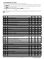
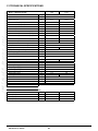
14.IMPOSTAZIONE PARAMETRI
Per programmare i parametri della scheda elettronica della caldaia, agire nel modo seguente:
• Premere contemporaneamente i tasti e mantenerli premuti per 6 secondi fino a quando sul display appare la riga di
programma “P02” alternata al valore impostato (°C);
e mantenerlo premuto per 6 secondi fino a quando sul display appare la scritta "On", rilasciare il tasto e
• Premere il tasto sul display appare "P01";
per scorrere la lista di parametri;
• Agire sui tasti , il valore del parametro selezionato inizia a lampeggiare, agire sui tasti
per modificare il valore;
• Premere il tasto per confermare il valore oppure premere il tasto per uscire senza salvare.
• premere il tasto Ulteriori
informazioni in merito ai parametri elencati nella tabella che segue sono fornite a corredo con gli accessori richiesti.
(b)
P01
P02
P03
P04
P05
P06
P07
P08
P09
P10
700
712
720
721
726
740
741
742
750
834
P11
P12
P13
P14
P15
P16
P17
P18
1000
1010
1012
1020
1021
1026
1040
1041
P19
1042
P20
P21
1050
1134
* Modo di funzionamento (0=Antigelo, 1=Automatico, 3=T.comfort )
* Temperatura ambiente ridotta
* Pendenza curva “Kt”
* Slittamento curva “Kt”
* Adattamento curva “Kt” (0=off)
Setpoint temperatura di mandata (valore minimo)
Setpoint temperatura di mandata (valore massimo)
* Abilitazione della temperatura modulante se impostato = “---”
* Influenza ambiente (“---” = disabilitato)
* Rapidità apertura/chiusura valvola mix
PARAMETRI RISCALDAMENTO ZONA2 (con Modulo di Espansione accessorio)
* Modo di funzionamento (0=Antigelo, 1=Automatico, 3=T.comfort )
* Temperatura ambiente di Comfort
* Temperatura ambiente ridotta
* Pendenza curva “Kt”
* Slittamento curva “Kt”
* Adattamento curva “Kt” (0=off)
Setpoint temperatura di mandata (valore minimo)
Setpoint temperatura di mandata (valore massimo)
* Abilitazione della temperatura modulante se impostato = “---” (setpoint
temperatura di mandata se P63=0)
* Influenza ambiente (“---” = disabilitato )
* Rapidità apertura/chiusura valvola mix
PARAMETRI SANITARIO
P22
1620
P23
1640
P24
1641
P25
P26
1663
5470
P27
P28
P29
P30
P31
P32
P33
2243
2217
2250
2441
2455
2720
2721
P34
P35
P36
P37
P38
P39
3810
3811
3830
3850
5050
5051
°C
°C
°C
°C
%
S
Valore di
Fabbrica
3
16
1,5
0
1
25
80
80
50
30
PARAMETRI RISCALDAMENTO ZONA1 (zona principale)
Modo di funzionamento in sanitario (con Controllo Remoto)
0=sempre attivo, 1=segue la programmazione oraria del riscaldamento,
2=segue la programmazione oraria del sanitario.
Funzione anti-legionella Disabilitata
0=disabilitata , 1=periodica (in funzione di P24)
Attivazione funzione anti-legionella periodica (solo se P23 =1)
1=giornaliero , 2..6=a intervalli di 2..6 giorni , 7=una volta a settimana
Setpoint temperatura di ricircolo (pompa sanitaria supplementare)
Durata tempo di preriscaldo per circuito sanitario (1=10’ -- 144=1440’)
PARAMETRI CALDAIA
Tempo minimo di spegnimento del bruciatore
Setpoint antigelo
Tempo di post-circolazione pompa
Velocità max ventilatore (riscaldamento)
Differenziale minimo di spegnimento della caldaia
Non utilizzato (NON modificare questo parametro)
Non utilizzato (NON modificare questo parametro)
Minimo
Massimo
0
4
0,1
- 4,5
0
8
25
25
1
30
3
35
4
4,5
1
80
80
80
100
873
°C
°C
°C
°C
°C
3
20
16
1,5
0
1
25
80
0
4
4
0,1
- 4,5
0
8
25
3
35
35
4
4,5
1
80
80
°C
80
25
80
%
s
50
30
1
30
100
873
-
2
0
2
-
0
0
1
-
7
1
7
°C
min
45
0
8
0
80
144
min
°C
min
rpm
°C
-
3
5
3
xxx
5
0
1
0
-20
0
0
0
0
1
20
20
240
8000
20
1
2
PARAMETRI CIRCUITO SOLARE (con Modulo di Espansione accessorio)
Differenziale di temperatura - accensione
Differenziale di temperatura - spegnimento
Funzione avvio pompa solare (“---” = disabilitata)
Protezione sovra-temperatura collettore pannelli solari (“---“ = disabilitato)
Temperatura max di carica bollitore sanitario
Temperatura massima bollitore
°C
°C
min
°C
°C
°C
8
4
----65
90
0
0
5
30
8
8
40
40
60
350
95
95
15
7221409.01 (1-03/15)
S e z i o n e I N S TA L L AT O R E ( i t )
(a)
S e z i o n e I N S TA L L AT O R E ( i t )
CONFIGURAZIONE
P40
P41
P42
5700
5710
5715
Non utilizzato (NON modificare questo parametro)
Circuito di riscaldamento della zona 1 (1=abilitato)
Circuito di riscaldamento della zona 2 (1= abilitato )
P43
5730
Sonda sanitario (1=sonda bollitore, 2=termostato, 3=sonda istantanea)
P44
P45
P46
P47
P48
P49
P50
5890
5931
5932
5977
6020
6024
6046
Non utilizzato (NON modificare questo parametro)
* Ingresso sonda BX2 (prima sonda ausiliaria - capitolo 11)
* Ingresso sonda BX3 (seconda sonda ausiliaria - capitolo 11)
* Ingresso H5 (ingresso multifunzionale - 18=Termostato Ambiente)
* Configurazione Modulo di Espansione accessorio
Ingresso EX21 modulo 1 (configurazione termostato di sicurezza HC)
Ingresso H2 modulo 1 (Ingresso multifunzione)
P51
P52
P53
P54
P55
P56
6097
6110
6220
6600
6601
6640
P57
P58
7045
6704
Tipo di sensore del collettore (1= NTC, 2= Pt 1000)
Costante di tempo dell’edificio (dipende dal grado di isolamento dell’edificio)
Versione Software
Indirizzo dispositivo LPB (collegamento via BUS)
Indirizzo segmento LPB (collegamento via BUS)
Sorgente orologio
-
--1
0
--0
0
--1
1
1
1
3
-
33
0
0
18
0
0
0
0
0
0
0
0
0
0
43
19
19
32
7
1
58
ore
-
2
15
--1
0
0
1
0
0
1
0
0
2
50
99
16
14
3
mesi
-
xxx
1
0
0
240
1
rpm
rpm
rpm
xxx
xxx
xxx
0
0
0
8000
8000
8000
MANUTENZIONE
Tempo trascorso dopo la manutenzione
Visualizzare/Nascondere il codice interno di anomalia secondario (0=no)
CONTROLLO BRUCIATORE
P59
P60
P61
9512
9524
9529
P62
P63
P64
-
Velocità di accensione richiesta
Richiesta minima velocità di funzionamento (bassa velocità)
Richiesta massima velocità di funzionamento (alta velocità)
PARAMETRI PANNELLO COMANDI DI CALDAIA
Unità di misura (1=bar, °C – 2=PSI, °F)
Funzionamento pannello comandi : (1=centrale, 0=locale)
Versione Software
-
1
1
xx
1
0
0
2
1
999
* vedere il capitolo “Accessori non inclusi nella dotazione”
xx: il valore dipende dalla versione del software
xxx : il valore dipende dal tipo di caldaia
(a): parametri letti sul pannello frontale della caldaia (pannello comandi fisso)
(b): parametri letti sul Controllo Remoto
7221409.01 (1-03/15)
16
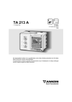
15.TARATURA VALVOLA GAS
Per eseguire la taratura della valvola del gas attivare la funzione taratura come descritto al
capitolo 12.2 ed eseguire le operazioni di seguito riportate:
1) Taratura della portata termica MASSIMA
Verificare che la misurata sul condotto di scarico, con caldaia funzionante alla massima
portata termica, sia quella riportata nella tabella 2 (tolleranza ammessa +/- 0,5%). In caso
contrario agire sulla vite di regolazione (V) presente sulla valvola gas. Ruotare la vite in
senso orario per diminuire il tenore di ed in senso antiorario per aumentarlo (tolleranza
ammessa +/- 0,2%).
2) Taratura della portata termica RIDOTTA
Verificare che la misurata sul condotto di scarico, con caldaia funzionante alla minima
portata termica, sia quella riportata nella tabella 2 (tolleranza ammessa +/- 0,5%). In caso
contrario, rimuovere il tappo filettato in ottone presente sulla valvola gas e agire sulla vite di
regolazione (K). Ruotare la vite in senso orario per aumentare il tenore di ed in senso
antiorario per diminuirlo (tolleranza ammessa +/- 0,2%).
Vite regolazione portata gas
Segnale pressione camera stagna
K
Pi
Vite regolazione OFFSET
Presa pressione alimentazione gas
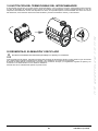
15.1CAMBIO GAS
In caso di trasformazione per il funzionamento da gas metano a gas
propano (GPL), prima di effettuare la taratura della valvola gas, come
sopra descritto, effettuare la sostituzione del'assieme venturi ( B)
come indicato in figura. Per la sostituzione è necessario smontare il tubo di
connessione gas (dado filettato G1") e rimuovere le tre viti di fissaggio della
flangia. Al termine dell'operazione di sostituzione, verificare che non ci siano
perdite di gas. Modificare i parametri (numero di giri del ventilatore) come
riportato nella tabella 2 seguendo la procedura descritta al capitolo 14.
TABELLA 2
PARAMETRI - N°di giri/min (rpm)
Modello
caldaia
P60**
P30 – P61 **
P59**
Potenza min
Potenza max
Potenza accensione
VENTURI
Ø (mm)
UGELLI GAS
Ø (mm)
G20
CO2 Min
(%)
CO2 Max
(%)
G20
G31
G20
G31
G20
G31
G20-G31
1.90
1250
1500
6500
6200
2400
2400
34
5,6(n°2) 4,5(n°2)
*8,5 *9,9 *9,0 *10
1.110
1300
1300
6900
6700
2500
3000
38
6,4(n°2) 5,0(n°2)
*9,0
G31
CO Max
(ppm)
G20 G31 G20 G31 G20/G31
*9,5 *9,2
< 250
*10
* valore CO2 con mantello chiuso. Senza mantello (camera aperta) il valore letto è inferiore di 0,2%.
** valore letto sul display del pannello frontale della caldaia da moltiplicare x 10 (es. 150 corrisponde a 1500 giri/min).
Per facilitare le operazioni di taratura della valvola gas è possibile impostare la “funzione taratura” direttamente sul pannello
comandi della caldaia come descritto al capitolo 12.2.
Per i condotti in cascata, modificare il parametro P60 aumentando di 200 il numero di giri del ventilatore (vedere la tabella
1B al capitolo 10.3).
17
7221409.01 (1-03/15)
S e z i o n e I N S TA L L AT O R E ( i t )
V
PI
16.DISPOSITIVI DI REGOLAZIONE E SICUREZZA
La caldaia è costruita per soddisfare tutte le prescrizioni delle Normative europee di riferimento, in particolare è dotata di: • Termostato di sicurezza
Questo dispositivo, il cui sensore è posizionato sulla mandata del riscaldamento, interrompe l’afflusso del gas al bruciatore in
caso di surriscaldamento dell’acqua contenuta nel circuito primario. In queste condizioni la caldaia va in blocco e solo dopo aver
rimosso la causa dell’intervento è possibile ripetere l’accensione premendo il tasto .
• Termostato flangia scambiatore (260°C)
Questo dispositivo è posizionato sulla flangia dello scambiatore e interrompe l’afflusso del gas al bruciatore in caso di
surriscaldamento dello scambiatore dovuto al cedimento dell'isolamento anteriore o alla non corretta tenuta delle guarnizioni
della flangia. Premere il pulsante di ripristino, posizionato sul termostato stesso, dopo aver appurato le cause d’intervento, quindi
premere il pulsante di reset presente sul pannello comandi della caldaia.
S e z i o n e I N S TA L L AT O R E ( i t )
• Termofusibile
Questo dispositivo è posizionato sulla parte posteriore dello scambiatore e interrompe l’afflusso del gas al bruciatore in caso
di surriscaldamento dello scambiatore dovuto al cedimento dell'isolamento posteriore. In caso d'intervento di questo dispositivo
è necessario smontare lo scambiatore e sostituire il termofusibile (vedere paragrafo “SOSTITUZIONE DEL TERMOFUSIBILE
DELLO SCAMBIATORE”).
E’ vietato mettere fuori servizio questo dispositivo di sicurezza. • Sonda NTC fumi Questo dispositivo è posizionato sul condotto fumi. La scheda elettronica blocca l’afflusso di gas al bruciatore in caso di
sovratemperatura. É necessario premere il tasto per ristabilire le normali condizioni di funzionamento. L’operazione di ripristino, di cui sopra, è possibile solo se la temperatura è < 90°C. E’ vietato mettere fuori servizio questo dispositivo di sicurezza • Rilevatore a ionizzazione di fiamma L'elettrodo di rilevazione garantisce la sicurezza in caso di mancanza gas o interaccensione incompleta del bruciatore principale.
per ristabilire le normali condizioni di funzionamento.
In queste condizioni la caldaia va in blocco. É necessario premere il tasto • Pressostato idraulico Questo dispositivo permette l’accensione del bruciatore principale solamente se la pressione dell’impianto è superiore a 0,5 bar.
• Postcircolazione pompa La postcircolazione della pompa, ottenuta elettronicamente, ha una durata di 3 minuti e viene attivata, nella funzione riscaldamento,
dopo lo spegnimento del bruciatore principale per l’intervento del termostato ambiente.
• Dispositivo antigelo La gestione elettronica della caldaia è provvista di una funzione “antigelo” in riscaldamento ed in sanitario che con temperatura
di mandata impianto inferiore ai 5 °C fa funzionare il bruciatore fino al raggiungimento in mandata di un valore pari a 30 °C. Tale
funzione è operativa se la caldaia è alimentata elettricamente, se c’è gas e se la pressione dell’impianto è quella prescritta.
• Antibloccaggio pompe In caso di mancanza di richiesta di calore, in riscaldamento e/o in sanitario, per un tempo di 24 ore consecutive le pompe si
mettono in funzione automaticamente per 10 secondi.
• Valvola di sicurezza idraulica (circuito di riscaldamento) Questo dispositivo, tarato a 4 bar, è a servizio del circuito di riscaldamento. Si consiglia di raccordare la valvola di sicurezza ad
uno scarico sifonato. E’ vietato utilizzarla come mezzo di svuotamento del circuito di riscaldamento.
• Pre-circolazione della pompa di caldaia In caso di richiesta di funzionamento in riscaldamento, l’apparecchio può effettuare una precircolazione della pompa prima di
effettuare l’accensione del bruciatore. La durata di tale precircolazione dipende dalla temperatura di funzionamento e dalle
condizioni d’installazione e varia da pochi secondi ad alcuni minuti.
Le funzioni relative ai dispositivi di regolazione e sicurezza sono operative se la caldaia è alimentata elettricamente.
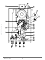
17.CARATTERISTICHE PORTATA/PREVALENZA ALLA PLACCA
La pompa utilizzata è del tipo modulante e svolge la funzione di far circolare l'acqua tra la caldaia ed il separatore idraulico. LEGENDA GRAFICI POMPA - "SECTION" E Q
H
PORTATA
PREVALENZA
I GRAFICI DELLA PORTATA/ PREVALENZA ALLA PLACCA DELLA POMPA SONO DISPONIBILI ALLA FINE DEL MANUALE
NELL'ALLEGATO "SECTION" E.
7221409.01 (1-03/15)
18
18.MANUTENZIONE ANNUALE
Allo scopo di assicurare un’efficienza ottimale della caldaia è necessario effettuare annualmente i seguenti controlli:
•
•
•
•
Prima di iniziare qualsiasi intervento di manutenzione, assicurarsi che la caldaia sia scollegata dall’alimentazione. Dopo
l’intervento,
resettare i parametri di funzionamento originali della caldaia se modificati.
18.1PULIZIA DEL SIFONE DI SCARICO CONDENSA
Svitare la parte inferiore del sifone "A" di scarico della condensa.
• Pulire il fondo del sifone con acqua.
• Riempire d’acqua la sezione inferiore fino a raggiungere una
distanza di 10 mm dal bordo superiore.
• Riposizionare la sezione inferiore contro il sifone di scarico della
condensa. Se il dispositivo viene azionato con il pozzetto di condensa
vuoto, si corre il rischio di avvelenamento a causa dell’emissione
di
gas di scarico.
A
CR_0510
18.2PULIZIA DELLO SCAMBIATORE LATO FUMI
Prima di iniziare a pulire lo scambiatore di calore aspettare che la temperatura sia inferiore a 40°C e proteggere tutti i componenti
elettrici dagli spruzzi d'acqua.
Per pulire lo scambiatore di calore, procedere come di seguito
descritto:
• Togliere l’alimentazione elettrica alla caldaia.
• Chiudere il rubinetto di ingresso gas.
• Rimuovere il coperchio frontale dalla caldaia.
• Abbassare la scatola elettrica, assicurandosi di proteggerla dal
contatto con l’acqua.
• Scollegare i cavi dell’elettrodo di accensione, di rilevazione di
fiamma e del termostato flangia scambiatore.
• Rimuovere il gruppo ventilatore-mixer-bruciatore-flangia svitando i
6 dadi M6 e il raccordo sotto al mixer.
• Proteggere dall'acqua il pannello isolante posteriore (2) con una
pellicola impermeabile disponibile nel kit di pulizia.
• Aspirare accuratamente i residui all'interno della camera di
combustione e rimuovere eventuali incrostazioni utilizzando una
spazzola con setole in plastica disponibile nel kit di pulizia.
• Irrorare abbondantemente le superfici da detergere (1) utilizzando
l'appropriato liquido BX-HT Cleaner o similare mediante apposito
spruzzatore e attendere 10 minuti (possono essere utilizzati
altri prodotti previa consultazione del servizio di assistenza
tecnica autorizzata). Spazzolare senza sciacquare e ripetere
l'applicazione di BX-HT Cleaner. Trascorsi ulteriori 10 minuti
spazzolare nuovamente. Nel caso di risultato non soddisfacente
ripetere l'operazione.
• Al termine della pulizia risciacquare con acqua.
• Sostituire la guarnizione della flangia supporto bruciatore.
• Per il riassemblaggio procedere in senso inverso avvitando i 6 dadi
della flangia con una coppia di 5,5 Nm.
19
2
1
7221409.01 (1-03/15)
S e z i o n e I N S TA L L AT O R E ( i t )
•
•
•
•
•
•
Verifica dell’aspetto e della tenuta delle guarnizioni del circuito gas e del circuito di combustione;
Verifica dello stato e della corretta posizione degli elettrodi di accensione e rilevazione di fiamma;
Verifica dello stato del bruciatore ed il suo corretto fissaggio;
Verifica delle eventuali impurità presenti all’interno della camera di combustione. Utilizzare allo scopo un aspirapolvere per la
pulizia;
Verifica della corretta taratura della valvola gas;
Verifica della pressione dell’impianto di riscaldamento;
Verifica della pressione del vaso espansione (impianto);
Verifica che il ventilatore funzioni correttamente;
Verifica che i condotti di scarico e aspirazione non siano ostruiti;
Verifica delle eventuali impurità presenti all’interno del sifone. 18.3CONTROLLO DEL BRUCIATORE
Il bruciatore non ha bisogno di pulizia.
• Verificare la presenza di danni sulla superficie del bruciatore. Sostituire il bruciatore se necessario.
• Controllare il posizionamento della sonda di rilevazione di fiamma.
• Verificare che la distanza dell’elettrodo di accensione rientri nella tolleranza mostrata in figura.
• Verificare che l’isolamento della superficie del bruciatore nella flangia del bruciatore non sia danneggiato. In caso contrario,
provvedere alla sostituzione.
Collegare l’alimentazione gas usando una guarnizione nuova. Aprire l’alimentazione gas e verificare che il bruciatore non
presenti perdite di gas usando uno spray per il rilevamento di perdite.
POSIZIONAMENTO
ELETTRODI
d
b
7,5 ±1 (1.90)
5,0 ±1 (1.110)
a
0)
(1.9 10)
±1
.1
10 ±1 (1
7,5
S e z i o n e I N S TA L L AT O R E ( i t )
c
CG_2190
a
b
c
d
1
51
_0
CR
Elettrodo di rilevazione
Elettrodo di accensione
Bruciatore
Superficie isolante
18.4PARAMETRI DI COMBUSTIONE
Per la misura in opera del rendimento di combustione e dell’igienicità dei prodotti di
combustione, la caldaia è dotata di due prese destinate a tale uso specifico. Una presa è
collegata al circuito scarico dei fumi ( A) mediante la quale è possibile rilevare l’igienicità dei
prodotti della combustione ed il rendimento di combustione. L’altra è collegata al circuito di
aspirazione dell’aria comburente ( B) nella quale è possibile verificare l’eventuale ricircolo
dei prodotti della combustione nel caso di condotti coassiali. Nella presa collegata al circuito
dei fumi possono essere rilevati i seguenti parametri:
• temperatura dei prodotti della combustione;
• concentrazione di ossigeno O2 od in alternativa di anidride carbonica CO2;
• concentrazione di ossido di carbonio CO.
La temperatura dell’aria comburente deve essere rilevata nella presa collegata al circuito di
aspirazione dell’aria (B), inserendo la sonda di misura per circa 9 cm (C).
Per
attivare la funzione " SPAZZACAMINO" fare riferimento al capitolo 12.3.
7221409.01 (1-03/15)
20
19.SOSTITUZIONE DEL TERMOFUSIBILE DELLO SCAMBIATORE
Il termofusibile è posizionato sulla parte posteriore dello scambiatore come illustrato nella figura, elettricamente è collegato
in serie al termostato di sicurezza. La sua funzione è quella di salvaguardare lo scambiatore da sovratemperatura in caso di
cedimento dell'isolamento. Quando interviene questo dispositivo sul display appare l'anomalia E110. Se la causa è dovuta alla
rottura dall'isolamento è necessario smontare lo scambiatore e sostituire l'isolamento posteriore e il termofusibile.
Solo tecnici qualificati sono autorizzati ad intervenire sull'apparecchio e sull'impianto.
Prima di procedere alla disinstallazione dell'apparecchio, assicurarsi di avere scollegato l'alimentazione elettrica, di avere chiuso
il rubinetto di ingresso gas e di aver messo in sicurezza tutte le connessioni della caldaia e dell'impianto.
L'apparecchio deve essere smaltito correttamente in accordo alle normative, leggi e regolamenti vigenti. L'apparecchio e gli
accessori non devono essere smaltiti con i rifiuti domestici.
Più del 90% dei materiali dell'apparecchio sono riciclabili. 21
7221409.01 (1-03/15)
S e z i o n e I N S TA L L AT O R E ( i t )
20.DISINSTALLAZIONE, SMALTIMENTO E RICICLAGGIO
21.CARATTERISTICHE TECNICHE
S e z i o n e I N S TA L L AT O R E ( i t )
Modello: LUNA DUO-TEC MP+
1.90
1.110
Categoria
II2H3P
Tipo di gas
-
G20 - G31
Portata termica nominale riscaldamento
kW
87,4
104,9
Portata termica ridotta (G20)
kW
9,7
11,7
Portata termica ridotta (G31)
kW
12,5
11,7
Potenza termica nominale 80/60 °C
kW
85,0
102,0
Potenza termica nominale 50/30 °C
kW
91,8
110,2
Potenza termica ridotta
80/60 °C (G20)
kW
9,4
11,4
Potenza termica ridotta
80/60 °C (G31)
kW
12,2
11,4
Potenza termica ridotta
50/30 °C (G20)
kW
10,2
12,3
Potenza termica ridotta
50/30 °C (G31)
kW
13,1
12,3
Rendimento nominale 50/30 °C
%
105,5
105,1
Pressione max acqua circuito di riscaldamento
bar
4
Pressione min acqua circuito di riscaldamento
bar
0,5
Capacità circuito caldaia (volume di acqua)
Campo di temperature circuito riscaldamento
Tipologia scarichi
Diametro scarico concentrico
l
9
10
°C
25÷80
-
C13 - C33 - C43 - C53 - C63 - C83 - C93 - B23
mm
110/160
Diametro scarichi separati
mm
Max portata massica fumi (G20)
kg/s
0,040
0,047
Min portata massica fumi (G20)
kg/s
0,005
0,005
Max temperatura fumi
110/110
°C
70
Pressione di alimentazione gas naturale 2H
mbar
20
Pressione di alimentazione gas propano 3P
mbar
37
Tensione elettrica di alimentazione
V
230
Frequenza elettrica di alimentazione
Hz
50
Potenza elettrica nominale
W
275
320
Peso netto
kg
83
93
Dimensioni
- altezza
mm
952
- larghezza
mm
600
- profondità
mm
584
-
IPX5D
Grado di protezione contro l'umidità (EN 60529)
Certificato CE Nr.
0085CM0128
CONSUMI PORTATA TERMICA Qmax e Qmin
Qmax (G20) - 2H
m3/h
9,25
11,10
Qmin (G20) - 2H
m3/h
1,03
1,24
Qmax (G31) - 3P
kg/h
6,79
8,15
Qmin (G31) - 3P
kg/h
0,97
0,91
7221409.01 (1-03/15)
22
22.PARAMETRI TECNICI
BAXI LUNA DUO-TEC MP+
1.90
1.110
Caldaia a condensazione
Si
Si
Caldaia a bassa temperatura(1)
Si
Si
No
No
Caldaia B1
damento d’ambiente
Apparecchio di cogenerazione per il riscal
No
No
Apparecchio di riscaldamento misto
No
No
Potenza termica nominale
85
102
P4
kW
85.0
102.0
Potenza termica utile al 30% della poten
za termica nominale e regime a bassa
P1
temperatura(1)
kW
28.2
33.8
Efficienza energetica stagionale del riscal
ƞs
%
Rendimento utile a potenza termica no
minale e regime ad alta temperatura(2)
ƞ4
%
87.7
87.6
Rendimento utile al 30% della potenza
termica nominale e regime a bassa tem
peratura(1)
ƞ1
%
96.8
96.8
Pieno carico
elmax
kW
0.130
0.165
Carico parziale
kW
0.017
0.018
Modo standby
elmin
PSB
kW
0.003
0.003
Dispersione termica in standby
Pstby
damento d’ambiente
Consumo ausiliario di elettricità
Altri elementi
kW
0.089
0.097
Consumo energetico del bruciatore di ac P
ign
censione
kW
0.000
0.000
Consumo energetico annuo
QHE
GJ
Livello di potenza sonora, all'interno
LWA
dB
63
63
Emissioni di ossidi di azoto
NOX
mg/kWh
31
22
Consumo quotidiano di energia elettrica
Qelec
kWh
Consumo annuo di energia elettrica
AEC
kWh
Efficienza energetica di riscaldamento
dell’acqua
ƞwh
%
Consumo quotidiano di combustibile
Qfuel
kWh
Consumo annuo di combustibile
AFC
GJ
Parametri dell'acqua calda sanitaria
Profilo di carico dichiarato
(1) Bassa temperatura: temperatura di ritorno (all’entrata della caldaia) per le caldaie a condensazione 30°C, per gli apparecchi a
bassa temperatura 37°C e per gli altri apparecchi 50°C.
(2) Regime ad alta temperatura: temperatura di ritorno all’entrata della caldaia 60°C e temperatura di mandata all'uscita della caldaia
80°C.
23
7221409.01 (1-03/15)
S e z i o n e I N S TA L L AT O R E ( i t )
Potenza termica utile a potenza termica
nominale e regime ad alta temperatura(2)
Pnomina
kW
le
23.SCHEDA PRODOTTO
Riscaldamento d’ambiente - Applicazione della tempera
tura
Riscaldamento dell’acqua - Profilo di carico dichiarato
Classe di efficienza energetica stagionale del riscalda
mento d’ambiente
S e z i o n e I N S TA L L AT O R E ( i t )
BAXI LUNA DUO-TEC MP+
Potenza termica nominale (Pnominale o Psup)
kW
Efficienza energetica stagionale del riscaldamento d’am
%
biente
Media
85
102
63
63
kWh(1)
GJ(2)
Media
Riscaldamento d’ambiente - Consumo energetico annuo GJ
1.110
Classe di efficienza energetica di riscaldamento dell’ac
qua
Riscaldamento dell'acqua - Consumo energetico annuo
1.90
Efficienza energetica di riscaldamento dell’acqua
%
Livello di potenza sonora LWA all'interno
dB
(1) Energia elettrica
(2) Combustibile
7221409.01 (1-03/15)
24
S e z i o n e I N S TA L L AT O R E ( i t )
7221409.01 (1-03/15)
25
Dear Customer,
Our company is confident our new product will meet all your requirements. Buying one of our products guarantees all your
expectations: good performance combined with simple and rational use.
Please do not put this booklet away without reading it first: it contains useful information for the correct and efficient use of your
product.
Our company declares that these products are marked
following Directives:
- - - -
in compliance with the essential requirements of the
Gas Directive 2009/142/EC
Electromagnetic Compatibility Directive 2004/108/EC
Low Voltage Directive 2006/95/EC
Directive ecodesign 2009/125/EC
Regulation (EU) No 813/2013 - 811/2013
User & Installer (en)
Our company, constantly striving to improve the products, reserves the right to modify the details given in this documentation
at any time and without notice. These Instructions are only meant to provide consumers with use information and under no
circumstance should they be construed as a contract with a third party.
The appliance can be used by children aged 8 or over and by people with reduced
physical, sensory or mental faculties, or who do not have the required experience
or knowledge, provided they are supervised or have received instructions on using
the appliance safely and understanding its intrinsic hazards. Children must not play
with the appliance. The cleaning and maintenance operations reserved to the user
must not be performed by unsupervised children.
CONTENT
DESCRIPTION OF SYMBOLS......................................................................................................................................................................27
SAFETY WARNINGS.....................................................................................................................................................................................27
GENERAL PRECAUTIONS ..........................................................................................................................................................................28
ENERGY-SAVING TIPS.................................................................................................................................................................................28
1.
COMMISSIONING THE BOILER...................................................................................................................................................................29
1.1 ADJUSTING THE CH AND DHW FLOW TEMPERATURE...........................................................................................................................29
1.2 OPERATING MODES....................................................................................................................................................................................29
2.
PROLONGED SHUTDOWN. ANTI-FREEZE PROTECTION........................................................................................................................30
3.
GAS CONVERSION......................................................................................................................................................................................30
4.FAULTS..........................................................................................................................................................................................................30
5.
BOILER INFORMATION MENU ...................................................................................................................................................................31
6.
FILLING THE SYSTEM..................................................................................................................................................................................31
7.
ROUTINE MAINTENANCE INSTRUCTIONS................................................................................................................................................31
8.
SWITCHING OFF THE BOILER....................................................................................................................................................................31
INSTRUCTIONS PRIOR TO INSTALLATION................................................................................................................................................32
9.
INSTALLING THE BOILER............................................................................................................................................................................32
9.1 BOILER PUMP...............................................................................................................................................................................................32
10. INSTALLING THE DUCTS.............................................................................................................................................................................33
10.1 CONCENTRIC DUCTS..................................................................................................................................................................................33
10.2 SEPARATE DUCTS.......................................................................................................................................................................................33
10.3 CASCADE FLUES.........................................................................................................................................................................................34
11.
ELECTRICAL CONNECTIONS......................................................................................................................................................................34
11.1 CONNECTING THE ROOM THERMOSTAT..................................................................................................................................................35
11.2 ACCESSORIES NOT INCLUDED IN THE SUPPLY......................................................................................................................................35
SETTING PARAMETERS USING THE REMOTE CONTROL.......................................................................................................................36
12. INITIAL IGNITION - SPECIAL FUNCTIONS..................................................................................................................................................38
12.1 SYSTEM GAS EXTRACTION FUNCTION....................................................................................................................................................38
12.2 CALIBRATION FUNCTION............................................................................................................................................................................38
12.3 CHIMNEY SWEEPER....................................................................................................................................................................................38
13. FAULTS THAT CANNOT BE RESET BY THE USER....................................................................................................................................38
14. PARAMETERS SETTING..............................................................................................................................................................................39
15. GAS VALVE CALIBRATION...........................................................................................................................................................................41
15.1 GAS CONVERSION......................................................................................................................................................................................41
16. ADJUSTMENT AND SAFETY DEVICES.......................................................................................................................................................42
17. PUMP CAPACITY/ HEAD..............................................................................................................................................................................42
18. ANNUAL SERVICING....................................................................................................................................................................................43
18.1 CLEANING THE CONDESATE TRAP...........................................................................................................................................................43
18.2 CLEANING THE HEAT EXCHANGER FUMES SIDE....................................................................................................................................43
18.3 CHECKING THE BURNER............................................................................................................................................................................44
18.4 COMBUSTION PARAMETERS.....................................................................................................................................................................44
19. THERMAL FUSE REPLACEMENT OF HEAT EXCHANGER........................................................................................................................45
20. DISMANTLING, DISPOSAL AND RECYCLING............................................................................................................................................45
21. TECHNICAL SPECIFICATIONS....................................................................................................................................................................46
22. TECHNICAL PARAMETERS.........................................................................................................................................................................47
23. PRODUCT FICHE..........................................................................................................................................................................................48
7221409.01 (1-03/15)
26
DESCRIPTION OF SYMBOLS
WARNING
Risk of damage to or malfunction of the appliance. Pay special attention to the warnings concerning
danger to people. DANGER OF BURNS
Wait for the appliance to cool down before working on the parts exposed to heat.
DANGER - HIGH VOLTAGE
Live components - electrocution hazard.
DANGER OF FREEZING
Possible formation of ice due to low temperatures.
IMPORTANT INFORMATION
Information to read with particular care as it is useful for the correct operation of the boiler.
SAFETY WARNINGS
SMELL OF GAS
•
•
•
•
Switch off the boiler.
Do not activate any electrical device (such as switching on the light).
Put out any naked flames and open the windows.
Call an Authorised Service Centre.
SMELL OF COMBUSTION FUMES
• Switch off the boiler.
• Open all the doors and windows to ventilate the room.
• Call an Authorised Service Centre.
FLAMMABLE MATERIAL
Do not use and/or store highly flammable material (thinners, paper, etc.) near the boiler.
SERVICING AND CLEANING THE BOILER
Switch off the boiler before working on it.
The appliance is not intended to be used by persons with reduced physical, sensory or mental capacities, or who lack
experience or knowledge, unless, through the mediation of a person responsible for their safety, they have had the benefit
of supervision or of instructions on the use of the appliance.
BAXI a leading European manufacturer of hi-tech boilers and heating systems, has developed
CSQ-certified quality management (ISO 9001), environmental (ISO 14001) and health and
safety (OHSAS 18001) systems. This means that BAXI S.p.A. includes among its objectives the
safeguarding of the environment, the reliability and quality of its products, and the health and
safety of its employees.
Through its organisation, the company is constantly committed to implementing and improving
these aspects in favour of customer satisfaction.
27
7221409.01 (1-03/15)
User & Installer (en)
GENERIC PROHIBITION
It is forbidden to do/use the things indicated alongside the symbol.
GENERAL PRECAUTIONS
This boiler has been designed to heat water to a temperature lower than boiling point at atmospheric pressure. It must be
connected to a central heating system and to a domestic hot water supply system according to its performance and power output.
Before having the boiler installed by a qualified service engineer, make sure the following operations are performed:
• Make sure that the boiler is adjusted to use the type of gas delivered by the gas supply. To do this, check the markings on the
packaging and the data label on the appliance. • Make sure that the flue terminal draft is appropriate, that the terminal is not obstructed and that no exhaust gases from other
appliances are expelled through the same flue duct, unless the latter has been specially designed to collect exhaust gas from
more than one appliance, in compliance with current laws and regulations.
• Make sure that, if the boiler is connected to existing flue ducts, these have been thoroughly cleaned as residual products of
combustion may detach from the walls during operation and obstruct the flow of fumes.
• To ensure correct operation and maintain the warranty, observe the following precautions:
1. DHW circuit
1.1 If the water is harder than 20 °F (1 °F = 10 mg calcium carbonate per litre of water), install a polyphosphate dispenser or an
equivalent treatment system, compliant with current regulations.
1.2 Thoroughly flush the system after installation of the appliance and before use.
1.3 The materials used for the DHW circuit comply with Directive 98/83/EC.
2. Heating circuit
User & Installer (en)
2.1 New system: Before installing the boiler, the system must be cleaned and flushed to eliminate residual thread-cutting swarf,
solder and any solvents, using suitable off-the-shelf non-acid and non-alkaline products that do not damage metal, plastic and
rubber parts. To protect the system from scale, use inhibitors such as SENTINEL X100 and FERNOX protector for heating circuits.
Use these products in strict compliance with the manufacturers' instructions.
2.2 Existing system: Before installing the boiler, drain the system and clean it to remove sludge and contaminants, using suitable
proprietary products. Recommended cleaning products are: SENTINEL X300 or X400 and FERNOX regenerator for heating
circuits. Use these products in strict compliance with the manufacturers' instructions. Remember that the presence of foreign
bodies in the heating system can adversely affect boiler operation (e.g. overheating and excessive noise of the heat exchanger).
Initial lighting of the boiler must be carried out by an authorised Service Engineer who must first ensure that:
• The rated data correspond to the supply (electricity, water and gas) data.
• That the installation complies with current regulations.
• The appliance is correctly connected to the power supply and earthed.
The appliance must be installed in a ventilated boiler room pursuant to current regulations (appliances with heating capacity
> 40 kW).
Failure to observe the above will render the warranty null and void. The names of the Authorised Service Centres are
indicated in the attached sheet. Prior to commissioning, remove the protective plastic coating from the boiler. Do not use
any tools or abrasive detergents to do this as you may damage the painted surfaces.
Do not leave any packaging (plastic bags, polystyrene, etc.) within the reach of children as they are a potential source of danger.
ENERGY-SAVING TIPS
Adjustment in the heating mode
Adjust the boiler flow temperature depending on the kind of system. For systems with radiators, set a maximum heating water flow
temperature of approximately 60°C, and increase this value if the required room temperature is not reached. For systems with
radiant floor panels, do not exceed the temperature indicated by the system designer. Use the External Sensor and/or Control
Panel to automatically adjust the flow temperature to atmospheric conditions or the indoor temperature. This ensures that no more
heat than that effectively necessary is produced. Adjust the room temperature without overheating the rooms. Every extra degree
centigrade means consuming approximately 6% more. Also room ambient temperature depending on how the rooms are used.
For example, the bedroom or the least used rooms can be heated to a lower temperature. Use the programmable timer and set the
night-time room temperature at approximately 5°C lower than that during the day. There is no appreciable saving to be achieved
by setting it any lower. Only in case of a prolonged absence, such as a holiday, should the temperature setpoint be lowered. Do
not cover radiators as this prevents the air from circulating correctly. Do not leave the windows partially open to ventilate the rooms
but open them completely for a short period.
Domestic hot water
Setting the domestic hot water at the required temperature without mixing it with cold water saves a lot of money. Additional
heating wastes energy and creates additional scale.
7221409.01 (1-03/15)
28
1. COMMISSIONING THE BOILER
To light the boiler correctly, proceed as follows:
•
•
•
•
Check that the system pressure is correct (section 6);
Power the boiler;
Open the gas tap (yellow, positioned under the boiler);
Select the required heating mode (section 1.2).
During initial ignition, the burner may not ignite (causing the boiler to shut down) until any air in the gas pipes is vented.
In this case, repeat the ignition procedure until gas reaches the burner. To reset boiler operation, press
for at least 2
seconds.
Key to BUTTONS
DHW temperature adjustment
(+ to increase the temperature and – to decrease it)
Heating water temperature adjustment
(+ to increase the temperature and – to decrease it)
Boiler operating information
Operating mode:
Off – Reset – Exit menu/functions
Key to SYMBOLS
Off: heating and DHW disabled
(only boiler anti-freeze protection is active)
Burner lit
Fault preventing the burner from lighting
DHW operating mode enabled
Boiler/system water pressure low
Heating mode enabled
Technical Service Centre call-in
Programming menu
Manually resettable fault (
Boiler information menu
)
Fault in progress
Set unit of measurement (SI/US)
1.1 ADJUSTING THE CH AND DHW FLOW TEMPERATURE
Press
and respectively to adjust the CH and DHW flow temperature (if an external storage boiler is fitted). When
the burner is lit, the display shows the symbol .
HEATING: while the boiler is operating in the heating mode, the display shows the flashing symbol
and the heating delivery
temperature (°C).
When connected to an External Sensor,
indirectly adjust the room temperature (factory setting 20°C).
DHW: connect an external storage boiler to produce domestic hot water. While the boiler is operating in the DHW mode, the
display shows the flashing symbol
and the heating flow temperature (°C).
1.2 OPERATING MODES
SYMBOL
DISPLAYED
OPERATING MODE
DHW
DHW & HEATING
HEATING ONLY
To enable the appliance in DHW - Heating or Heating only press
and choose one of the three available modes.
repeatedly
To disable the boiler operating modes whilst keeping the anti-freeze function
enabled, press . Just the symbol appears on the display (with the boiler
not blocked).
29
7221409.01 (1-03/15)
USER Section (en)
DHW – DHW & Heating – Heating Only
2. PROLONGED SHUTDOWN. ANTI-FREEZE PROTECTION
Do not drain the whole system as filling up with water again could cause unnecessary and harmful scale to build up inside the
boiler and the heating elements. If the boiler is not used during winter and is therefore exposed to the danger of frost, add some
specific anti-freeze to the water in the system (e.g.: propylene glycol coupled with corrosion and scale inhibitors). The electronic
boiler management system includes a “frost protection” function for the heating system which, when delivery temperature falls
below 5°C, lights the burner until a delivery temperature of 30°C is reached.
The function is operative if: the boiler is electrically powered, there is gas, system pressure is normal and the boiler is not
blocked.
3. GAS CONVERSION
The boilers can operate both on natural gas (G20) and LPG (G31). All gas conversions must be made by the AUTHORISED
TECHNICAL SERVICE CENTRE.
USER Section (en)
4.FAULTS
The faults shown on the display are identified with the symbol and a number (fault code). For a
complete list of faults, see the following table.
If appears on the display the fault must be RESET by the user.
To RESET the boiler, press . If faults are displayed frequently, call the Authorised Service Engineer.
Description of fault
Description of fault
10
External probe sensor
125
20
28
40
NTC flow sensor
128
130
133
50
52
73
NTC fumes sensor
NTC flow sensor
NTC DHW sensor
(only for heating-only model with storage boiler)
Solar DHW sensor (if connected to a solar plant)
151
No circulation safety trip
(control performed via a temperature sensor)
No flame
Fumes NTC tripped due to overtemperature
Ignition failure (4 attempts)
Boiler board internal fault
152
Generic parameter setting error
153
Hardware reset button pressed more than 10 seconds
160
Fan fault
321
NTC domestic hot water sensor faulty
Accessory not detected or recognized (*)
343
Generic parameter setting error of solar plant
(if connected to a solar plant)
109
Air in boiler circuit (temporary fault)
384
Abnormal light (parasite flame – internal fault)
110
Safety thermostat/thermal fuse/exchanger flange thermostat
(**) tripped due to over temperature (pump probably blocked
or air in heating circuit)
385
Input voltage too low
111
Safety thermostat tripped due to overtemperature.
386
Fan speed threshold not reached
117
Pressure in hydraulic circuit too high
430
118
Pressure in hydraulic circuit too low
432
83
84
98
Solar manifold sensor (if connected to a solar plant)
Communication problem between boiler board and control unit.
Probable short circuit on wiring.
Address conflict between control units
(internal fault)
No circulation safety trip
(control performed via a pressure sensor)
No functional hearth or safety thermostat tripped due to over
temperature (E110)
(*) After powering up the boiler (or after a Reset for lockout), the error appears on the display once the self-check is completed. The fault code
is displayed permanently if the accessory is not recognized.
(**) See Section “ADJUSTMENT AND SAFETY DEVICES”.
In the event of a fault, the display backlighting indicates the error code. 5 reset attempts can be performed after which the
boiler
shuts down. Wait 15 minutes before attempting to reset the boiler again.
7221409.01 (1-03/15)
30
5. BOILER INFORMATION MENU
Press
to display the information indicated in the following table. Press
Description
00
01
02
03
04
05
06
07
08
09
10
11
SW Diagnostic Code
Heating flow temperature
Outdoor temperature (if the outdoor sensor is fitted)
External storage tank temperature (fitted models)
DHW temperature (fitted models)
Water pressure in heating system
Heating return temperature
Flue sensor temperature
Not used
Solar collector temperature
Zone 1 heating flow temperature
Zone 2 heating flow temperature
to exit. Description
12
13
14
15
16
17
18
19
20
21
22
23
Ion current
Burner working hours
Zone 1 heating mode
Zone 2 heating mode
DHW circuit operating mode
Boiler operating mode
Solar plant operating mode
Manufacturer information
Manufacturer information
Gas energy consumption in HEATING
Gas energy consumption in DHW
Gas energy consumption in HEATING + DHW
Items 21, 22 and 23 are displayed alternatively with the gas energy consumption value expressed in millions, thousands and units
of kWh. e.g.: 21 / 033 / 145 / 827 corresponds to a gas energy consumption in HEATING of 33.145.827 kWh.
Periodically check that the pressure displayed on the pressure gauge is 1 - 1.5 bar, with the system cold. If it is lower, turn the
system filling tap installed by the installer. Open the tap very slowly in order to vent the air.
The boiler is fitted with a hydraulic pressure gauge which prevents the boiler from working if there is no water.
If pressure drops occur frequently, have the boiler checked by the AUTHORISED TECHNICAL SERVICE CENTRE.
7. ROUTINE MAINTENANCE INSTRUCTIONS
To keep the boiler efficient and safe, have it checked by the Authorised Service Centre at the end of every operating period.
Careful servicing ensures economical operation of the system.
8. SWITCHING OFF THE BOILER
To turn off the boiler, disconnect the electric power supply using the two-pole switch. In the “Off” operating mode off but the electrical circuits remain powered and the anti-freeze function remains active.
the boiler stays
31
7221409.01 (1-03/15)
USER Section (en)
6. FILLING THE SYSTEM
INSTRUCTIONS PRIOR TO INSTALLATION
The following notes and instructions are addressed to installers to allow them to carry out trouble-free installation. Instructions for
igniting and using the boiler are contained in the ‘Instructions for Users’ section. The installation must satisfy the requirements of
standards and local by-laws and technical regulations.
Moreover, the installation technician must be qualified to install heating appliances. Additionally, bear in mind the following:
• The boiler can be used with any kind of convector plate, radiator or thermoconvector. Design the system sections as usual,
though, bearing in mind the available capacity-head at the plate (see annex "SECTION" E at the end of this manual).
• Initial ignition of the boiler must be carried out by the Authorised Service Centre (as indicated on the attached sheet). Failure to observe the above will render the warranty null and void.
When supplied, the boiler is not fitted with the following components: EXPANSION VESSEL - SYSTEM FILLING TAP HYDRAULIC
SEPARATOR. These must be mounted by the installer.
Do not leave any packaging (plastic bags, polystyrene, etc.) within the reach of children as they are a potential source of danger.
I N S TA L L E R S e c t i o n ( e n )
9. INSTALLING THE BOILER
After fixing the boiler on the wall, replace the cap at the bottom of the
siphon with the one in the pack, reusing the ring nut and referring to
the figure. Fill the siphon and check it for any leaks. Take special care when filling the heating system. In particular, open
any thermostat valves in the system, ensure the water enters slowly
in order to prevent the formation of air inside the primary circuit until
operating pressure is reached. Lastly, vent any radiators in the system. BAXI
declines all liability for damage deriving from the presence of air bubbles in
the primary exchanger due to the incorrect or imprecise observance of the
above. Tighten the boiler water connections with care (maximum tightening
30 Nm).
torque
3
The template outline is shown in annex "SECTION" C at the end of this
manual.
2
1
After deciding the exact location of the boiler, fix the template to the wall.
Connect the system to the gas and water inlets present on the lower bar of
the template. Make sure the rear part of the boiler (back) is as parallel as
possible to the wall (otherwise, shim the lower part). Fit two G1-1/2" taps
(flow and return) on the central heating circuit; these taps make it possible to
carry out important operations on the system without draining it completely.
On the Italian market, the system must comply with Raccolta R safety
provisions (limit thermostat, safety pressure switch, fuel cut-off valve, etc..).
Fit a hydraulic separator, sized according to maximum boiler and system
pressure, downline from the hydraulic connectors of the boiler. If you are
either installing the boiler on an existing system or replacing one, as well
as the above, fit a settling tank under the boiler on the system return line
in order to collect any deposits and scale circulating in the system after
flushing. After fixing the boiler to the template, connect the flue and air ducts, 7221178.01
supplied as accessories, as described in the following sections. Connect the
siphon to a drain trap, making sure the slope is continuous. Avoid horizontal stretches. The boiler is electronically fitted out for
connection to an external storage boiler.
Do not lift the boiler exerting pressure on the plastic parts like the siphon and the flue turret.
9.1 BOILER PUMP
The boiler pump (13 - "SECTION" A) is modulating and circulates the water between the boiler and the hydraulic separator (for
hydraulic performance see the charts in annex "SECTION" E). The water in the system is circulated by the relative pumps (see
section 11.2.3).
Check that the flow of the water circulating in the boiler is not less than the value indicated in the following table:
Model
Minimum flow rate (l/h)
Operating flow rate (l/h) with
BAXI hydraulic separator
1.90
2000
4200
1.110
2250
4600
7221409.01 (1-03/15)
32
10.INSTALLING THE DUCTS
The boiler is easy and flexible to install thanks to the extensive range of available
accessories, as described below. The boiler has been designed for connection to a
vertical or horizontal coaxial flue-air duct. The boiler can also be used with separate
ducts using the accessory splitting kit.
WARNINGS
C13, C33 The terminals for separate flues must be fitted inside a 50 cm square. Detailed
instructions are provided with the individual accessories. C53 Do not fit the flue and air duct terminals on opposite walls of the building.
C63 The maximum pressure drop ΔP of the ducts must not exceed the values indicated
in table 1A. The ducts must be certified for this specific use and for a temperature in
excess of 100°C. The flue terminal must be certified to EN 1856-1. C43, C83 The flue terminal or flue duct must be suitable for the purpose.
TABLE 1A
∆P (Pa)
If the flue and air ducts installed are not supplied by BAXI S.p.A., make sure they
are certified for the type of use and have a maximum pressure drop as indicated in
the table to the side.
1.90 MP
320
1.110 MP
370
To optimise operating safety, make sure the flue ducts are firmly fixed to the wall with suitable brackets. The brackets must be
positioned over the joints at a distance of approximately 1 metre from one another.
Make
sure there is a minimum downward slope of 5 cm per metre of duct towards the boiler.
SOME OUTLET DUCT INSTALLATION EXAMPLES AND THEIR RELATIVE MAXIMUM LENGTHS ARE SHOWN IN ANNEX
"SECTION"
D AT THE END OF THIS MANUAL.
10.1CONCENTRIC DUCTS
This type of duct is used to discharge exhaust fumes and draw
combustion air both outside the building and if a LAS flue is
fitted. The 90° coaxial bend allows the boiler to be connected
to a flue-air duct in any direction as it can be rotated by 360° It
can also be used as a supplementary curve combined with a
coaxial duct or a 45° curve.
If fumes are discharged outside the building, the flue-air
duct must protrude at least 18 mm from the wall to allow an
aluminium weathering surround to be fitted and sealed to avoid
water infiltrations.
• A 90° bend reduces the total duct length by 1 metre.
• A 45° bend reduces the total duct length by 0.5 metres.
• The first 90° bend is not included when calculating the maximum available length. 10.2SEPARATE DUCTS
This type of installation makes it possible to discharge exhaust
fumes both outside the building and into single flue ducts.
Comburent air can be drawn in at a different location from that
of the flue terminal. The accessory splitting kit comprises a flue
duct adaptor Ø 110 mm (B) and an air duct adaptor Ø 110 mm
(A). For the air duct adaptor, fit the screws and seals previously
removed from the cap.
The 90° bend is used to connect the boiler to the inlet and
outlet ducts, adapting them to various requirements. It can also
be used as a supplementary curve combined with a duct or a
45° bend.
• A 90° bend reduces the total duct length by 0.5 metres.
• A 45° bend reduces the total duct length by 0.25 metres.
• The first 90° bend is not included when calculating the maximum available length.
33
7221409.01 (1-03/15)
I N S TA L L E R S e c t i o n ( e n )
For optimal installation, the accessories supplied by the manufacturer should
be
used.
10.3CASCADE FLUES
This type of duct evacuates the products of combustion of more than one boiler in a cascade connection through a shared fumes
collector. The collector may only be used to connect the boilers to the flue duct. Available diameters are: Ø125 mm - Ø160 mm
and Ø200 mm. A range of accessories is available on request.
TABLE 1B I N S TA L L E R S e c t i o n ( e n )
BOILER
MODEL
MAXIMUM NUMBER OF BOILERS
IN CASCADE CONNECTION
Ø160 mm
Ø200 mm
(250 kW Max)
(500 kW Max)
1.90
2
1.110
2
PARAMETER P60
Revs/min (rpm) at
minimum Power
G20
G31
5
1450
1650
4
1500
1500
In this outlet typology, a fumes clapet valve (no-return valve), Ø 110/110 mm, must be fitted to each boiler. Change the
parameter P60 as shown in table 1B following the procedure described in chapter 14.
The flue header size must be calculated by a qualified technician during the system design stage, as required by current
regulations.
11.ELECTRICAL CONNECTIONS
This machine is only electrically safe if it is correctly connected to an efficient earth system in compliance with current safety
regulations. Connect the boiler to a 230V single-phase earthed power supply using the supplied three-pin cable, observing correct
Live-Neutral polarity.
Use a double-pole switch with a contact separation of at least 3 mm.
When replacing the power supply cable, fit a harmonised “HAR H05 VV-F” 3x0,75 mm2 cable with a maximum diameter of 8 mm. To access the terminal block, remove the front boiler panel (fixed with two screws at the bottom), turn the control box downwards
and access terminal blocks M1, M2, M3, used for the electrical connections, after removing the protective cover. The 3.15 A fastblowing fuses are incorporated in the power supply terminal block (to check and/or replace the fuse, pull out the black fuse carrier).
SEE WIRING DIAGRAM IN ANNEX "SECTION" B AT THE END OF THIS MANUAL
Make sure that the overall rated power input of the accessories connected to the appliance is less than 2A. If it is higher, install
a
relay between the accessories and the electronic board.
The connections in terminal blocks M1- M3 are high voltage (230 V). Before making connections, make sure the appliance is
disconnected from the power supply. Respect the input polarity on terminal block M1: L (LINE) - N (NEUTRAL).
TERMINAL BLOCK M1
(L) = Live (brown)
(N) = Neutral (light blue).
= Earth (yellow-green).
(1) (2) = contact for Room Thermostat.
Put back the jumper on terminals 1-2 of boiler terminal block
M1 if the room thermostat is not used or if the Remote Control,
supplied as an accessory, is not installed.
TERMINAL BLOCK M2
Terminals 1 (back-lighting) - 2 (earth) - 3 (+12V): connection to the
Remote Control (low voltage) supplied as an accessory.
Terminals 4 - 5 (common): External Probe connection (supplied as
an accessory)
Terminals 6 - 5 (common): 2nd Auxiliary Probe (probes for solar
plant, cascade system, zone system, etc.).
Terminals 7 - 5 (common): 1st Auxiliary Probe (probes for solar
plant, cascade system, zone system, etc.).
Terminals 9-10: storage boiler sensor connection.
Terminal 8: not used.
7221409.01 (1-03/15)
34
TERMINAL BLOCK M3
Terminals 1 - 3: not used.
Terminal 4 - 5: storage boiler pump connection.
Terminal 6 - 7: system heating pump connection (external downline from hydraulic separator).
If the appliance is connected to an underfloor system, install a limit thermostat to prevent the latter from overheating.
Use the relative cable grommets at the bottom of the boiler to thread the cables through to the terminal blocks.
A 250Vac/250Vac relay with a minimum current rating of 16A and able to withstand a starting current of above 100A is
required to connect the external pumps.
11.1CONNECTING THE ROOM THERMOSTAT
To connect the Room Thermostat to the boiler, proceed as
described below:
• Switch off the boiler;
• Access the terminal block M1;
• Remove the jumper from the ends of contacts 1-2 and
connect the wires of the volt free Room Thermostat;
• Switch on the boiler and make sure the Room Thermostat
works correctly.
Min. 200 mm
1500mm
11.2ACCESSORIES NOT INCLUDED IN THE SUPPLY
11.2.1 REMOTE CONTROL
The wire (1) from the boiler terminal block M2 powers the display backlighting (12 V). It is not necessary to connect this wire to
make
the Remote Control work.
To operate the boiler with the Remote Control mounted on the wall, purchase accessory A supplied with the base A1. Also see
the mounting and operation instructions supplied with the kit A. Proceed as follows:
•
•
•
•
•
•
Switch off the boiler.
Pass the three wires from the boiler terminal block M2 through the hole in the base A1 to apply to the wall.
Connect wires 1-2-3 of the boiler terminal block M2 to terminals (1)-(2)-(3) of the base terminal block A1 respectively.
Fix the base A1 to the wall using the expansion grips and screws supplied with the accessory.
Apply the Control Panel A to the base fixed to the wall, taking care not to apply excessive force.
Power the boiler making sure that the Remote Control lights up.
A
A - A1
A1
B
A1
B1
A
A1
B1
B
Control Panel
A1
Base for wall-mounted Control Panel
B
Led interface accessory
B1
Base for Led interface accessory
(1)
Display backlighting +12V
(2)
Earth connection
A
35
A
(3)
Power input/Signal +12V
7221409.01 (1-03/15)
I N S TA L L E R S e c t i o n ( e n )
The connections in terminal block M1 are high voltage (230 V). Before making connections, make sure the appliance is
disconnected from the power supply. Respect polarity L (LIVE) - N (NEUTRAL).
Use
the Remote Control to set the programmable timer for heating and DHW. See the instructions supplied with the accessory.
SETTING PARAMETERS USING THE REMOTE CONTROL
SYMBOLS FOR REMOTE CONTROL
Turn knob B
Display shows
Press knob B
Press button A and knob B together
Press button A or C
Press buttons A and C together
KEY TO FIGURE MENU
I N S TA L L E R S e c t i o n ( e n )
1
2
Enduser
Commissioning
3
4
Engineer
OEM
ALL MODIFIED PARAMETERS SHOULD BE NOTED
DOWN IN THE TABLE AT THE END OF THIS MANUAL.
The following procedure is used to access the four boiler
programming menus:
• from the main menu C.
A and C (hold down for approx. 6 seconds) •
B menu 1-2-3-4 (see figure to side and key).
C to go back one menu at a time to the main menu.
• When the Control Panel is wall-mounted enable the room
sensor and flow temperature modulation as follows:
A) ROOM SENSOR
• Access menu 2.
B Operator unit B to confirm.
•
B programme row 40 (Used as) B.
•
B (anti-clockwise) Room unit 1 B to confirm (the room sensor is now active).
•
C to return to the previous menu then B Configuration B.
•
B
programme row 5977 (Function input H5) then
B to confirm.
•
B
None
B to confirm.
•
For
correct operation of the environment unit during the reduced time band it is necessary to set the parameter 5977 = "none".
B) FLOW TEMPERATURE MODULATION
To set flow temperature modulation, disable parameter 742 (HC1). Proceed as follows:
• Access menu 2.
B Temps / mode CH1 B to confirm B •
"---" then B to confirm.
• B (anti-clockwise) 742 (Flow temp setpoint room stat)
B to confirm. If, when turning the knob B on the main menu, the display visualises the boiler flow temperature instead of the ambient
temperature, parameter 742 has not been set correctly.
After every system configuration (e.g.: solar combination, connection an external storage boiler, etc.) perform the following
procedure to update the boiler board to the new configuration:
• Access menu 2 as indicated at the beginning of this section.
B Configuration B B programme row 6200 then •
B Yes then
B to confirm.
•
B.
ZONE SYSTEM WITH INSTALLATION OF THE REMOTE CONTROL
The electrical connection and the adjustments required to manage a system divided into zones with use of the Remote Control
differs according on the accessories connected to the boiler. To install and configure, see the instructions of the Expansion
Module supplied as an accessory.
ADJUSTING THE TEMPERATURE OF THE HIGH TEMPERATURE HEATING SYSTEM
To avoid frequent starting and stopping, raise the minimum temperature setpoint of the boiler in the heating mode by setting
parameters 740, to not less than 45°C, using the procedure described in point B. 7221409.01 (1-03/15)
36
TEMPERATURE ADJUSTMENT ON LOW TEMPERATURE HEATING SYSTEM
For a low temperature system (such as underfloor heating), reduce the maximum CH temperature setpoint on the boiler by setting
parameter 741 (point B) to a value not greater than 45°C.
11.2.2 EXTERNAL SENSOR
To connect this accessory, see figure to side (terminals 4-5) and
the instructions supplied with the sensor.
With the External Sensor connected,
on the boiler
control panel move the set climate curve Kt in parallel (see
annex "SECTION" E and parameter P03 in the table in section
14). To increase room temperature press +, to decrease press -.
SETTING THE "Kt" CLIMATE CURVE
To set the required kt climate curve, proceed as follows:
• Access the menu as described in section 14.
• Select parameter P03.
• Select the climate curve from among those available, see the curve chart in annex "SECTION" E at the end of this manual
(the preset curve is 1.5).
KEY TO CURVE CHART Kt - "SECTION" E Flow temp
Outside temp
11.2.3 HEATING SYSTEM PUMP
Install the system pump downline from the hydraulic separator. Choose the pump according to the required system capacity/head
characteristics (see annex "SECTION" F).
A 250Vac/250Vac relay with a minimum current rating of 16A and able to withstand a starting current of above 100A is
required to connect the external pumps.
11.2.4 EXTERNAL STORAGE BOILER
The boiler can be electrically connected to an external storage boiler. A diagram of the hydraulic connection of the external storage
boiler is shown in annex "SECTION" F. Connect the storage boiler pump to terminals 4-5 of the M3 terminal block (see annex
"SECTION" B). Install the storage boiler downline from the hydraulic separator. Use the sensor supplied as an accessory and
connect it to terminals 9-10 of terminal block M2 (see annex "SECTION" B). Make sure that the exchange capacity of the storage
boiler coil is appropriate for the power of the boiler.
A 250Vac/250Vac relay with a minimum current rating of 16A and able to withstand a starting current of above 100A is
required to connect the external pumps.
EXTERNAL SYSTEM MANAGEMENT MODULES
The boiler can independently manage up to three heating circuits by using external accessories such as room units, remote
controls and external modules (AGU 2.550 and AVS 75). The boiler electronics also comprises a wide range of functions for
personalising and managing various system types. To assure correct system operation, a number (from 1 to 3) must be assigned
to each accessory in order to allow the boiler board to recognise it. Consequently, carefully read the instructions provided with the
accessories.
11.2.5 MIXED ZONES ("SECTION" F)
A mixed zone can be managed using the AVS75 external module, supplied as an accessory. This accessory can manage: a zone
pump, a mixing valve, a temperature sensor, a limit thermostat and a room thermostat. To connect the components and adjust the
system read the manual provided with the accessory.
11.2.6 BOILERS IN A CASCADE CONNECTION ("SECTION" F)
The AVS75 external unit, supplied as an accessory, is used to manage a heating system with up to 16 boilers connected in a
cascade arrangement and a possible separate storage boiler providing domestic hot water. This accessory, connected to one of
the cascade boilers, can directly control the circuit components up to a maximum of 3 independent relay outlets, 2 temperature
sensors, 1 high voltage limit thermostat connector and one 1 control input (e.g.: room thermostat). The system also requires an
OCI 345 interface on each boiler comprising in the cascade arrangement. To adjust boiler parameters see section "PARAMETER
SETTINGS". To connect the components and adjust the system read the manual provided with the accessory.
11.2.7 SOLAR PLANT ("SECTION" F)
Use the AGU 2.550 external unit, supplied as an accessory, to manage a solar plant. To connect the plant, see the instructions
supplied with the accessory.
THE HYDRAULIC DIAGRAMS OF THE CASES DESCRIBED CAN BE CONSULTED IN ANNEX "SECTION" F AT THE END OF
THIS
MANUAL
37
7221409.01 (1-03/15)
I N S TA L L E R S e c t i o n ( e n )
12.INITIAL IGNITION - SPECIAL FUNCTIONS
When the boiler is powered up, the code “311” appears on the display and the boiler is ready for “initial ignition”.
Follow the procedure “GAS EXTRACTION FUNCTION” as described in the section below and enable programme 312.
After this operation, the boiler is ready to ignite the burner.
During
this phase it is recommended to keep the pressure in the system at a value between 1 and 1.5 bar.
12.1SYSTEM GAS EXTRACTION FUNCTION
This function is used to facilitate the elimination of the air inside the heating circuit when the boiler is first installed or after
maintenance when the water is drained from the primary circuit.
To enable the system gas extraction function press buttons together for 6 seconds. When the function is active, On
appears on the display for a few seconds, followed by programme row 312.
The electronic board will activate a pump on/off cycle lasting 10 minutes. The function will automatically stop at the end of the
cycle. To manually exit this function, press the above buttons together for 6 seconds once again.
I N S TA L L E R S e c t i o n ( e n )
12.2CALIBRATION FUNCTION
To calibrate the gas valve, proceed as follows:
• Press buttons
and together for at least 6 seconds. When the function is enabled, the displays shows “On” for a few
seconds followed by programme row “304” alternated with the % of boiler power.
to gradually adjust power (sensitivity 1%).
• Press
• To exit press both buttons together for at least 6 seconds, as described in point one Press
to display the instantaneous flow temperature for 15 seconds.
12.3CHIMNEY SWEEPER
When this function is enabled, the boiler generates maximum heating power. To enable the function, proceed as follows:
• press
together for 6 seconds. The display shows "303" alternated with the power output of the boiler.
and to adjust boiler power 1=minimum, 2=maximum DHW, 3=maximum heating.
• Press
• To interrupt the function repeat the procedure described in point one.
13.FAULTS THAT CANNOT BE RESET BY THE USER
In case of FAULTS that cannot be reset by pressing
(such as E151 or exceeding 5 manual
RESET attempts by the user) RESET the board by pressing the black button ( R) located
under the rubber cap (symbol
) of the front control panel (figure to side).
7221409.01 (1-03/15)
38
14.PARAMETERS SETTING
To programme the parameters of the boiler electronic board, proceed as follows:
• Press
together and hold them down for 6 seconds until programme row “P02” appears on the display alternated with
the set value (°C);
and hold down for 6 seconds until "On" appears on the display. Release the button and "P01" appears on the display;
• Press
to scroll the list of parameters;
• Press
, the value of the selected begins flashing, press
to change the value;
• Press
to confirm the value or press
to exit without saving.
• press
Further information concerning the parameters listed in the following table are supplied together with the required
accessories.
(b)
ZONE 1 HEATING PARAMETERS (main zone)
P01
P02
P03
P04
P05
P06
P07
P08
P09
P10
700
712
720
721
726
740
741
742
750
834
*Operating mode (0=Frost Protection, 1=Timed, 3=T.comfort)
*Reduced ambient temperature
*“Kt” curve slope
*“Kt” curve drift
*“Kt” curve adaptation (0=off)
Flow temperature setpoint (minimum value)
Flow temperature setpoint (maximum value)
*Enable modulating temperature if set = “---”
*Room influence (“---” = disabled)
*Opening/Closing speed of mix valve
P11
P12
P13
P14
P15
P16
P17
P18
P19
P20
P21
1000
1010
1012
1020
1021
1026
1040
1041
1042
1050
1134
*Operating mode (0= Frost Protection, 1=Timed, 3=T.comfort)
*Comfort room temperature
*Reduced room temperature
*“Kt” curve slope
*“Kt” curve drift
*“Kt” curve adaptation (0=off)
Flow temperature setpoint (minimum value)
Flow temperature setpoint (maximum value)
*Enable modulating temperature if set = “---” (flow temp. setpoint if P63=0)
*Room influence (“---” = disabled)
*Opening/Closing speed of mix valve
°C
°C
°C
°C
%
S
Factory
setting
3
16
1,5
0
1
25
80
80
50
30
°C
°C
°C
°C
°C
°C
%
s
0
4
0,1
- 4,5
0
8
25
25
1
30
3
35
4
4,5
1
80
80
80
100
873
3
20
16
1,5
0
1
25
80
80
50
30
0
4
4
0,1
- 4,5
0
8
25
25
1
30
3
35
35
4
4,5
1
80
80
80
100
873
-
2
0
2
-
0
0
1
-
7
1
7
°C
min
45
0
8
0
80
144
min
°C
min
rpm
°C
-
3
5
3
xxx
5
0
1
0
-20
0
0
0
0
1
20
20
240
8000
20
1
2
°C
°C
min
°C
°C
°C
8
4
----65
90
0
0
5
30
8
8
40
40
60
350
95
95
ZONE2 HEATING PARAMETERS (with accessory Expansion Unit)
DHW PARAMETERS
P22
1620
P23
1640
P24
1641
P25
P26
1663
5470
P27
P28
P29
P30
P31
P32
P33
2243
2217
2250
2441
2455
2720
2721
P34
P35
P36
P37
P38
P39
3810
3811
3830
3850
5050
5051
Operating mode in DHW (with Remote Control)
0=always enabled, 1=according to hourly heating programme,
2= according to hourly DHW programme.
Anti-legionella function Disabled
0=disabled, 1=periodic (depending on P24)
Periodic anti-legionella function enable (only if P23 =1)
1=daily, 2..6=intervals of 2..6 days, 7=once a week
Circulation temperature setpoint (additional DHW pump)
Preheating time for DHW circuit (1=10’ -- 144=1440’)
Minimum Maximum
BOILER PARAMETERS
Minimum boiler off time
Frost Protection setpoint
Pump post-circulation time
Max. fan speed (heating)
Minimum boiler off differential
Not used (Do NOT change this parameter)
Not used (Do NOT change this parameter)
SOLAR PLANT PARAMETERS (with accessory Expansion Unit)
Temperature - on differential
Temperature - off differential
Pump start function (“---” = disabled)
Solar panel manifold overheating protection (“---“ = disabled)
DHW boiler tank charging temperature max
Maximum temperature of storage tank
39
7221409.01 (1-03/15)
I N S TA L L E R S e c t i o n ( e n )
(a)
I N S TA L L E R S e c t i o n ( e n )
CONFIGURATION
P40
P41
P42
5700
5710
5715
Not used (Do NOT change this parameter)
Zone 1 heating circuit (1=enabled)
Zone 2 heating circuit (1=enabled)
-
--1
0
--0
0
P43
5730
DHW sensor (1=Tank sensor, 2=Thermostat, 3=instantaneous sensor)
P44
P45
P46
P47
P48
P49
P50
5890
5931
5932
5977
6020
6024
6046
Not used (Do NOT change this parameter)
*BX2 sensor input (first auxiliary sensor – section 11)
*BX3 sensor input (second auxiliary sensor – section 11)
*Input H5 (multifunction input – 18=Room thermostat)
*Configuration of accessory Expansion Unit
Input EX21 module 1 (configuration of HC Safety Thermostat)
Input H2 module 1 (multifunction input)
1
1
3
-
33
0
0
18
0
0
0
0
0
0
0
0
0
0
43
19
19
32
7
1
58
P51
P52
P53
6097 Sensor type collector (1= NTC, 2= Pt 1000)
6110 Building time constant (depending on the insulations of the building)
6220 Software version
h
-
2
15
---
1
0
0
2
50
99
P54
6600 LPB device address (BUS connection)
-
1
16
P55
6601 LPB segment address (BUS connection)
-
0
14
P56
6640 Clock time source
-
0
3
--1
1
MAINTENANCE
P57
P58
7045 Time after maintenance
6704 View/Hide secondary fault internal code (0=no)
P59
P60
P61
9512 Required ignition speed
9524 Required minimum operating speed (low speed)
9529 Required maximum operating speed (high speed)
month
-
xxx
1
0
0
240
1
rpm
rpm
rpm
xxx
xxx
xxx
0
0
0
8000
8000
8000
-
1
1
xx
1
0
0
2
1
999
BURNER CONTROL
BOILER CONTROL PANEL PARAMETERS
P62
P63
P64
-
Unit of measurement (1=bar, °C – 2=PSI, °F)
Control panel operation: (1=central, 0=local)
Software version
* see “Accessories not included in supply”
xx: the value depends on the software version
xxx : the value depends on the type of boiler
(a): parameters read on the front boiler panel (fixed control panel)
(b): parameters read on the Remote Control
7221409.01 (1-03/15)
40
15.GAS VALVE CALIBRATION
To calibrate the gas valve, enable the calibration function as described in section 12.2 and
carry out the following operations:
2) Calibrating REDUCED heat output
Check that the measured on the flue duct, with the boiler operating at minimum heat
capacity, matches that indicated in table 2 (allowed tolerance +/- 0.5%). If it does not, remove
the threaded brass cap on the gas valve and turn the adjustment screw (K). Turn the screw
clockwise to increase the level of and anticlockwise to decrease it (allowed tolerance
+/- 0.2%).
1) Calibrating MAXIMUM heat output.
Check that the measured on the flue duct, with the boiler operating at maximum heat
capacity, matches that indicated in table 2 (allowed tolerance +/- 0.5%). If it does not, turn the
adjustment screw (V) on the gas valve. Turn the screw clockwise to decrease the level of and anti-clockwise to increase it (allowed tolerance +/- 0.2%).
V
PI
Gas flow adjustment screw
Pressure signal sealed chamber
K
Pi
OFFSET adjustment screw
Gas supply pressure tap
15.1GAS CONVERSION
When converting from natural gas to propane (LPG), before calibrating
the gas valve as described above, replace the venturi assembly ( B) as
indicated in the figure. To achieve this, dismount the gas pipe (threaded
nut G1") and remove the three screws securing the flange. Afterwards, make
sure there are no gas leaks. Modify the parameters (fan rpm) as indicated in
table 2 following the procedure described in section 14.
TABLE 2
PARAMETERS - rpm
Boiler
model
P60**
P30 – P61**
P59**
Min. power
Max. power
Ignition power
VENTURI
Ø (mm)
GAS NOZZLES
Ø (mm)
CO2 Min
(%)
CO2 Max
(%)
G20
G31
G20
G31
G20
G31
G20-G31
G20
G31
G20
G31
G20
1.90
1250
1500
6500
6200
2400
2400
34
5.6
(n°2)
4.5
(n°2)
*8,5
*9,9
*9,0 *10
1.110
1300
1300
6900
6700
2500
3000
38
6.4
(n°2)
5.0
(n°2)
*9,0
*9,5
*9,2
G31
Max. CO
(ppm)
G20/G31
< 250
*10
* CO2 with cover closed. Without cover (chamber open) the value is less than 0.2%.
** value read on the boiler front panel display to multiply x 10 (e.g.: 150 corresponds to 1500 rpm)
To simplify calibration of the gas valve, set the “calibration function” directly on the boiler control panel as described in
section
12.2.
For cascade ducts, change the parameter P60 increasing the number of fan revolutions by 200 (see table 1B in chapter 10.3).
41
7221409.01 (1-03/15)
I N S TA L L E R S e c t i o n ( e n )
I N S TA L L E R S e c t i o n ( e n )
16.ADJUSTMENT AND SAFETY DEVICES
The boiler has been designed in full compliance with European reference standards and in particular is equipped with the following:
• Limit thermostat
Thanks to a sensor placed on the CH flow line, this thermostat interrupts the flow of gas to the burner if the water in the primary
circuit overheats. Under such conditions the boiler is blocked and only after the fault has been eliminated can it be ignited again
.
by pressing
• Exchanger flange thermostat (260°C)
This device is located on the exchanger flange and interrupts the flow of gas to the burner if the front insulation yields and
overheats the exchanger or the flange gasket develops a fault. Press the reset button on the thermostat, eliminate the fault and
then press the reset button on the boiler control panel.
• Thermal fuse
This device is located at the rear of the exchanger and interrupts the flow of gas to the burner if the rear insulation yields and
overheats the exchanger. If this device cuts in, dismount the exchanger and replace the thermal fuse (see paragraph “THERMAL
FUSE REPLACEMENT OF HEAT EXCHANGER”).
It is forbidden to disable this safety device.
• NTC flue sensor
This device is positioned on the fumes duct. The electronic board stops gas from flowing to the burner in case of over heating.
to re-establish normal operating conditions.
Press
The above reset operation is only possible if the temperature is less than 90°C. It is forbidden to disable this safety device
• Flame ionisation detector
The flame sensing electrode guarantees safety of operation in case of gas failure or incomplete ignition of the main burner. In
to re-establish normal operating conditions.
these conditions, the boiler blocks. Press
• Hydraulic pressure switch
This device allows the main burner to be ignited only if system pressure is higher than 0.5 bars.
• Pump post-circulation
The electronically-controlled pump post-circulation function lasts 3 minutes and is enabled, in the heating mode, if the ambient
thermostat causes the main burner to go out.
• Antifreeze device
The electronic boiler management system includes an "antifreeze" function for the heating and DHW systems which, when flow
temperature falls below 5°C, operates the burner until a flow temperature of 30°C is reached. This function is enabled when the
boiler is switched on, the gas supply is open and the system is correctly pressurised.
• Pump anti-block function
If no heat demand is received in the heating and/or DHW modes for 24 consecutive hours, the pumps will automatically start and
operate for 10 seconds.
• Hydraulic safety valve (heating circuit)
This device is set to 4 bar and is used for the heating circuit. Connect the safety valve to a drain trap. Do not use it to drain the
heating circuit.
• Heating pump pre-circulation
In case of a heat demand in the heating mode, the appliance can pre-circulate the pump before the burner is ignited. This precirculation phase last from a few seconds to a few minutes, depending on the operating temperature and installation conditions.
The functions performed by the adjustment and safety devices are only operative if the boiler is switched on.
17.PUMP CAPACITY/ HEAD
The hydraulic pump is modulating and circulates the water between the boiler and the hydraulic separator.
KEY TO PUMP CHARTS - "SECTION" E
Q
H
RATE OF FLOW
HEAD
THE
PUMP FLOW / HEAD CHARTS CAN BE CONSULTED IN ANNEX "SECTION" E AT THE END OF THE MANUAL.
7221409.01 (1-03/15)
42
18.ANNUAL SERVICING
The service must be performed only by qualified and competent staff in accordance with the Gas safety, Installation and use
regulations. In UK this person need to be approved by the Health and Safety Executive. To optimise boiler efficiency, carry out the
following at the annual service:
•
•
•
•
•
•
•
•
•
•
Check the appearance and airtightness of the gaskets of the gas and combustion circuits;
Check the state and correct position of the ignition and flame-sensing electrodes;
Check the state of the burner and make sure it is firmly fixed;
Check for any impurities inside the combustion chamber. Use a vacuum cleaner to do this;
Check the gas valve is correctly calibrated;
Check the pressure of the heating system;
Check the pressure of the expansion vessel (system);
Check the fan works correctly;
Make sure the flue and air ducts are unobstructed;
Check for any blockages inside the siphon. Before commencing any maintenance operations, make sure the boiler is disconnected from the power supply. After servicing,
reset the original operating parameters of the boiler if they were changed.
18.1CLEANING THE CONDESATE TRAP
Unscrew the lower section of the water condense trap “A”.
• Clean the bottom of the trap by flushing it out with water.
• Fill the lower section with water until about 10 mm below the upper
edge.
• Fasten the lower section onto the condense trap again.
Do not operate the boiler with empty condense trap to avoid risk
of poisoning through the gas combustions.
A
CR_0510
18.2CLEANING THE HEAT EXCHANGER FUMES SIDE
Before starting to clean the heat exchanger, wait until the temperature is lower than 40°C and protect all the electric components
against splashes of water.
Proceed as follows to clean the heat exchanger:
• Disconnect the boiler from the mains power supply.
• Close the gas inlet valve.
• Remove the front cover from the boiler.
• Lower the electrical box, ensuring it is protected against contact
with water.
• Disconnect the cables of the ignition electrode, the flame sensing
electrode, and the heat exchanger flange thermostat.
• Remove the fan-mixer-burner-flange assembly, unscrewing the 6
nuts M6 and the connector under the mixer.
• Protect the rear insulating panel (2) against water with a waterproof
film, available in the cleaning kit.
• Accurately suck up the residue inside the combustion chamber and
remove any scale, using a brush with plastic bristles available in
the cleaning kit.
• Sprinkle the surfaces to be cleaned (1) generously with the
appropriate liquid BX-HT Cleaner or similar using the appropriate
spray bottle and wait 10 minutes (other products may be used,
after consulting the authorised technical assistance service).
Brush without rinsing and apply BX-HT Cleaner again. Let 10 more
minutes pass, then brush again. If the result is not satisfactory,
repeat the operation.
• When cleaning is finished, rinse with water.
• Replace the gasket of the burner support flange.
• To reassemble, proceed in the inverse order, tightening the 6 nuts
of the flange with a torque of 5.5 Nm.
2
1
43
7221409.01 (1-03/15)
I N S TA L L E R S e c t i o n ( e n )
18.3CHECKING THE BURNER
The burner needs no cleaning.
• Check the burner surface for damage, replace the burner if necessary.
• Check the positioning of the flame detection probe.
• Verify that the distance of the ignition electrode is within tolerance as shown in the figure.
• Check that the burner surface insulation in the burner flange it is not damaged otherwise replace it.
Connect the gas supply with a new gasket, open the gas supply and check the boiler for gas leaks using a leak testing spray.
c
a
0)
(1.9 10)
±1
.1
10 ±1 (1
7,5
I N S TA L L E R S e c t i o n ( e n )
d
b
7,5 ±1 (1.90)
5,0 ±1 (1.110)
CG_2190
a
b
c
d
1
51
_0
CR
Flame detection probe
Ignition electrode
Burner
Burner surface insulation
18.4COMBUSTION PARAMETERS
To measure combustion efficiency and the toxicity of the products of combustion, the boiler
is fitted with two dedicated test points. One connection point is connected to the flue gas
discharge circuit ( A), and allows monitoring of the quality of the combustion products and
the combustion efficiency. The other is connected to the combustion air intake circuit ( B),
allowing checking of any recycling of the combustion products in case of coaxial pipelines.
The following parameters can be measured at the connection point on the flue gas circuit:
• temperature of the combustion products;
• oxygen O2 or carbon dioxide CO2 concentration;
• carbon monoxide CO concentration.
The temperature of the comburent air must be measured on the test point located on the air
intake flue (B) by inserting the measurement sensor by about 9 cm (C).
To
enable the " CHIMNEY SWEEPER" consult section 12.3.
7221409.01 (1-03/15)
44
19.THERMAL FUSE REPLACEMENT OF HEAT EXCHANGER
The thermal fuse is positioned on the rear of the heat exchanger as shown in the figure, is electrically connected in series with
the safety thermostat. Its function is to protect the exchanger from overheating in case of insulation failure. When this occurs the
device appears on the display the anomaly E110. If the cause is due to the rupture of the isolation it is necessary to remove the
heat exchanger and replace the rear isolation and the thermal fuse.
Only qualified technicians are authorised to service the device and system.
Before dismantling the appliance, make sure to have cut out the power supply, closed the gas inlet valve and secured all the boiler
and system connections.
Dispose of the appliance correctly according to the laws and regulations in force. The appliance and accessories cannot be
discarded along with normal household waste.
More than 90% of the materials that make up the appliance are recyclable. 45
7221409.01 (1-03/15)
I N S TA L L E R S e c t i o n ( e n )
20.DISMANTLING, DISPOSAL AND RECYCLING
21.TECHNICAL SPECIFICATIONS
I N S TA L L E R S e c t i o n ( e n )
Model: LUNA DUO-TEC MP+
1.90
1.110
Cat.
II2H3P
Gas used
-
G20 - G31
Rated heat input
kW
87,4
104,9
Reduced heat input (G20)
Reduced heat input (G31)
kW
9,7
11,7
kW
12,5
11,7
Rated heat power 80/60 °C
kW
85,0
102,0
Rated heat power 50/30 °C
kW
91,8
110,2
Reduced heat output
80/60 °C (G20)
kW
9,4
11,4
Reduced heat output
80/60 ° C (G31)
kW
12,2
11,4
Reduced heat output
50/30 °C (G20)
kW
10,2
12,3
Reduced heat output
50/30 ° C (G31)
kW
13,1
12,3
Rated efficiency
50/30 °C
%
105,5
105,1
Max. pressure of water in heating circuit
bar
4
Min. pressure of water in heating circuit
bar
0,5
Capacity of boiler circuit (volume of water)
Temperature range in heating circuit
l
9
10
°C
25÷80
-
C13 - C33 - C43 - C53 - C63 - C83 - C93 - B23
Coaxial flue duct diameter
mm
110/160
Diameter of separate outlets
mm
110/110
Max. mass flow rate of fumes (G20)
kg/s
0,040
Min. mass flow rate of fumes (G20)
kg/s
0,005
Fumes typology
Max. temperature of fumes
0,047
0,005
°C
70
Natural gas supply pressure 2H
mbar
20
Propane gas supply pressure 3P
mbar
37
Power supply voltage
V
230
Power supply frequency
Hz
50
Rated power supply
W
275
Net weight
kg
83
Dimensions
320
93
- height
mm
952
- width
mm
600
- depth
mm
584
-
IPX5D
Protection-limit against humidity (EN 60529)
CE Certificate Nr. 0085CM0128
CONSUMPTION AT HEAT INPUT Qmax and Qmin
Qmax (G20) - 2H
m3/h
9,25
11,10
Qmin (G20) - 2H
3
m /h
1,03
1,24
Qmax (G31) - 3P
kg/h
6,60
7,92
Qmin (G31) - 3P
kg/h
0,97
0,91
7221409.01 (1-03/15)
46
22.TECHNICAL PARAMETERS
BAXI LUNA DUO-TEC MP+
1.90
1.110
Condensing boiler
Yes
Yes
Yes
Yes
B1 boiler
No
No
Cogeneration space heater
No
No
Combination heater
No
No
Low-temperature boiler
(1)
Rated heat output
Prated
kW
85
102
Useful heat output at rated heat output
and high temperature regime(2)
P4
kW
85.0
102.0
Useful heat output at 30% of rated heat
output and low temperature regime(1)
P1
kW
28.2
33.8
Seasonal space heating energy efficiency
ƞs
%
Useful efficiency at rated heat output and
ƞ4
high temperature regime(2)
%
87.7
87.6
Useful efficiency at 30% of rated heat
output and low temperature regime(1)
ƞ1
%
96.8
96.8
Full load
elmax
kW
0.130
0.165
Part load
elmin
PSB
kW
0.017
0.018
kW
0.003
0.003
Standby heat loss
Pstby
kW
0.089
0.097
Ignition burner power consumption
Pign
kW
0.000
0.000
Annual energy consumption
QHE
GJ
Sound power level, indoors
LWA
dB
63
63
Emissions of nitrogen oxides
NOX
mg/kWh
31
22
Daily electricity consumption
Qelec
kWh
Annual electricity consumption
kWh
Water heating energy efficiency
AEC
ƞwh
Daily fuel consumption
Qfuel
kWh
Annual fuel consumption
AFC
GJ
Auxiliary electricity consumption
Standby mode
Other items
Domestic hot water parameters
Declared load profile
%
(1) Low temperature means for condensing boilers 30°C, for low temperature boilers 37°C and for other heaters 50°C return
temperature (at heater inlet).
(2) High temperature regime means 60°C return temperature at heater inlet and 80°C feed temperature at heater outlet.
47
7221409.01 (1-03/15)
I N S TA L L E R S e c t i o n ( e n )
23.PRODUCT FICHE
I N S TA L L E R S e c t i o n ( e n )
BAXI LUNA DUO-TEC MP+
Space heating - Temperature application
1.90
1.110
Medium
Medium
85
102
63
63
Water heating - Declared load profile
Seasonal space heating energy efficiency class
Water heating energy efficiency class
Rated heat output (Prated or Psup)
kW
Space heating - Annual energy consumption
GJ
Water heating - Annual energy consumption
kWh(1)
GJ(2)
Seasonal space heating energy efficiency
%
Water heating energy efficiency
%
Sound power level LWA indoors
dB
(1) Electricity
(2) Fuel
7221409.01 (1-03/15)
48
I N S TA L L E R S e c t i o n ( e n )
7221409.01 (1-03/15)
49
Lieber Kunde,
unser Unternehmen ist zuversichtlich, dass unser neues Produkt allen Ihren Anforderungen entsprechen wird. Der Kauf eines
unserer Produkte erfüllt garantiert alle Ihre Erwartungen: Gute Leistung in Kombination mit einfacher und kostensparender
Nutzung.
Bitte legen Sie dieses Handbuch nicht ungelesen aus der Hand: Es enthält nützliche Informationen für die richtige und effiziente
Verwendung Ihres Produktes.
B e n u t z e r & I n s t a l l a t e u r ( d e - AT )
Unser Unternehmen erklärt, dass diese Produkte eine
Anforderungen der folgenden Richtlinien entsprechen:
- - - - - Kennzeichnung besitzen und den grundlegenden
Gas-Richtlinie 2009/142/EG
Richtlinie der elektromagnetischen Kompatibilität 2004/108/EG
Niederspannungs-Richtlinie 2006/95/EG
Ökodesign-Richtlinie 2009/125/EG
Verordnung (EU) Nr. 813/2013 - 811/2013
Unser Unternehmen ist bemüht, seine Produkte kontinuierlich zu verbessern und behält sich das Recht vor, die in diesem
Dokument enthaltenen Informationen jederzeit ohne Vorankündigung zu ändern. Diese Anleitung soll unsere Kunden mit
nützlichen Informationen versorgen und kann in keinem Fall als Vertrag mit einem Dritten ausgelegt werden.
Das Gerät darf nicht von Kindern unter 8 Jahren und von Personen mit physisch,
sensoriell oder geistig eingeschränkten Fähigkeiten verwendet werden, auch nicht
von Personen ohne ausreichende Erfahrung oder Kenntnis, es sei denn, sie werden
von einer für ihre Sicherheit verantwortliche Person überwacht oder sofern sie in
den sicheren Gebrauch des Geräts eingewiesen und über alle damit zusammenhängenden Gefahren informiert wurden. Kinder dürfen nicht mit dem Gerät spielen. Die
Reinigung und die dem Benutzer vorbehaltene Wartung darf nicht von unbeaufsichtigten Kindern durchgeführt werden.
INHALT
SYMBOLBESCHREIBUNG...........................................................................................................................................................................51
WARNHINWEISE...........................................................................................................................................................................................51
ALLGEMEINE HINWEISE ............................................................................................................................................................................52
HINWEISE ZUR ENERGIEEINSPARUNG....................................................................................................................................................52
1.
INBETRIEBNAHME DES HEIZKESSELS.....................................................................................................................................................53
1.1 EINSTELLUNG DER VORLAUFTEMPERATUR FÜR HEIZUNG UND TRINKWARMWASSER..................................................................53
1.2BETRIEBSARTEN.........................................................................................................................................................................................53
2.
LÄNGERER STILLSTAND DER ANLAGE. FROSTSCHUTZ........................................................................................................................54
3.
GASART WECHSELN...................................................................................................................................................................................54
4.BETRIEBSSTÖRUNGEN..............................................................................................................................................................................54
5.
INFORMATIONSMENÜ HEIZKESSEL..........................................................................................................................................................55
6.
ANLAGE FÜLLEN..........................................................................................................................................................................................55
7.
ORDENTLICHE WARTUNG..........................................................................................................................................................................55
8.
HEIZKESSEL AUSSCHALTEN......................................................................................................................................................................55
HINWEISE VOR DER INSTALLATION..........................................................................................................................................................56
9.
INSTALLATION DES HEIZKESSELS............................................................................................................................................................56
9.1 PUMPE DES HEIZKESSELS........................................................................................................................................................................56
10. INSTALLATION DER LEITUNGEN................................................................................................................................................................57
10.1 KOAXIALE LEITUNGEN................................................................................................................................................................................57
10.2 SEPARATE LEITUNGEN...............................................................................................................................................................................57
10.3KASKADE-LEITUNGEN................................................................................................................................................................................58
11.
ELEKTRISCHE ANSCHLÜSSE.....................................................................................................................................................................58
11.1 ANSCHLUSS RAUMTHERMOSTAT.............................................................................................................................................................59
11.2 NICHT IM LIEFERUMFANG ENTHALTENE ZUBEHÖRTEILE.....................................................................................................................59
PARAMETEREINGABE MIT DER FERNBEDIENUNG.................................................................................................................................60
12. ERSTES EINSCHALTEN - SPEZIALFUNKTIONEN.....................................................................................................................................62
12.1ENTLÜFTUNGSFUNKTION..........................................................................................................................................................................62
12.2EINSTELLFUNKTION....................................................................................................................................................................................62
12.3KAMINFEGERFUNKTION.............................................................................................................................................................................62
13. VOM BENUTZER NICHT QUITTIERBARE STÖRUNGEN...........................................................................................................................62
14.PARAMETEREINSTELLUNG........................................................................................................................................................................63
15. GASVENTIL EINSTELLEN............................................................................................................................................................................65
15.1 UMSTELLEN AUF ANDERE GASART..........................................................................................................................................................65
16. REGEL- UND SICHERHEITSVORRICHTUNGEN........................................................................................................................................66
17. FÖRDERMENGE/FÖRDERHÖHE AN DER HEIZPLATTE...........................................................................................................................66
18. JÄHRLICHE WARTUNG................................................................................................................................................................................67
18.1 REINIGUNG DES KONDENSABLAUFSIPHONS.........................................................................................................................................67
18.2 REINIGUNG DES AUSTAUSCHERS AUF DER ABGASSEITE....................................................................................................................67
18.3 KONTROLLE DES BRENNERS....................................................................................................................................................................68
18.4VERBRENNUNGSPARAMETER...................................................................................................................................................................68
19. AUSTAUSCH DER SCHMELZSICHERUNG DES WÄRMETAUSCHERS....................................................................................................69
20. ABBAU, ENTSORGUNG UND WIEDERVERWERTUNG.............................................................................................................................69
21. TECHNISCHE MERKMALE...........................................................................................................................................................................70
22. TECHNISCHE PARAMETER.........................................................................................................................................................................71
23.PRODUKTDATENBLATT...............................................................................................................................................................................72
7221409.01 (1-03/15)
50
SYMBOLBESCHREIBUNG
WARNUNG
Risiko einer Beschädigung oder Fehlfunktion des Geräts. Beachten Sie besonders Warnsymbole, die auf
mögliche Gefahrensituationen für Personen hinweisen. VERBRENNUNGSGEFAHR
Abwarten, bis das Gerät abgekühlt ist, bevor auf heiße Teile zugegriffen wird.
GEFAHR – HOCHSPANNUNG
Spannungsführende Teile – Gefahr eines elektrischen Schlags.
WICHTIGE INFORMATIONEN
Besonders aufmerksam zu lesende Informationen, da sie für den korrekten Betrieb der Heiztherme
wichtig sind.
ALLGEMEINES VERBOT
Es ist verboten, die neben dem Symbol angezeigten Dinge zu tun/ zu verwenden.
WARNHINWEISE
GASGERUCH
•
•
•
•
Den Heizkessel ausschalten.
Keine elektrische Vorrichtung betätigen (z. B. Licht einschalten).
Allfällige freie Flammen löschen und die Fenster öffnen.
Den zuständigen Kundendienst verständigen.
VERBRENNUNGSGERUCH
• Den Heizkessel ausschalten.
• Den Raum durch Öffnen von Fenster und Türen entlüften.
• Den zuständigen Kundendienst verständigen.
BRENNBARES MATERIAL
Kein leicht entflammbares Material (Lösungsmittel, Papier, usw.) in der Nähe des Heizkessels verwenden bzw. lagern.
WARTUNG UND REINIGUNG DES HEIZKESSELS
Vor jeglichem Eingriff die Stromversorgung zum Heizkessel abtrennen.
Das Gerät ist nicht für die Verwendung durch Personen mit eingeschränkten körperlichen, sensorischen oder geistigen
Fähigkeiten oder durch Personen mit mangelnder Erfahrung oder Kenntnis gedacht, es sei denn, sie werden von einer für
ihre Sicherheit verantwortlichen Person beaufsichtigt oder haben zuvor eine entsprechende Einweisung erhalten.
BAXI ist einer der führenden europäischen Hersteller von Heizkesseln und Heizsystemen mit
hochwertigen technologischen Merkmalen. Die betriebsinternen Systeme von Baxi sind nach CSQ
zertifiziert, und zwar das Qualitätsmanagementsystem nach ISO 9001, die Umweltverträglichkeit
nach ISO 14001 und das Gesundheits- und Sicherheitssystem nach OHSAS 18001. Dies
bezeugt, dass die Unternehmensphilosophie von BAXI S.p.A. auf den Schutz der Umwelt, auf die
Verlässlichkeit und Qualität der eigenen Produkte, sowie auf die Gesundheit und Sicherheit der
eigenen Mitarbeiter ausgerichtet ist.
Mittels seiner Organisation ist das Unternehmen konstant bemüht, die vorgenannten Aspekte zur
Zufriedenheit der eigenen Kunden zu implementieren und zu verbessern.
51
7221409.01 (1-03/15)
B e n u t z e r & I n s t a l l a t e u r ( d e - AT )
FROSTGEFAHR
Mögliche Eisbildung bei besonders niedrigen Temperaturen.
ALLGEMEINE HINWEISE
Der Heizkessel heizt das Wasser auf eine Temperatur unterhalb des Siedepunktes bei Luftdruck auf. Er muss an eine
Heizungsanlage und an ein Verteilernetz für Trinkwarmwasser angeschlossen werden, die seinen Eigenschaften und seiner
Leistung entsprechen. Bevor der Heizkessel von beruflich qualifiziertem Personal (hierzu die nationalen und lokalen Vorschriften
beachten!) angeschlossen wird, muss:
• überprüft werden, ob der Heizkessel für den Betrieb mit der zur Verfügung stehenden Gasart vorgesehen ist. Die entsprechenden
Angaben finden Sie auf der Verpackung und auf dem Geräteschild. • kontrollieren, ob der Kamin über einen angemessenen Zug verfügt, keine Drosselstellen aufweist und an denselben Rauchfang
keine anderen Geräte angeschlossen sind, wenn dieser nicht ausdrücklich gemäß den entsprechenden Vorschriften und den
geltenden Bestimmungen für mehrere Anschlüsse vorgesehen ist.
• Beim Anschluss an bereits vorhandene Rauchfänge muss überprüft werden, ob diese vollkommen sauber sind, da Schlacken,
die sich während des Betriebs von den Wänden lösen, den Rauchfang verstopfen könnten.
• Um den einwandfreien Betrieb des Geräts zu gewährleisten und den Garantieanspruch zu bewahren, müssen außerdem die
nachstehenden Vorsichtsmaßregeln befolgt werden.
B e n u t z e r & I n s t a l l a t e u r ( d e - AT )
1. Trinkwasser
1.1 Falls die Wasserhärte über 20 °F (1 °F = 10 mg Kalziumkarbonat pro Liter Wasser) beträgt, muss ein Polyphosphatdosierer
oder ein gleichwertiges System, das den geltenden Bestimmungen entspricht, installiert werden.
1.2 Nach der Installation und vor der Inbetriebnahme des Geräts ist eine gründliche Reinigung der Anlage erforderlich.
1.3 Die für den Trinkwasserkreis verwendeten Werkstoffe müssen der Richtlinie 98/83/EG entsprechen.
2. Heizungskreis
2.1 Neue Anlage: Vor der Installation des Kessels muss die Anlage gründlich gereinigt werden, um Rückstände von Gewinden,
Schweißnähten und eventuellen Lösungsmitteln zu entfernen. Für die Reinigung sind geeignete, nicht saure und nicht alkalische,
im Handel erhältliche Mittel zu verwenden, welche die Metalle, Kunststoff- und Gummiteile nicht angreifen. Zum Schutz der
Anlage vor Verkrustungen sind entsprechende Spezialprodukte, wie SENTINEL X100 und FERNOX Schutzmittel für Heizanlagen
zu verwenden. Beim Gebrauch dieser Produkte müssen die Gebrauchsanweisungen der Hersteller genau befolgt werden.
2.2 Bestehende Anlage: Vor der Installation des Kessels muss die Anlage vollkommen entleert und mit geeigneten handelsüblichen
Produkten von Schlamm und Verunreinigungen befreit werden. Die für die Reinigung empfohlenen Produkte sind: SENTINEL X300
oder X400 und FERNOX Regenerierer für Heizanlagen. Beim Gebrauch dieser Produkte müssen die Gebrauchsanweisungen
der Hersteller genau befolgt werden. Es wird ausdrücklich darauf hingewiesen, dass durch Ablagerungen in der Heizanlage der
Betrieb des Kessels beeinträchtigt werden kann (z. B. Überhitzung und Betriebsgeräusch des Wärmetauschers).
Die erste Inbetriebnahme muss von einem autorisierten Kundendienst durchgeführt werden. Dieser muss Folgendes kontrollieren:
• Die Daten auf dem Schild müssen jenen der Versorgungsnetze entsprechen (Strom, Wasser, Gas).
• Die Installation muss den geltenden Normen entsprechen. Die Installation muss den geltenden Normen entsprechen.
• Der Elektroanschluss muss vorschriftsmäßig an das Stromnetz und die Erdung ausgeführt worden sein.
Das Gerät muss in einem belüfteten Raum installiert werden, der nach den gültigen Vorschriften als Heizraum ausgerüstet
ist (Geräte mit Wärmebelastung > 40 kW).
Die Nichtbeachtung dieser Hinweise bewirkt den Verfall der Gerätegarantie. Die befugten Kundendienststellen sind im
Beiblatt angeführt. Vor der Inbetriebnahme muss die Schutzfolie vom Heizkessel entfernt werden. Hierzu kein Werkzeug
oder Reibemittel verwenden, da sonst die lackierten Teile beschädigt werden könnten.
Verpackungsmaterialien (Plastiktüten, Styropor etc.) stellen eine potenzielle Gefahrenquelle dar; halten Sie diese daher
außerhalb der Reichweite von Kindern.
HINWEISE ZUR ENERGIEEINSPARUNG
Regelung der Heizung Die Vorlauftemperatur des Heizkessels je nach Art der Anlage einstellen. Bei Anlagen mit Heizkörpern wird empfohlen, eine
Heizwasser-Vorlauftemperatur von maximal zirka 60°C einzustellen. Dieser Wert ist nur dann zu erhöhen, wenn die gewünschte
Umgebungstemperatur nicht erreicht werden kann. Bei Anlagen mit Fußbodenheizung darf die vom Anlagenplaner vorgesehene
Temperatur nicht überschritten werden. Es empfiehlt sich die Verwendung des Außentemperaturfühlers bzw. der Schalttfafel, um
die Vorlauftemperatur in Abhängigkeit von den Witterungsverhältnissen oder der Innenraumtemperatur automatisch anzupassen.
Auf diese Art und Weise wird nur soviel Wärme erzeugt wie tatsächlich erforderlich. Die Raumtemperatur so einstellen, dass
die Räume nicht überhitzt werden. Jeder Grad höherer Temperatur bedeutet einen um ca. 6% größeren Energieverbrauch. Die
Raumtemperatur muss auch je nach Verwendungszweck der Räume gewählt werden. So können z.B. Schlafzimmer oder weniger
benutzte Räume mit niedrigeren Temperaturen geheizt werden. Mit der Zeitprogrammierung eine Nachttemperaturabsenkung
von ca. 5°C gegenüber den Tageswerten einstellen. Aus Energiespargründen ist eine stärkere Absenkung der Nachttemperatur
nicht vorteilhaft. Bei längerer Abwesenheit, z. B. im Urlaub, kann die Temperatureinstellung auf noch niedrigere Werte gesenkt
werden. Die Heizkörper nicht abdecken, damit die Luft richtig zirkulieren kann. Zur Raumlüftung die Fenster nicht längere Zeit
über geringfügig öffnen, sondern für kurze Zeit komplett offen lassen.
Trinkwarmwasser Eine gute Energieersparnis wird durch Einstellen der gewünschten Warmwassertemperatur erreicht, ohne es mit Kaltwasser zu
mischen. Das Wärmen auf höhere Temperaturen verbraucht mehr Energie und führt zur zusätzlichen Kalkbildung.
7221409.01 (1-03/15)
52
1. INBETRIEBNAHME DES HEIZKESSELS
Für ein korrektes Einschalten des Heizkessels ist wie folgt vorzugehen:
•
•
•
•
Kontrollieren, ob der Anlagendruck den vorgeschriebenen Werten entspricht (Kapitel 6).
Den Heizkessel an das Stromnetz anschließen.
Den Gashahn öffnen (gelb, normalerweise unter dem Heizkessel angebracht).
Den gewünschten Heizmodus einstellen (Kapitel 1.2).
Beim ersten Einschalten kann es vorkommen, dass in der Gasleitung noch Luft vorhanden ist, der Brenner daher nicht
anspringt und der Heizkessel blockiert ist. In diesem Fall wird empfohlen, den Einschaltvorgang so lange zu wiederholen,
bis das Gas den Brenner erreicht. Zum Wiederaufnehmen des Heizkesselbetriebs die Taste mindestens 2 Sekunden
lang drücken.
Legende TASTEN
Temperaturregelung Trinkwarmwasser
(Taste + zur Temperaturerhöhung und Taste – zur
Temperatursenkung)
(Taste + zur Temperaturerhöhung und Taste – zur
Temperatursenkung)
Betriebsinformationen Heizkessel
Betriebsart:
Trinkwarmwasser – Trinkwarmwasser & Heizung – nur
Heizung
Ausgeschaltet- Reset - Menü verlassen/Funktionen
Bedeutung der SYMBOLE
Aus: Heizung und Warmwasser ausgeschaltet
(es funktioniert nur der Frostschutz des Heizkessels)
Brenner eingeschaltet
Einschalten des Brenners wegen Störung verhindert
Betriebsart Trinkwarmwasser aktiviert
Wasserdruck Heizkessel/Anlage niedrig
Betriebsart Heizung aktiviert
Kundendienst anfordern
Programmierungs-Menü
Manuell quittierbare Störung (Taste
Informationsmenü Heizkessel
)
Fehler vorhanden
1.1 EINSTELLUNG
DER
TRINKWARMWASSER
Vorgegebene Maßeinheiten (SI/US)
VORLAUFTEMPERATUR
FÜR
HEIZUNG
UND
Die Vorlauftemperatur für Heizung und Trinkwarmwasser (bei externem Speicher) wird mit den Tasten
und
eingestellt. Das Zünden des Brenners wird am Display mit dem Symbol angezeigt.
HEIZUNG: Während des Betriebs des Heizkessels für die Heizung blinkt auf dem Display das Symbol
und die Vorlauftemperatur
für die Heizung (°C) wird angezeigt.
Bei Anschluss eines Außentemperaturfühlers regeln die Tasten
indirekt die Raumtemperatur (Werkseinstellung 20°C).
TRINKWARMWASSER: Die Produktion von Trinkwarmwasser ist durch die Verbindung des Heizkessels mit einem externen
Speicher möglich. Wenn der Heizkessel auf die Betriebsart Trinkwarmwasser gestellt ist, blinkt auf dem Display das Symbol
und die Vorlauftemperatur für die Heizung (°C) wird angezeigt.
1.2BETRIEBSARTEN
ANGEZEIGTES
SYMBOL
BETRIEBSART
TRINKWARMWASSER
TRINKWARMWASSER &
HEIZUNG
NUR HEIZUNG
Zum Stellen des Geräts auf Trinkwarmwasser - Heizung oder Nur Heizung
die Taste
wiederholt drücken und eine der drei vorhandenen Betriebsarten
auswählen.
Zum Deaktivieren der Betriebsarten des Heizkessel bei aktiver Frostschutzfunktion
die Taste
drücken; am Display erscheint nur das Symbol (Heizkessel nicht
blockiert).
53
7221409.01 (1-03/15)
Abschnitt BENUTZER (de)
Temperaturregelung Heizung
2. LÄNGERER STILLSTAND DER ANLAGE. FROSTSCHUTZ
Ein Entleeren der gesamten Heizanlage sollte nach Möglichkeit vermieden werden, weil ein Wasserwechsel zu unnötigen und
schädlichen Kalkablagerungen im Inneren des Heizkessels und der Heizvorrichtungen führen kann. Falls die Heizanlage im
Winter nicht verwendet wird und Frostgefahr besteht, wird empfohlen, dem Wasser in der Anlage geeignete Frostschutzmittel
beizugeben (z.B. Propylenglykol mit Substanzen, die vor Ablagerungen und Rost schützen). Die elektronische Steuerung des
Heizkessels verfügt über eine „Frostschutzfunktion“ des Heizkreislaufes, durch die bei einer Vorlauftemperatur der Anlage von
unter 5°C der Brenner in Betrieb gesetzt wird, bis 30°C im Vorlauf erreicht werden.
Die Funktion ist betriebstüchtig, wenn der Heizkessel mit Gas und elektrischem Strom versorgt wird, der Anlagendruck dem
vorgeschriebenen Wert entspricht und der Heizkessel nicht blockiert ist.
3. GASART WECHSELN
Die Heizkessel können mit sowohl mit Erdgas (G20) als auch mit Flüssiggas (G31) betrieben werden. Sollte eine Umstellung auf
ein anderes Gas erforderlich sein, so wenden Sie sich bitte an den AUTHORISIERTEN TECHNISCHEN KUNDENDIENST.
Abschnitt BENUTZER (de)
4.BETRIEBSSTÖRUNGEN
Auf dem Display sind Störungen durch das Symbol
und durch eine Nummer (Fehlercode)
gekennzeichnet. Die komplette Störungsliste ist in der folgenden Tabelle enthalten.
Erscheint das Symbol
auf dem Display, muss der Benutzer ein RESET durchführen.
Zum RESET des Heizkessels die Taste
drücken. Wenn Störungen häufig angezeigt werden, den
authorisierten technischen Kundendienst verständigen.
Beschreibung der Betriebsstörung
Beschreibung der Betriebsstörung
10
Außentemperaturfühlersonde
125
20
28
40
NTC-Wasservorlauffühler
128
130
133
NTC-Rauchfühler
52
NTC-Wasserrücklauffühler
NTC-Sanitärwasserfühler
(nur für Modell "nur Heizung" mit Boiler)
Warmwasser-Solarfühler (bei Anschluss an eine Solaranlage)
73
Solar-Sammelrohrfühler (bei Anschluss an eine Solaranlage)
50
83
Eingriff NTC-Rauchfühler wegen Übertemperatur
Der Heizkessel schaltet nicht ein (4 Versuche)
151
Interne Betriebsstörung Heizkesselkarte
152
Allgemeiner Parametrisierungsfehler
Zwangsreset, nachdem die Reset-Taste länger als
10 Sekunden gedrückt wurde (siehe Kapitel “VOM
BENUTZER NICHT QUITTIERBARE STÖRUNGEN“)
153
Kommunikationsproblem zwischen Heizkesselkarte und
Steuergerät. Möglicher Kurzschluss auf der Verkabelung.
Adressenkonflikt zwischen mehreren Steuergeräten
(interne Betriebsstörung)
Sicherheitseingriff wegen fehlender Wasserzirkulation
(Kontrolle durch einen Temperatursensor)
Die Flamme erlöscht
160
Betriebsstörung Ventilator
321
Defekter NTC-Sanitärwasserfühler
Zubehör nicht entdeckt (*)
343
Allgemeiner Parametrisierungsfehler der Solaranlage
(bei Anschluss an eine Solaranlage)
109
Luft im Heizkreis (vorübergehende Störung)
384
Fremdlicht (Parassitflamme - interne Störung)
110
Sicherheitsthermostat/Schmelzsicherung/Thermostat des
Wärmetauscherflansches (**) wegen Übertemperatur
ausgelöst (wahrscheinlich wegen blockierter Pumpe oder
wegen Luft im Heizkreis).
385
Zu niedrige Stromspannung
111
Elektronischer Sicherheitseingriff wegen Übertemperatur.
386
Erforderliche Ventilatorgeschwindigkeit nicht erreicht
117
Zu hoher Druck im Hydraulikkreis
430
118
Zu niedriger Druck im Hydraulikkreis
432
84
98
Sicherheitseingriff wegen fehlender Wasserzirkulation
(Kontrolle durch einen Drucksensor)
Der Sicherheitsthermostat hat aufgrund von zu hoher
Temperatur oder fehlender Erdung angesprochen (E110).
(*) Nachdem der Kessel elektrisch gespeist wurde (oder nach einem Reset aufgrund einer Blockierung), erscheint der Fehlercode auf dem
Display, bis die Diagnostik des Systems beendet wird. Bleibt der Fehlercode weiter angezeigt, so bedeutet das, dass das Zubehör nicht
ermittelt wurde.
(**) Siehe Kapitel “EINSTELL- UND SICHERHEITSVORRICHTUNGEN“.
Im Störungsfall schaltet sich die Display-Hinterleuchtung ein und zeigt den Fehlercode an. Es kann fünfmal nacheinander
versucht werden, den Heizkessel zurückzusetzen, danach blockiert er sich. Vor einem erneuten Reset-Versuch 15 Minuten
lang warten.
7221409.01 (1-03/15)
54
5. INFORMATIONSMENÜ HEIZKESSEL
Die Taste
betätigen, um die in der folgenden Tabelle enthaltenenen Informationen anzuzeigen. Das Menü durch Druck auf die
Taste
verlassen. Beschreibung
00
01
02
03
04
Vorlauftemperatur Heizung
Außentemperatur (wenn Außentemperaturfühler vorhanden)
Wassertemperatur externer Warmwasserspeicher
(vorgesehene Modelle)
Wassertemperatur externer Warmwasserspeicher
(vorgesehene Modelle)
Wasserdruck Heizanlage
Rücklauftemperatur Heizung
Temperatur Rauchgasfühler
Nicht verwendet
Temperatur Solarkollektor
Vorlauftemperatur Heizung Zone 1
Vorlauftemperatur Heizung Zone 2
12
13
14
Ionisierungsstrom
15
Betriebsart Heizung Zone 2
16
Betriebsart Trinkwarmwasser
17
18
19
20
21
22
23
Betriebsart Heizkessel
Arbeitsstunden Brenner
Betriebsart Heizung Zone 1
Betriebsart Solaranlage
Herstellerinformationen
Herstellerinformationen
Gasverbrauch im HEIZBETRIEB
Gasverbrauch im TRINKWARMWASSERBETRIEB
Gasverbrauch im HEIZ- UND TRINKWARMWASSERBETRIEB
Die Informationen 21, 22 und 23 geben alternativ den Gasverbrauch, ausgedrückt in Millionen, Tausenden und Einheiten von kWh an.
Beispiel: 21 / 033 / 145 / 827 entspricht einem Gasverbrauch im HEIZBETRIEB von 33.145.827 kWh.
6. ANLAGE FÜLLEN
In regelmäßigen Zeitabständen kontrollieren, ob der am Manometer bei kalter Anlage angezeigte Druck 1 - 1,5 bar beträgt. Bei
einem niedrigeren Wert den vom Installateur montierten Hahn zum Füllen der Anlage betätigen. Dieser Hahn soll sehr langsam
geöffnet werden, damit die Luft besser entweichen kann.
Der Heizkessel ist mit einem hydraulischen Druckschalter ausgestattet, welcher den Betrieb bei Wassermangel unterbricht.
Bei häufigen Druckverlusten wenden Sie sich bitte an den autorisierten Kundendienst.
7. ORDENTLICHE WARTUNG
Um die einwandfreie Funktionstüchtigkeit und Sicherheit des Heizkessels zu gewährleisten, muss er am Ende jeder Heizperiode
vom zuständigen Kundendienst überprüft werden.
Die sorgfältige Wartung führt immer zu Einsparungen beim Anlagenbetrieb.
8. HEIZKESSEL AUSSCHALTEN
Um den Heizkessel auszuschalten, muss die Stromversorgung des Geräts mit dem zweipoligen Schalter unterbrochen werden.
In der Betriebsart "Schutzbetrieb" bleibt der Heizkessel ausgeschaltet. Die Stromkreise stehen weiterhin unter Spannung und
die Frostschutzfunktion ist aktiv.
55
7221409.01 (1-03/15)
Abschnitt BENUTZER (de)
05
06
07
08
09
10
11
Interner Fehlercode Sekundärkreis
Beschreibung
HINWEISE VOR DER INSTALLATION
A b s c h n i t t I N S TA L L AT E U R ( d e )
Die nachfolgenden Hinweise und technischen Anleitungen sind für die Installateure bestimmt, um den Heizkessel einwandfrei zu
installieren. Die Anleitungen zum Einschalten und Benützen des Heizkessels befinden sich in dem für den Benutzer bestimmten
Teil. Die Installation muss den Bestimmungen sowie den Gesetzen und vor Ort gültigen Richtlinien entsprechen. Installation, Einstellung und erste Inbetriebnahme dürfen nur von einem zugelassenen Fachmann durchgeführt werden.
Die Vorschriften der Gasversorgungsunternehmen sowie die Vorschriften der örtlichen Bauordnung sind einzuhalten. Es gelten
die ÖVGW Richtlinie G1 - TR GAS 1996, und die ÖVGW-Richtlinie G2 (ÖVGW TR-Flüssiggas). Außerdem sind die einschlägigen
Vorschriften der Versorgungsunternehmen sowie baurechtliche Vorschriften zu beachten. Zur Vorbeugung der Korrosion sind Regeln ONORM H5195 zu beachten. Weiters muss der Installationstechniker für die Installation von Heizanlagen befähigt sein. Es ist außerdem darauf zu achten, dass: • der Heizkessel mit jeder Art von Konvektionsplatte, Heizkörper, Wärmekonvektor verwendet werden kann. Die Abschnitte des
Anlagenkreislaufs werden auf jeden Fall nach den üblichen Methoden berechnet, wobei die auf dem Datenschild angegebenen
Merkmale für den Volumenstrom und die Förderhöhe berücksichtigt werden (siehe Anhang „SECTION“ E am Ende der
Anleitung).
• Die Erstinbetriebnahme muss von einem authorisierten technischen Kundendienst durchgeführt werden (Adressen siehe
Beiblatt). Die Nichtbeachtung dieser Hinweise bewirkt den Verfall der Gerätegarantie.
Bei der Lieferung fehlen am Heizkessel folgende Bauteile, die vom Installateur montiert werden müssen: EXPANSIONSGEFÄSS
- HAHN ZUM FÜLLEN DER ANLAGE - HYDRAULISCHE WEICHE. Verpackungsmaterialien (Plastiktüten, Styropor etc.) stellen eine potenzielle Gefahrenquelle dar; halten Sie diese daher
außerhalb
der Reichweite von Kindern.
9. INSTALLATION DES HEIZKESSELS
Nach Wandbefestigung des Heizkessels die untere Schraube des
Siphons durch die in der Verpackung vorhandenen Schraube
ersetzen und dazu die Nutmutter verwenden. Den in der Abbildung
dargestellten Vorgang beachten. Den Siphon füllen und dann auf Dichtheit
prüfen. Beim Füllen der Heizanlage ist besondere Vorsicht geboten. Die
Thermostatventile öffnen, wenn die Anlage damit ausgestattet ist,
das Wasser langsam einfließen lassen, um den Lufteinschluss im
Primärkreislauf zu verhindern, bis der erforderliche Betriebsdruck erreicht ist.
Schließlich die Strahlkörper der Anlage entlüften. BAXI übernimmt keinerlei
Verantwortung für Schäden, die durch den Einschluss von Luftblasen im
Primärtauscher wegen falscher oder unzureichender Einhaltung der obigen
Angaben verursacht werden. 3
2
1
Die Hydraulikanschlüsse des Heizkessels vorsichtig anziehen (max.
30 Nm). Anzugsmoment:
Die Abbildung der Schablone ist am Ende des Handbuchs vorhanden. Siehe
Anhang „SECTION“ C. Nach Festlegung des genauen Aufstellorts des Heizkessels die Schablone
an der Wand befestigen. Mit der Installation der Anlage wird ausgehend
von der Position der Wasser- und Gasanschlüsse in der unteren Traverse
der Schablone begonnen. Versichern Sie sich, dass die Rückseite des
Heizkessels möglichst parallel zur Mauer steht (andernfalls Unterlagen auf
der Unterseite verwenden). Es wird empfohlen, im Heizkreis zwei Sperrventile
(Vorlauf und Rücklauf) G1-1/2" zu installieren, die bei größeren Wartungsund Reparaturmaßnahmen nützlich sind, um nicht die gesamte Heizanlage 7221178.01
entleeren zu müssen. Für den italienischen Markt muss die Anlage mit
den Sicherheitseinrichtungen nach der Sammlung R (Sicherheits-Thermostat, Sicherheits-Druckschalter, Kraftstoff-Sperrventil
usw.) ausgestattet sein. Nach den Wasseranschlüssen des Heizkessels ist eine hydraulische Weiche anzubringen, der nach
dem max. Volumenstrom des Heizkessels und der Anlage dimensioniert werden muss. Bei bereits vorhandenen Anlagen bzw.
beim Austausch derselben wird empfohlen, zusätzlich am Rücklauf des Heizkessels im unteren Bereich ein Dekantierungsgefäß
anzubringen, das die nach der Reinigung noch vorhandenen Ablagerungen und Schlacken auffängt, die mit der Zeit in den
Umlauf gelangen können. Nachdem der Kessel an der Wand befestigt wurde, muss der Anschluss an die als Zubehör gelieferten
Saug- und Ablaufleitungen vorgenommen werden, wie in den nachfolgenden Kapiteln beschrieben. Den Siphon an einen Gully
anschließen, der ein gleichmäßigem Gefälle gewährleistet. Waagrechte Streckenverläufe sind zu vermeiden. Der Heizkessel ist
elektronisch für den Anschluss an einen externer Warmwasserspeicher ausgelegt. Das Gerät nicht mittels einer Druckausübung auf die Kunststoffteile anheben, wie beispielsweise den Siphon oder den
Rauchabzug.
9.1 PUMPE DES HEIZKESSELS
Die Pumpe des Heizkessels (13 - „SECTION“ A) ist modulierend und dient für den Wasserkreislauf zwischen Heizkessel und
hydraulischer Weiche (Hydraulikleistungen siehe Diagramm im Anhang „SECTION“ E). Der Warmwasserkreislauf in der Anlage
wird von den Pumpen erzeugt (siehe Abschnitt 11.2.3). Es ist sicherzustellen, dass der Volumenstrom des im Heizkessel zirkulierenden Wassers nicht niedriger als der in der
nachstehenden Tabelle angegebene Wert ist:
Modell
min. Volumenstrom (l/h)
Betriebs-Volumenstrom (l/h) mit hydraulischer Weiche BAXI
1.90
2000
4200
1.110
2250
4600
7221409.01 (1-03/15)
56
10.INSTALLATION DER LEITUNGEN
Für
eine einwandfreie Installation ist es ratsam, die vom Hersteller gelieferten Zubehörteile zu verwenden.
TABELLE 1A
∆P (Pa)
Bei der Installation von Ablass- und Ansaugleitungen, die nicht von BAXI S.p.A.
geliefert werden, müssen diese für die Art der Verwendung zugelassen sein. Ihr max.
Strömungsverlust muss den Werten der seitlich dargestellten Tabelle entsprechen.
1.90 MP
320
1.110 MP
370
Um eine höhere Betriebssicherheit zu gewährleisten, müssen die Abgasleitungen mit geeigneten Befestigungsbügeln an der
Wand befestigt werden. Die Bügel müssen in einem Abstand von jeweils einem Meter zueinander übereinstimmend mit den
Fugen positioniert werden.
Das
Mindestgefälle der Abflussleitung zum Heizkessel hin muss mindestens 5 cm pro 1 Meter Länge betragen.
EINIGE INSTALLATIONSBEISPIELE DER ABFLUSSLEITUNGEN MIT DEN ZULÄSSIGEN LÄNGEN SIND AM ENDE DES
HANDBUCHS,
IM ANHANG „SECTION“ D BESCHRIEBEN.
10.1KOAXIALE LEITUNGEN
Dieser Leitungstyp dient für den Auslass der Abgase und
die Ansaugung der Verbrennungsluft an der Außenseite
des Gebäudes und durch Schornsteinrohre Typ LAS. Das
90°-Kniestück ermöglicht dank seiner 360°-Drehung den
Anschluss des Heizkessels in jeder beliebigen Richtung an
die Abgas- und Verbrennungsluftleitungen. Das Kniestück
kann auch als zusätzliche Krümmung, in Verbindung mit der
koaxialen Leitung oder dem 45°-Kniestück, verwendet werden.
Bei einem Auslass nach außen muss die Abgas- und
Verbrennungsluftleitung mindestens 18 mm aus der Wand
herausragen, um die Positionierung der Aluminiumrosette und
ihre Versiegelung zu gestatten und somit Wasserinfiltrationen
zu verhindern.
• Der Einbau eines 90°-Kniestücks reduziert die Gesamtlänge der Leitung um 1 Meter.
• Der Einbau eines 45°-Kniestücks reduziert die Gesamtlänge der Leitung um 0,5 Meter.
• Das erste 90°-Kniestück wirkt sich nicht auf die maximal mögliche Länge aus. 10.2SEPARATE LEITUNGEN
Dieser Leitungstyp dient zum Auslass der Abgase an der
Außenseite des Gebäudes und durch einzelne Schornsteine.
Die Ansaugung der Verbrennungsluft kann in anderen
Bereichen als am Auslass erfolgen. Das als Zubehör gelieferte
Trennungsteil besteht aus einem Reduzierstück am Auslass
Ø 110 mm (B) und aus einem Verbindungsstück für die
Luftansaugung Ø 110 mm (A). Die erforderlichen Schrauben
und die Dichtung des Luftansaugstücks sind diejenigen, die
vorher vom Deckel entfernt wurden. Das 90°-Kniestück ermöglicht den Anschluss des
Heizkessels in jeder beliebigen Richtung an die Abgas- und
Verbrennungsluftleitungen. Das Kniestück kann auch als
zusätzliche Krümmung, in Verbindung mit der Leitung oder
dem 45°-Kniestück, verwendet werden.
• Der Einbau eines 90°-Kniestücks reduziert die Gesamtlänge der Leitung um 0,5 Meter.
• Der Einbau eines 45°-Kniestücks reduziert die Gesamtlänge der Leitung um 0,25 Meter.
• Das erste 90°-Kniestück wirkt sich nicht auf die maximal mögliche Länge aus. 57
7221409.01 (1-03/15)
A b s c h n i t t I N S TA L L AT E U R ( d e )
Die Installation des Heizkessels kann dank des mitgelieferten Zubehörs, das nachstehend
beschrieben wird, mühelos ausgeführt werden. Der Heizkessel ist ursprünglich für den
Anschluss an eine Ablass-Ansaugleitung vorgesehen, die koaxial, vertikal oder horizontal
sein kann. Der Heizkessel kann auch mit separaten Leitungen verwendet werden. Hierzu
muss das Trennungszubehörteil verwendet werden.
HINWEISE C13, C33 Die Endstücke für den doppelten Auslass müssen innerhalb eines Quadrats
von 50 cm Länge vorgesehen werden. Detaillierte Anleitungen werden gemeinsam mit
den einzelnen Teilen geliefert. C53 Die Endstücke zum Ansaugen der Verbrennungsluft und Ausscheiden der
Verbrennungsstoffe dürfen nicht auf gegenüberliegenden Wänden des Gebäudes
vorgesehen werden. C63 Der max. Strömungsverlust ΔP der Leitungen darf die in der Tabelle 1A angegebenen
Werte nicht überschreiten. Die Leitungen müssen für ihre spezifische Verwendung und
für eine Temperatur von über 100° C zertifiziert sein. Das Endstück des Schornsteins
muss nach der Norm EN 1856-1 zertifiziert sein. C43, C83 Der verwendete Schornstein oder Rauchabzug muss für den vorgesehenen
Zweck geeignet sein. 10.3KASKADE-LEITUNGEN
Durch diese Leitungen werden die Verbrennungsprodukte mehrerer, in Kaskade verbundener Heizkessel durch einen gemeinsame
Abgas-Sammelleitung abgeführt. Die Sammelleitung darf nur für den Anschluss der Heizkessel an den Schornstein verwendet
werden. Es sind folgende Durchmesser vorhanden: Ø125 mm, Ø160 mm und Ø200 mm. Auf Wunsch ist eine Auswahl von
Zubehörteilen erhältlich.
TABELLE 1B A b s c h n i t t I N S TA L L AT E U R ( d e )
HEIZKESSELMODELL
MAX. ANZAHL DER
HEIZKESSEL IN KASKADE
ANSCHLIESSBAR
Ø160 mm
Ø200 mm
(250 kW Max)
(500 kW Max)
1.90
2
1.110
2
PARAMETER P60
Drehzahl/min (min-1) bei
Mindestleistung
G20
G31
5
1450
1650
4
1500
1500
Bei diesem Abzug muss für jeden einzelnen Heizkessel die Abgasklappe (Rückschlagventil) Ø 110/110 eingesetzt werden.
Den Parameter P60(a) wie in Tabelle 1B angegeben ändern. Hierzu ist die in Kapitel 14 beschriebene Vorgehensweise zu
beachten.
Der Schornstein muss von einem befugten Techniker bei der Projekterstellung der Anlage unter Einhaltung der gültigen
berechnet werden.
Vorschriften
11.ELEKTRISCHE ANSCHLÜSSE
Die elektrische Sicherheit des Gerätes ist nur dann gegeben, wenn es richtig an eine Erdungsanlage angeschlossen ist, die
nach den gültigen Sicherheitsvorschriften ausgeführt ist. Der Heizkessel muss mit dem mitgelieferten dreiadrigen Kabel an ein
einphasiges 230V-Netz mit Erdung angeschlossen werden, wobei die Polarität Hauptleiter - Nullleiter beachtet werden muss.
Der Anschluss muss mit einem zweipoligen Schalter mit mindestens 3 mm Öffnung der Kontaktstücke ausgeführt
werden.
Bei Ersatz des Versorgungskabels muss ein harmonisiertes Kabel “HAR H05 VV-F” 3x0,75 mm2; mit max. 8 mm Durchmesser
verwendet werden. Für den Zugriff zu den Klemmenleisten die vordere Verkleidung des Heizkessels (mit zwei Schrauben an der
Unterseite befestigt) abnehmen und das Bedienfeld nach unten schwenken, wodurch die Klemmenleisten M1, M2 und M3 für
den elektrischen Anschluss nach Abnahme der Schutzabdeckung zugänglich sind. Die flinken 3,15 A-Sicherungen sind in der
Klemmenleiste integriert (für die Kontrolle und/oder das Auswechseln den schwarzen Sicherungshalter herausnehmen).
SIEHE ELEKTRISCHEN SCHALTPLAN AM ENDE DES HANDBUCHS IM ANHANG „SECTION“ B Prüfen, ob der Nennwert der Stromaufnahme der mit dem Gerät verbundenen zusätzlichen Ausrüstungen insgesamt nicht
mehr als 2A beträgt. Bei einem höheren Wert muss ein Relais zwischen die Zusatzausrüstungen und die elektronische
Kartenbaugruppe geschaltet werden.
An den Klemmenleisten M1- M3 sind Hochspannungsanschlüsse vorhanden (230 V). Vor dem Anschluss sicherstellen, dass
das Gerät nicht mit Strom versorgt wird. Die Polung an der Klemmenleiste M1 beachten: L (LEITUNG) - N (NULLLEITER).
KLEMMENLEISTE M1
(L) = Hauptleiter (braun)
(N) = Nullleiter (blau).
= Erdung (gelb-grün).
(1) (2) = Kontakt für Raumthermostat.
Die Brücke auf den Klemmen 1-2 der Klemmleiste M1 des
Heizkessels muss nur dann wieder hergestellt werden,
wenn kein Raumthermostat verwendet bzw. wenn keine
Fernbedienung (als Zubehör geliefert) angeschlossen wird.
KLEMMENLEISTE M2
Klemmen 1 (Hinterleuchtung) - 2 (Erdung) - 3 (+12V): Anschluss
(Niederspannung) der als Zubehör gelieferten Fernbedienung.
Klemmen 4 - 5 (beide Drähte): Anschluss Außentemperaturfühler
(als Zubehör geliefert)
Klemmen 6 - 5 (beide Drähte): 2. Hilfsfühler (Fühler Solaranlage, in
Kaskade geschaltete Anlagen, Zonenanlage, usw.).
Klemmen 7 - 5 (beide Drähte): 1. Hilfsfühler (Fühler Solaranlage, in
Kaskade geschaltete Anlagen, Zonenanlage, usw.).
Klemmen 9-10: Anschluss des Fühlers des Warmwasserspeichers.
Klemme 8: nicht verwendet.
7221409.01 (1-03/15)
58
KLEMMENLEISTE M3
Klemmen 1 - 3: nicht verwendet.
Klemme 4 - 5: Pumpenanschluss Warmwasserspeicher.
Klemme 6 - 7: Pumpenanschluss Heizanlage (extern nach der hydraulischen Weiche).
Bei Anschluss der Anlage an eine Bodenheizung muss der Installateur ein Termostat für den Überhitzungsschutz der Anlage
einsetzen.
Für den Durchgang der Anschlusskabel der Klemmenleisten die "Kabeldurchgangs/-befestigungslöcher" am Boden des
Heizkessels
verwenden.
Für den Anschluss der externen Pumpen muss ein Relais 250 Vac/250 Vac mit mindestens 16A Nennstrom dazwischen
geschaltet werden, das für Anlaufströme über 100A geeignet ist.
Die Anschlüsse der Klemmenleiste M1 stehen unter Hochspannung (230 V). Vor dem Anschluss sicherstellen, dass das Gerät
nicht mit Strom versorgt wird. Die Polung bei der Stromversorung beachten L (LEITUNG) - N (NULLLEITER).
Für den Anschluss des Raumthermostats an den Heizkessel, wie folgt
vorgehen:
• Vor jeglichem Eingriff die Stromversorgung zum Heizkessel abtrennen.
• Auf die Klemmleiste M1 zugreifen.
• Die Brücke der Kontaktenden 1-2 entfernen und die Kabel des
Raumthermostats anschließen.
• Den Heizkessel elektrisch anschließen und kontrollieren, ob der
Raumthermostat korrekt funktioniert.
Min. 200 mm
1500mm
11.2NICHT IM LIEFERUMFANG ENTHALTENE ZUBEHÖRTEILE
11.2.1FERNBEDIENUNG
Das von der Klemmenleiste M2 des Heizkessels kommende Kabel (1) dient zur Stromversorgung (12 V) für die Display Hinterleuchtung. Für den Betrieb der Fernbedienung ist der Anschluss dieses Kabels nicht erforderlich.
Für den Betrieb des Heizkessels mit der an der Wand installierten Fernbedienung muss das Zubehör A vorhanden sein, das mit
der Basis A1 geliefert wird. Siehe hierzu auch die mit dem Satz A gelieferten Hinweise für die korrekte Montage und richtigen
Gebrauch. Die Vorgehensweise ist folgende:
• Die Stromversorgung des Heizkessels ausschalten.
• Die drei von der Klemmleiste M2 des Heizkessels ausgehenden Kabel durch die Öffnung in der an der Wand zu befestigenden
Basis A1 führen.
• Die Kabel 1-2-3 der Klemmleiste des Heizkessels M2 jeweils an die Klemmen (1)-(2)-(3) der Klemmleiste der Basis A1
anschließen.
• Die Basis A1 mit den mitgelieferten Dübeln und Schrauben an der Wand befestigen.
• Die Schalttafel A an der wandseitig befestigten Basis anbringen. Dabei mit Vorsicht vorgehen.
• Den Heizkessel mit Strom versorgen und kontrollieren, ob sich die Fernbedienung einschaltet.
A
A - A1
A1
B
A1
B1
A
A1
A
B1
B
A
Schalttafel
A1
Basis für die wandseitig zu montierende Schalttafel
B
Zubehör Led-Schnittstelle
B1
Basis für Zubehör Led-Schnittstelle
(1)
Display-Beleuchtung +12V
(2)
Erdungsanschluss
(3)
59
Speisung/Signal +12V
7221409.01 (1-03/15)
A b s c h n i t t I N S TA L L AT E U R ( d e )
11.1ANSCHLUSS RAUMTHERMOSTAT
Mit der Fernbedienung kann die Zeitprogrammierung für Heizung und Warmwasser eingegeben werden. Dazu wird auf die
mit
dem Zubehör gelieferten Informationen verwiesen.
PARAMETEREINGABE MIT DER FERNBEDIENUNG
A b s c h n i t t I N S TA L L AT E U R ( d e )
SYMBOLE DER FERNBEDIENUNG
Den Drehknopf B drehen
Display-Anzeige
Den Drehknopf B
drücken
Die Taste A und den Drehknopf B gleichzeitig
drücken
Die Taste A oder C
drücken
Die Taste A und C gleichzeitig drücken
ZEICHENERKLÄRUNG DES MENÜS
1
2
Endbenutzer
Inbetriebsetzung
3
4
Fachmann
OEM
ALLE GEÄNDERTEN PARAMETER SOLLTEN NACH
MÖGLICHKEIT IN DER TABELLE AM ENDE DIESER
BEDIENUNGSANLEITUNG ANGEMERKT WERDEN.
Das Zugriffsverfahren auf die
Heizthermenplatine
und/oder
programmieren ist Folgendes:
vier Menüs, um
Fernregeleinheit
die
zu
• über das Hauptmenü C.
A und C (zirka 6 Sekunden gedrückt halten) •
B
Menü 1-2-3-4 (siehe Abbildung nebenan und
Legende).
C Schritt für Schritt durch die Menüs zum Hauptmenü zurückkehren.
• Bei wandseitiger Installation der Schalttafel müssen der Raumfühler und die Modulierung der Vorlauftemperatur aktiviert
werden. Hierzu wie folgt vorgehen:
A) RAUMFÜHLER • Das Menü 2 abrufen.
B Bediengerät B, um zu bestätigen.
•
B Programmzeile 40 (Einsatz als) B.
•
B (gegen den Uhrzeigersinn) Raumgerät 1 B, um zu bestätigen (der Raumfühler ist nun aktiv).
•
C um zum vorhergehenden Menü zurückzukehren; sodann B Konfiguration B.
•
B
Programmzeile 5977 (Funktion Eingang H5), sodann
B, um zu bestätigen.
•
B
Keine
B, um zu bestätigen. •
Für einen korrekten Betrieb des Raumgeräts während dem reduzierten Zeitprogramm muss der Parameter 5977 auf "keine"
eingestellt werden.
B) MODULIERUNG DER VORLAUFTEMPERATUR Um die modulierende Vorlauftemperatur einzustellen, muss der Parameter 742 (HC1) deaktiviert werden. Dazu ist folgendermaßen
vorzugehen:
• Auf das Menü 2 zugreifen.
B Heizkreis 1 B, um zu bestätigen B 742 (Vorlaufsollw.Raumthermostat)
•
"---" danach
B, um zu bestätigen. • B (gegen den Uhrzeigersinn) B , um zu bestätigen. Wenn auf dem Display, bei Drehen des Drehknopfes B im Hauptmenü, die Vorlauftemperatur des Heizkessels anstatt der
Raumtemperatur
angezeigt wird, bedeutet dies, dass der Parameter 742 nicht korrekt eingestellt wurde.
Nach jeder Konfiguration der Anlage (z. B. Anbindung an eine Solaranlage, Anschluss eines externen Boilers, usw.) muss das
folgende Verfahren veranlasst werden, um die Heizkesselkarte mit der neuen Konfiguration zu aktualisieren.
• Auf das Menü 2 zugreifen, wie am Anfang dieses Kapitels beschrieben.
B Konfiguration B B Programmzeile 6200 , dann •
B Ja , dann
B, um zu bestätigen.
•
B.
ZONENANLAGE MIT INSTALLATION DER FERNBEDIENUNG
Der elektrische Anschluss und die erforderlichen Einstellungen für die Steuerung einer nach Zonen getrennten Anlage, für die
Fernbedienung vorgesehen ist, unterscheiden sich je nach den mit dem Heizkessel verbundenen zusätzlichen Einrichtungen. Für
die Installation und Konfiguration wird auf die Anleitungen des als Zubehör gelieferten Erweiterungsmoduls verwiesen.
TEMPERATURREGELUNG BEI HEIZANLAGEN MIT HOHER TEMPERATUR
Um ein häufiges Ein- und Ausschalten zu vermeiden, muss der Nennnsollwert für die Mindesttemperatur des Heizkessels im
Heizmodus erhöht werden, und zwar nach dem unter Punkt B beschriebenen Vorgang; dazu den Parameter 740 auf einem Wert
von mindestens 45°C einstellen.
7221409.01 (1-03/15)
60
TEMPERATURREGELUNG BEI HEIZANLAGEN MIT NIEDRIGER TEMPERATUR
Für Anlagen mit niedriger Temperatur (z. B. Bodenheizung) muss der Nennsollwert für die Höchsttemperatur des Heizkessels im
Heizmodus gesenkt werden. Dazu den Parameter 741 (Punkt B) auf einen Wert von höchstens 45°C einstellen. 11.2.2 ANSCHLUSS DES AUSSENTEMPERATURFÜHLERS
Für den Anschluss dieses Zubehörs wird auf die seitliche
Abbildung verwiesen (Klemmen 4-5) sowie auf die mit dem
Fühler gelieferten Anleitungen. Bei angeschlossenem Außentemperaturfühler haben die
Tasten
auf der Bedientafel des Heizkessels die Funktion
der parallelen Verschiebung der eingestellten Kennlinie Kt
(siehe Anhang „SECTION“ E und Parameter P03 in der
Tabelle unter Kapitel 14). Zur Erhöhung der Raumtemperatur
die Taste + drücken, zur Senkung die Taste -.
• Auf das Menü zugreifen, wie im Kapitel 14 beschrieben.
• Den Parameter P03 wählen.
• Die gewünschte Kennlinie unter den vorhandenen Kennlinien auswählen, siehe Diagramm am Ende des Handbuchs im
Anhang „SECTION“ E (die vorgegebene Kennlinie ist die 1,5).
ZEICHENERKLÄRUNG DER KURVENGRAFIK Kt - „SECTION“ E Vorlauftemperatur
Außentemperatur
11.2.3 PUMPE HEIZANLAGE
Die Pumpe der Anlage muss nach der hydraulischen Weiche installiert werden. Diese muss nach den für die Anlage erforderlichen
Merkmalen Volumenstrom/Förderhöhe ausgewählt werden (siehe Anhang „SECTION“ F).
Für den Anschluss der externen Pumpen muss ein Relais 250 Vac/250 Vac mit mindestens 16A Nennstrom dazwischen
geschaltet werden, das für Anlaufströme über 100A geeignet ist.
11.2.4 EXTERNER SPEICHER
Die elektrische Ausrüstung des Heizkessels ist für den Anschluss eines externen Warmwasserspeichers ausgelegt. Der
hydraulische Anschluss des externen Warmwasserspeichers ist in der Abbildung im Anhang „SECTION“ F schematisch
dargestellt. Die Pumpe des Warmwasserspeichers muss an die Klemme 4-5 der Klemmenleiste M3 (siehe Anhang „SECTION“
B) angeschlossen werden. Der Warmwasserspeicher muss nach der hydraulischen Weiche installiert werden. Den als Zubehör
mitgelieferten Fühler verwenden und an die Klemmen 9-10 der Klemmenleiste M2 (siehe Anhang „SECTION“ B) anschließen.
Kontrollieren, ob die Austauschleistung des Wärmetauschers des Speichers der Heizkesselleistung entspricht.
Für den Anschluss der externen Pumpen muss ein Relais 250 Vac/250 Vac mit mindestens 16A Nennstrom dazwischen
geschaltet werden, das für Anlaufströme über 100A geeignet ist.
EXTERNE ANLAGENSTEUERMODULE
Der Heizkessel kann über zusätzliche externe Geräte, wie Raumgerät, Fernbedienungen und externe Module (AGU 2.550 e AVS
75), maximal drei Heizkreise voneinander unabhängig steuern. Die Elektronik, mit der dieser Heizkessel ausgerüstet ist, umfasst
außerdem eine Reihe von Funktionen für die spezifische Auslegung und Steuerung verschiedener Anlagenausführungen. Für
die einwandfreie Funktionsweise des Systems muss jedem Raumgerät ein Heizkreislauf (von 1 bis 3) zugeordnet werden, damit
er von der Kartenbaugruppe des Heizkessels erkannt wird. Dazu müssen auch die mit den zusätzlichen Geäten gelieferten
Betriebsanleitungen besonders aufmerksam gelesen werden.
11.2.5 MISCHZONEN („SECTION“ F)
Bei Verwendung des externen Moduls AVS75, der als Zubehör geliefert wird, kann ein gemischter Bereich gesteuert werden.
Mit diesem Gerät kann Folgendes gesteuert werden: eine Zonenpumpe, ein Mischventil, einen Temperaturfühler, ein
Sicherheitsthermostat und ein Raumthermostat. Für den Anschluss der Bauteile und die Systemregelung wird auf die mit dem
Zubehör gelieferten Anleitungen verwiesen.
11.2.6 IN KASKADE GESCHALTETE HEIZKESSSEL („SECTION“ F)
Mit dem als Zubehör gelieferten externen Modul AVS75 kann eine Heizanlage gesteuert werden, die maximal 16 in Kaskade
geschaltete Heizkessel und eventuell einen separaten Speicher für die Lieferung von Trinkwarmwasser umfassen kann.
Dieses zusätzliche, mit einem der Heizkessel in Kaskade geschaltete Gerät steuert die Komponenten des Kreislaufs direkt,
und zwar maximal 3 unabängige Relaisausgänge, 2 Temperaturfühler, 1 Stecker für Hochspannungs-Grenzthermostat und 1
Steuereingang (z.B. Raumthermostat). Für den Anlagenbetrieb muss außerdem eine Schnittstelleneinheit OCI 345 an jedem
in Kaskade geschalteten Heizkessel installiert werden. Für die Einstellung der Heizkesselparameter siehe das entsprechende
Kapitel "EINSTELLUNG DER PARAMETER". Für den Anschluss der Bauteile und die Systemregelung wird auf die mit dem
Zubehör gelieferten Anleitungen verwiesen.
11.2.7 SOLARANLAGE („SECTION“ F)
Mit dem als Zubehör gelieferten externen Modul AGU 2.550 kann eine Solaranlage gesteuert werden. Für den Anschluss der
Anage wird auf die mit dem Zubehör gelieferten Anleitungen verwiesen.
DIE HYDRAULISCHEN SCHALTPLÄNE DER BESCHRIEBENEN EINRICHTUNGEN SIND AM ENDE DIESES HANDBUCHS IM
ANHANG „SECTION“ F ENTHALTEN.
61
7221409.01 (1-03/15)
A b s c h n i t t I N S TA L L AT E U R ( d e )
EINGABE DER KENNLINIE "Kt"
Zur Eingabe der gewünschten Kennlinie Kt ist folgendermaßen
vorzugehen:
12.ERSTES EINSCHALTEN - SPEZIALFUNKTIONEN
Nachdem der Heizkessel elektrisch gespeist wurde, erscheint auf dem Display der Code „311“ und das Gerät ist für das „Erste
Einschalten“ bereit.
Den Ablauf „ENTGASUNGSFUNKTION DER ANLAGE“ entsprechend dem nachstehenden Abschnitt veranlassen und die
Funktion 312 aktivieren.
Nach diesem Vorgang ist das Gerät bereit für das Einschalten des Brenners.
Während
dieser Phase ist es ratsam, den Druck der Anlage auf einem Wert zwischen 1 und 1,5 bar zu halten.
A b s c h n i t t I N S TA L L AT E U R ( d e )
12.1ENTLÜFTUNGSFUNKTION
Mit dieser Funktion kann bei der Installation des Heizkessels oder nach Instandhaltungsarbeiten, die das Ablassen des Wassers
aus dem Primärkreislauf erforderten, der Heizkreislauf leichter entlüftet werden.
Zum Aktivieren der Entgasungsfunktion der Anlage gleichzeitig die Tasten
6 Sekunden lang drücken. Bei aktiver Funktion
erscheint auf dem Display einige Sekunden lang die Meldung On, danach folgt die Programmzeile 312.
Die Elektronikkarte steuert das Ein- und Ausschalten der Pumpe für eine Dauer von 10 Minuten. Die Funktion wird automatisch
am Ende dieses Zyklus wieder ausgeschaltet. Um diese Funktion manuell zu verlassen, die oben genannten Tasten nochmals 6
Sekunden lang gleichzeitig drücken.
12.2EINSTELLFUNKTION
Zum leichteren Einstellen des Gasventils ist folgendermaßen vorzugehen:
• Die Taste
und
gleichzeitig mindestens 6 Sekunden lang drücken. Bei aktiver Funktion erscheint auf dem Display
einige Sekunden lang die Meldung “On”, danach folgt die Programmzeile “304” abwechselnd mit der Angabe des Werts der
Heizkesselleistung in %.
die Leistung nach und nach regeln (Empfindlichkeit 1%).
• Mit den Tasten
• Zum Verlassen die im ersten Punkt angegebenen Tasten nochmals mindestens 6 Sekunden lang drücken.
Beim
Drücken der Taste
kann der Istwert der Vorlauftemperatur 15 Sekunden lang angezeigt werden.
12.3KAMINFEGERFUNKTION
Beim Aktivieren dieser Funktion erreicht der Heizkessel die höchste Heizleistung. Dazu ist folgendermaßen vorzugehen:
• Die Tasten
6 Sekunden lang gleichzeitig drücken. Am Display wird die Meldung "303" abwechselnd mit dem Leistungswert
des Heizkessels angezeigt.
und
betätigen, um die Leistung des Heizkessels einzustellen 1=Mindesleistung, 2=Höchstleistung
• Die Tasten
Trinkwarmwasser, 3=Höchstleistung Heizung.
• Zum Unterbrechen der Funktion die im ersten Punkt beschriebene Tätigkeit wiederholen.
13.VOM BENUTZER NICHT QUITTIERBARE STÖRUNGEN
Im Fall von STÖRUNGEN, die mit der Taste
nicht quittiert werden können (wie
beispielsweise E151 oder nach mehr als 5 manuellen RESET-Versuchen durch den Benutzer),
muss die Kartenbaugruppe zurückgesetzt werden, indem die kleine schwarze Taste ( R)
unterhalb der Gummikappe auf der vorderen Bedientafel gedrückt wird (Symbol
) (siehe
seitliche Abbildung).
7221409.01 (1-03/15)
62
14.PARAMETEREINSTELLUNG
Zum Programmieren der Parameter der elektronischen Kartenbaugruppe des Heizkessels ist folgendermaßen vorzugehen:
• Die Tasten
gleichzeitig drücken und 6 Sekunden lang gedrückt halten, bis auf dem Display die Programmzeile “P02”
abwechselnd mit dem eingegebenen Wert (°C) angezeigt wird.
drücken und 6 Sekunden lang gedrückt halten, bis auf dem Display die Meldung "On" erscheint. Danach die Taste
• Die Taste
loslassen. Das Display zeigt nun "P01" an.
durchrollen.
• Die Parameterliste mit den Tasten
drücken; der Wert des gewählten Parameters beginnt zu blinken. Nun die Tasten
bestätigen, um den Wert
• Die Taste
zu ändern.
bestätigen oder aber zum Verlassen ohne Speichern die Taste
drücken.
• Den eingegebenen Wert mit der Taste
Weitere Informationen zu den in der folgenden Tabelle aufgelisteten Parametern werden mit dem jeweiligen Zubehör geliefert.
(a)
(b)
P01
P02
P03
P04
P05
P06
P07
P08
P09
P10
700
712
720
721
726
740
741
742
750
834
P11
P12
P13
P14
P15
P16
P17
P18
1000
1010
1012
1020
1021
1026
1040
1041
P19
1042
P20
P21
1050
1134
PARAMETER FÜR HEIZUNG ZONE 1 (Hauptzone)
*Betriebsart (0=Frostschutz, 1=Automatik, 3=Komfort)
*Raumtemperaturabsenkung
*Steilheit Kennlinie “Kt”
*Verschiebung Kennlinie “Kt”
* Anpassung Kennlinie “Kt” (0=off)
Sollwert Vorlauftemperatur (Mindestwert)
Sollwert Vorlauftemperatur (Höchstwert)
* Aktivierung der Temperaturmodulation, wenn eingestellt = “---“
* Raumeinfluss (“---“ = deaktiviert)
*Geschwindigkeit für Öffnen/Schließen Mischventil
HEIZPARAMETER ZONE 2 (mit zusätzlichem Erweiterungsmodul)
* Betriebsart (0=Frostschutz, 1=Automatik, 3=Komfort)
*Komfort-Raumtemperatur
*Raumtemperaturabsenkung
*Steilheit Kennlinie “Kt”
*Verschiebung Kennlinie “Kt”
* Anpassung Kennlinie “Kt” (0=off)
Sollwert Vorlauftemperatur (Mindestwert)
Sollwert Vorlauftemperatur (Höchstwert)
* Aktivierung der Temperaturmodulation, wenn eingestellt = “---“ (Setpoint
Vorlauftemperatur, wenn P63=0)
* Raumeinfluss (“---“ = deaktiviert)
*Geschwindigkeit für Öffnen/Schließen Mischventil
PARAMETER TRINKWARMWASSER
P22
1620
P23
1640
P24
1641
P25
P26
1663
5470
P27
P28
P29
P30
P31
P32
P33
2243
2217
2250
2441
2455
2720
2721
P34
P35
P36
P37
P38
P39
3810
3811
3830
3850
5050
5051
Warmwasserbetrieb (mit Fernbedienung)
0=immer aktiv, 1=nach Zeitprogrammierung der Heizung
2= nach Zeitprogrammierung für Trinkwasser.
Legionellenfunktion deaktiviert
0=deaktiviert, 1=periodisch (entsprechend P24)
Aktivierung periodische Legionellenfunktion (nur bei P23 =1)
1=täglich, 2..6=im Intervall von 2..6 Tagen, 7=einmal pro Woche
Sollwert Umlauftemperatur (zusätzliche Warmwasserpumpe)
Aufheizdauer Warmwasserkreislauf (1=10’ -- 144=1440’)
HEIZKESSELPARAMETER
Min. Ausschaltzeit Brenner
Sollwert Frostschutz
Zeit der Pumpennachzirkulation
max. Geschwindigkeit Ventilator (Heizung)
min. Differential zum Ausschalten des Heizkessels
nicht verwendet (diesen Parameter NICHT ändern)
nicht verwendet (diesen Parameter NICHT ändern)
PARAMETER SOLARKREISLAUF (mit zusätzlichem Erweiterungsmodul)
Differential für Temperatur - Zündung
Differential für Temperatur - Ausschaltung
Anlassfunktion Solarpumpe (“---“ = deaktiviert)
Übertemperaturschutz Sonnenkollektoren (“---“ = deaktiviert)
Max. Fülltemperatur Trinkwasserspeicher
Max. Temperatur Warmwasserspeicher
63
°C
°C
°C
°C
%
s
Werkseitig
eingestellter
Wert
3
16
1,5
0
1
25
80
80
50
30
Mindest
0
4
0,1
- 4,5
0
8
25
25
1
30
Höchst
3
35
4
4,5
1
80
80
80
100
873
°C
°C
°C
°C
°C
3
20
16
1,5
0
1
25
80
0
4
4
0,1
- 4,5
0
8
25
3
35
35
4
4,5
1
80
80
°C
80
25
80
%
s
50
30
1
30
100
873
-
2
0
2
-
0
0
1
-
7
1
7
°C
min
45
0
8
0
80
144
min
°C
min
U/min.
°C
-
3
5
3
xxx
5
0
1
0
-20
0
0
0
0
1
20
20
240
8000
20
1
2
°C
°C
min
°C
°C
°C
8
4
----65
90
0
0
5
30
8
8
40
40
60
350
95
95
7221409.01 (1-03/15)
A b s c h n i t t I N S TA L L AT E U R ( d e )
A b s c h n i t t I N S TA L L AT E U R ( d e )
P40
P41
P42
5700
5710
5715
P43
5730
P44
P45
P46
P47
P48
P49
P50
5890
5931
5932
5977
6020
6024
6046
P51
P52
P53
P54
P55
P56
6097
6110
6220
6600
6601
6640
KONFIGURATION
Nicht verwendet (diesen Parameter NICHT ändern)
Heizkreislauf der Zone 1 (1=aktiviert)
Heizkreislauf der Zone 2 (1=aktiviert)
Trinkwasserfühler (1=Fühler Trinkwasserspeicher, 2=Thermostat, 3=Fühler
ohne Trinkwasserspeicher)
Nicht verwendet (diesen Parameter NICHT ändern)
* Eingang Fühler BX2 (erster Hilfsfühler - Kapitel 11)
* Eingang Fühler BX3 (zweiter Hilfsfühler - Kapitel 11)
* Eingang H5 (Multifunktionseingang - 18=Raumthermostat)
* Konfiguration zusätzliches Erweiterungsmodul
Eingang EX21 Modul 1 (Konfiguration Sicherheitsthermostat HC)
Eingang H2 Modul 1 (Multifunktionseingang)
-
--1
0
1
1
3
-
33
0
0
18
0
0
0
0
0
0
0
0
0
0
43
19
19
32
7
1
58
Std.
-
2
15
--1
0
0
1
0
0
1
0
0
2
50
99
16
14
3
Mon.
-
xxx
1
0
0
240
1
U/min.
U/min.
U/min.
xxx
xxx
xxx
0
0
0
8000
8000
8000
-
1
1
xx
1
0
0
2
1
999
Sensortyp Sammelrohr (1 = NTC, 2 = Pt 1000)
Zeitkonstante im Gebäude (hängt von der Gebäudeisolierung ab)
Software-Version
Adresse LPB-Gerät (BUS-Verbindung)
Adresse LPB-Gerät (BUS-Verbindung)
Herkunft Uhrzeit
--0
0
--1
1
WARTUNG
P57
P58
7045
6704
P59
P60
P61
9512
9524
9529
P62
P63
P64
-
Nach der Wartung vergangene Zeit
internen Fehlercode Sekundärkreis ein-/ausblenden (0=nein)
BRENNERÜBERWACHUNG
gewünschter Zündgeschwindigkeit
gewünschte min. Betriebsgeschwindigkeit (niedrige Geschwindigkeit)
gewünschte max. Betriebsgeschwindigkeit (hohe Geschwindigkeit)
PARAMETER BEDIENTAFEL HEIZKESSEL
Maßeinheit (1=bar, °C – 2=PSI, °F)
Funktionsweise Bedientafel: (1=zentral, 0=lokal)
Software-Version
* siehe Kapitel “Nicht im Lieferumfang enthaltenes Zubehör”
xx: der Wert hängt von der Software-Version ab
xxx: der Wert hängt vom Kesseltyp ab
(a): an der vorderen Tafel des Heizkessels abgelesene Parameter (feste Bedientafel)
(b): auf der Fernbedienung abgelesene Parameter
7221409.01 (1-03/15)
64
15.GASVENTIL EINSTELLEN
Um das Gasventil einzustellen, die Funktion Einstellen aktivieren, wie im Kapitel 12.2
beschrieben, und folgendermaßen vorgehen:
1) Einstellen der MAXIMALEN Wärmebelastung
Prüfen, ob der an der Ablassleitung gemessene Wert für bei maximaler Wärmebelastung
des Heizkessels dem in der Tabelle 2 genannten Wert entspricht (zulässige Toleranz +/0,5%). Andernfalls mit der am Gasventil vorhandenen Stellschraube (V) regeln. Die Schraube
im Uhrzeigersinn drehen, um den -Gehalt zu reduzieren und gegen den Uhrzeigersinn,
um ihn zu erhöhen (zulässige Toleranz +/- 0,2%).
2) Einstellen der REDUZIERTEN Wärmebelastung
Prüfen, ob der an der Ablassleitung gemessene Wert für
bei minimaler Wärmebelastung
des Heizkessels dem in der Tabelle 2 genannten Wert entspricht (zulässige Toleranz +/0,5%). Andernfalls den Gewindestopfen aus Messing auf dem Gasventil entfernen und die
vorhandene Stellschraube (K) regeln. Die Schraube im Uhrzeigersinn drehen, um den -Gehalt zu erhöhen und gegen den Uhrzeigersinn, um ihn zu reduzieren (zulässige Toleranz
+/- 0,2%).
V
Regulierungsschraube des Gaszuflusses
K
Regulierungsschraube OFFSET
Pi
Druckanschluss der Gasversorgung
15.1UMSTELLEN AUF ANDERE GASART
Beim Umstellen von Erdgas auf Flüssiggas muss vor dem Einstellen
des Gasventils, wie oben beschrieben, die Venturigruppe B
gewechselt werden, wie in der Abbildung dargestellt. Zum Wechseln
muss das Gasanschlussrohr demontiert werden (Gewindemutter G1") und die
drei Schrauben zur Flanschbefestigung müssen entfernt werden. Nach dem
Wechseln sicherstellen, dass kein Gas austritt. Die Parameter (VentilatorDrehzahl) so ändern, wie in der Tabelle 2 angegeben. Dabei den im Kapitel 14
beschriebenen Vorgang beachten.
TABELLE 2
PARAMETER - Umdrehungen/min. (rpm)
P60**
Heizkesselmodell
1.110
P59**
CO2 min
(%)
CO2 max
(%)
VENTURI
Ø (mm)
GASDÜSEN
Ø (mm)
G20-G31
G20
G31
34
5,6
(2 Stk.)
4,5
(2 Stk.)
*8,5 *9,9 *9,0 *10
38
6,4
(2 Stk.)
5,0
(2 Stk.)
*9,0 *9,5 *9,2
CO max
(ppm)
Mindestleistung Höchstleistung Zündungsleistung
G20
1.90
P30 – P61**
1250
1300
G31
1500
1300
G20
6500
6900
G31
6200
6700
G20
2400
2500
G31
2400
3000
G20 G31 G20 G31 G20/G31
< 250
*10
* CO2-Wert mit geschlossenem Mantel. Ohne Mantel (offene Kammer) ist der gelesene Wert um 0,2% niedriger.
** den am vorderen Display des Heizkessels abgelesenen Wert x 10 multiplizieren (z.B. 150 entspricht 1500 U/min).
Um die Einstellung des Gasventils zu erleichtern, kann die "EINSTELLFUNKTION" direkt an der Bedientafel des Heizkessels
eingegeben werden, wie im Kapitel 12.2 beschrieben.
Für in Kaskade angeschlossenen Leitungen ist der Parameter P60 dahingehend zu ändern, dass die Drehzahl des Ventilators
um 200 erhöht wird (siehe Tabelle 1B des Kapitels 10.3).
65
7221409.01 (1-03/15)
A b s c h n i t t I N S TA L L AT E U R ( d e )
16.REGEL- UND SICHERHEITSVORRICHTUNGEN
Der Heizkessel entspricht allen Vorschriften der europäischen Bezugsnormen und verfügt insbesondere über folgende
Vorrichtungen:
• Sicherheitsthermostat
Dieses Gerät, dessen Sensor am Vorlauf der Heizung angeordnet ist, unterbricht den Gaszufluss zum Brenner, wenn das Wasser
im Primärkreis zu heiß ist. Unter diesen Bedingungen blockiert sich der Heizkessel. Erst nach Beseitigung der Ursache kann das
wiederholt werden.
Einschalten durch Betätigung der Taste
• Thermostat des Wärmetauscherflansches (260°C)
Diese Vorrichtung befindet sich auf dem Flansch des Wärmetauschers und unterbricht den Gaszufluss zum Brenner bei einer
Überhitzung des Wärmetauschers aufgrund eines Bruches der vorderen Isolierung oder einer nicht korrekten Abdichtung der
Flanschdichtungen. Die auf dem Thermostat befindliche Resettaste drücken, nachdem man die Ursachen des Eingriffs überprüft
hat, und sodann die auf der Schalttafel des Heizkessels vorhandene Resettaste drücken.
A b s c h n i t t I N S TA L L AT E U R ( d e )
• Thermosicherung
Diese Vorrichtung befindet sich auf der Rückseite des Wärmetauschers und unterbricht den Gaszufluss zum Brenner bei einer
Überhitzung des Wärmetauschers aufgrund eines Bruches der hinteren Isolierung. Bei einem Eingriff dieser Vorrichtung muss der
Wärmetauscher ausgebaut und die Thermosicherung ersetzt werden (siehe Abschnitt “AUSTAUSCH DER SCHMELZSICHERUNG
DES WÄRMETAUSCHERS”).
Diese Sicherheitsvorrichtung darf keinesfalls außer Betrieb gesetzt werden. • NTC-Abgasfühler Dieses Gerät ist an der Abgasleitung angeordnet. Bei Übertemperatur verhindert die elektronische Kartenbaugruppe den
Gaszufluss zum Brenner. Zur Wiederherstellung der normalen Betriebsbedingungen muss die Taste
betätigt werden.
Die Quittierung der Anlage ist erst dann möglich, wenn die Temperatur unter 90°C abgesunken ist. Diese Sicherheitsvorrichtung darf keinesfalls außer Betrieb gesetzt werden. • Flammenionisationsdetektor Die Überwachungselektrode garantiert die Sicherheit bei Gasmangel oder fehlerhafter Zündung des Hauptbrenners. Unter diesen
betätigt
Bedingungen wird der Heizkessel blockiert. Zur Wiederherstellung der normalen Betriebsbedingungen muss die Taste
werden.
• Hydraulischer Druckschalter Mit diesem Gerät ist die Zündung des Hauptbrenners nur dann möglich, wenn ein Anlagendruck mehr als 0,5 bar beträgt.
• Nachgeschalteter Pumpenkreislauf Der elektronisch gesteuerte Kreislauf der Pumpe nach dem Ausschalten des Hauptbrenners durch den Raumthermostat dauert 3
Minuten lang und wird im Heizmodus aktiviert.
• Frostschutz Die elektronische Steuerung des Heizkessels ist mit einer "Frostschutz"-Funktion im Heiz- und Warmwassermodus ausgestattet,
welche den Brenner bei Vorlauftemperaturen unter 5°C solange einschaltet, bis im Vorlauf eine Temperatur von 30°C erreicht ist.
Diese Funktion ist aktiv, wenn der Heizkessel elektrisch gespeist wird, die Versorgung mit Gas stattfindet und der Anlagendruck
dem vorgegebenen Wert entspricht.
• Anti-Blockier-Sicherheit der Pumpe Liegt 24 Stunden lang keine Wärmeanforderung vor (Heiz- bzw. Warmwassermodus), setzt sich die Pumpe automatisch 10
Sekunden lang in Betrieb.
• Hydraulisches Sicherheitsventil (Heizkreislauf) Dieses auf 4 bar geregelte Gerät dient für den Heizkreislauf. Es wird empfohlen, das Sicherheitsventil an eine mit einem Siphon
versehene Ablaufleitung anzuschließen. Es darf nicht zum Entleeren des Heizkreislaufes verwendet werden.
• Vorgeschalteter Pumpenumlauf des Heizkessels Bei Anforderung des Heizbetriebs kann das Gerät den Kreislauf der Pumpe starten, noch bevor der Brenner gezündet wird. Die
Dauer dieses Umlaufs hängt von der Betriebstemperatur und den Installationsbedingungen ab und reicht von wenigen Sekunden
bis zu einigen Minuten. Die Funktionen der Regel- und Sicherheitseinrichtungen sind nur dann wirksam, wenn der Heizkessel mit elektrischem
Strom versorgt wird. 17.FÖRDERMENGE/FÖRDERHÖHE AN DER HEIZPLATTE
Es ist eine Modulationspumpe für den Wasserkreislauf zwischen Heizkessel und hydraulischer Weiche eingesetzt.
ZEICHENERKLÄRUNG DER PUMPENDIAGRAMME - „SECTION“ E Q
H
WÄRMEBELASTUNG
FÖRDERHÖHE
DIE DIAGRAMME DES VOLUMENSTROMS/DER FÖRDERHÖHE DER PUMPE SIND AM ENDE DIESES HANDBUCHS IM
ANHANG
„SECTION“ E angegeben.
7221409.01 (1-03/15)
66
18.JÄHRLICHE WARTUNG
Um die optimale Leistung des Heizkessels zu gewährleisten, müssen einmal im Jahr folgende Kontrollen durchgeführt werden:
•
•
•
•
•
•
•
•
•
•
Aussehen und Dichtheit der Dichtungen des Gas- und des Verbrennungskreislaufs prüfen.
Zustand und Position der Elektroden zur Zündung und Flammenüberwachung prüfen.
Zustand und Befestigung des Brenners prüfen.
Prüfen, ob Schmutz in der Verbrennungskammer vorhanden ist. Für die Reinigung einen Staubsauger verwenden.
Einstellung des Gasventils prüfen.
Druck der Heizanlage prüfen.
Druck des Expansionsgefäßes (Anlage) prüfen.
Prüfen, ob der Ventilator korrekt funktioniert.
Prüfen, ob die Ablass- und Saugleitungen frei sind.
Prüfen, ob Schmutz im Siphon vorhanden ist. 18.1REINIGUNG DES KONDENSABLAUFSIPHONS
Den unteren Teil des Ablaufsiphons „A“ des Kondenswassers
aufdrehen.
• Den Boden des Siphons mit Wasser reinigen.
• Den unteren Teil mit Wasser anfüllen, bis ein Abstand von 10 mm
vom oberen Rand erreicht ist.
• Den unteren Teil wieder am Ablaufsiphon des Kondenswassers
anbringen.
Wenn die Vorrichtung mit leerem Kondenswasserschacht betätigt
wird, besteht Vergiftungsgefahr aufgrund von Abgasemissionen.
A
CR_0510
18.2REINIGUNG DES AUSTAUSCHERS AUF DER ABGASSEITE
Vor der Reinigung des Wärmeaustauschers abwarten, bis die Temperatur unter 40°C abgesunken ist und alle elektrischen
Elemente vor Wasserspritzern schützen.
Zum Reinigung des Wärmetauschers ist wie folgt vorzugehen:
• Die Stromversorgung des Heizkessels abschalten.
• Das Gaszuflusshahn schließen.
• Den stirnseitigen Deckel des Kessels entfernen.
• Den Schaltschrank absenken und sicherstellen, dass dieser vor
Wasser geschützt ist.
• Die Kabel der Zündelektrode, der Flammenermittlungsvorrichtung
und des Flansch-Thermostats des Wärmeaustauscher abhängen.
• Die Baugruppe Ventilator-Mischer-Brenner-Flansch abnehmen,
indem man die 6 Muttern M6 und das Anschlussstück unter dem
Mischer lockert.
• Die hintere Dämmwand (2) mit einer wasserdichten Folie (im
Reinigungssatz enthalten) vor Wasser schützen.
• Die Rückstände in der Verbrennungskammer sorgfältig absaugen
und allfällige Verkrustungen mit einer Bürste mit Kunststoffborsten
(im Reinigungssatz enthalten) entfernen.
• Die zu reinigenden Flächen (1) mit reichlich Flüssigkeit besprühen.
Hierzu die dafür vorgesehene Lösung BX-HT Cleaner oder ein
ähnliches Produkt und den entsprechenden Zerstäuber verwenden
und 10 Minuten abwarten (nach Rücksprache mit dem autorisierten
technischen Kundendienst können auch andere Produkte
verwendet werden). Ohne zu spülen, die Oberflächen bürsten und
erneut BX-HT Cleaner auftragen. Weitere 10 Minuten abwarten
und erneut bürsten. Falls das Ergebnis nicht zufriedenstellend ist,
den Vorgang wiederholen.
• Am Ende der Reinigung mit Wasser spülen.
• Die Dichtung des Halteflansches des Brenners austauschen.
• Für den Zusammenbau in umgekehrter Reihenfolge vorgehen und
die 6 Muttern des Flansches mit einem Drehmoment von 5,5 Nm
einschrauben.
67
2
1
7221409.01 (1-03/15)
A b s c h n i t t I N S TA L L AT E U R ( d e )
Vor jeglichem Wartungseingriff muss sichergestellt werden, dass der Heizkessel von der Stromspeisung abgetrennt wurde.
Nach dem Eingriff müssen die Original-Betriebsparameter des Kessels wieder hergestellt werden, falls diese geändert wurden.
18.3KONTROLLE DES BRENNERS
Für den Brenner ist keine Reinigung vorgesehen.
• Die Brenneroberfläche auf allfällige Schäden kontrollieren. Falls erforderlich, den Brenner austauschen.
• Die Positionierung des Flammenermittlungsfühlers kontrollieren.
• Kontrollieren, dass der Abstand der Zündelektrode innerhalb des zulässigen Toleranzbereichs ist - siehe Abbildung.
• Sicherstellen, dass die Isolierung der Brenneroberfläche auf dem Brennerflansch nicht beschädigt ist. Wenn ja, muss diese
ersetzt werden.
Den Gasanschluss mit einer neuen Dichtung ausführen. Die Gasspeisung öffnen und kontrollieren, dass keine Gasleckagen am
Brenner vorhanden sind. Hierzu ist ein entsprechender Spray zur Ermittlung von Gasverlusten zu verwenden.
c
d
b
7,5 ±1 (1.90)
5,0 ±1 (1.110)
a
0)
(1.9 10)
±1
.1
10 ±1 (1
7,5
A b s c h n i t t I N S TA L L AT E U R ( d e )
ANORDNUNG
DER ELEKTRODEN
CG_2190
a
b
c
d
1
51
_0
CR
Überwachungselektrode
Zündungselektrode
Brenner
Isolieroberfläche
18.4VERBRENNUNGSPARAMETER
Um die Verbrennungsleistung und die Umweltverträglichkeit der Verbrennungsprodukte
während des Betriebs zu messen, ist der Heizkessel mit zwei spezifisch dafür vorgesehenen
Entnahmepunkten ausgestattet. Ein Entnahmepunkt ist an den Abgaskreis ( A)
angeschlossen und dient zur Messung der Umweltverträglichkeit der Verbrennungsprodukte
und des feuerungstechnischen Wirkungsgrads. Der andere Entnahmepunkt ist an
den Saugkreis der Verbrennungsluft ( B) angeschlossen und dient zur Ermittlung einer
eventuellen Rückströmung der Verbrennungsprodukte bei koaxialen Leitungen. In dem an
den Abgaskreis angeschlossenen Entnahmepunkt können folgende Parameter gemessen
werden:
• Temperatur der Verbrennungsprodukte;
• Sauerstoffkonzentration O2 oder alternativ Kohlendioxidgehalt CO2;
• Kohlenoxid-Konzentration CO.
Die Temperatur der Verbrennungsluft muss an dem mit dem Luftansaugkreis verbundenen Entnahmepunkt (B) gemessen werden,
indem man den Messfühler zirka 9 cm einführt (C).
Zum
Einschalten der Funktion " KAMINFEGER" wird auf das Kapitel 12.3 verwiesen.
7221409.01 (1-03/15)
68
19.AUSTAUSCH DER SCHMELZSICHERUNG DES WÄRMETAUSCHERS
Die Schmelzsicherung befindet sich auf der Rückseite des Wärmetauschers, wie in der Abbildung dargestellt. Elektrisch ist
sie in Serie an den Sicherheitsthermostat angeschlossen. Sie schützt den Wärmetauscher für Übertemperaturen bei einem
allfälligen Bruch der Isolierung. Bei Eingriff dieser Vorrichtung erscheint auf dem Display die Störungsmeldung E110. Wenn
dies auf den Bruch der Isolierung zurückzuführen ist, muss der Wärmetauscher abmontiert und die hintere Isolierung sowie die
Schmelzsicherung ersetzt werden.
Nur
qualifizierte technische Fachleute sind zum Arbeiten am Gerät und an der Anlage befugt.
Vor der Abbau des Geräts muss sichergestellt werden, dass die Stromversorgung abgetrennt, das Gaszuflussventil geschlossen
und alle Verbindungen des Heizkessels und der Anlage gesichert wurden.
Das Gerät muss entsprechend den einschlägigen Vorschriften, Gesetzen und Regelungen korrekt entsorgt werden. Das Gerät
und die Zubehörteile dürfen nicht mit dem normalen Hausmüll entsorgt werden.
Mehr als 90 % der Werkstoffe des Geräts sind wiederverwertbar. 69
7221409.01 (1-03/15)
A b s c h n i t t I N S TA L L AT E U R ( d e )
20.ABBAU, ENTSORGUNG UND WIEDERVERWERTUNG
21.TECHNISCHE MERKMALE
A b s c h n i t t I N S TA L L AT E U R ( d e )
Modell: LUNA DUO-TEC MP+
1.90
1.110
Kategorie
II2H3P
Gasart
-
G20 - G31
Nennwärmebelastung Heizung
kW
87,4
104,9
Reduzierte Wärmebelastung (G20)
Reduzierte Wärmebelastung (G31)
kW
9,7
11,7
kW
12,5
11,7
Nennwärmeleistung
80/60 °C
kW
85,0
102,0
Nennwärmeleistung
50/30 °C
kW
91,8
110,2
Reduzierte Wärmeleistung 80/60 °C (G20)
kW
9,4
11,4
Reduzierte Wärmeleistung 80/60 °C (G31)
kW
12,2
11,4
Reduzierte Wärmeleistung 50/30 °C (G20)
kW
10,2
12,3
Reduzierte Wärmeleistung 50/30 °C (G31)
kW
13,1
12,3
%
105,5
Nenn-Nutzungsgrad
50/30 °C
105,1
Max. Wasserdruck im Heizkreis
bar
4
Mindest-Wasserdruck im Heizkreis
bar
0,5
Inhalt Heizkesselkreislauf (Wasservolumen)
Temperaturbereich Heizkreis
l
9
10
°C
25÷80
-
C13 - C33 - C43 - C53 - C63 - C83 - C93 - B23
Art der Ablassleitungen
Durchmesser konzentrischer Ablass
mm
110/160
Durchmesser getrennte Ablassleitungen
mm
110/110
Max. Rauchgas-Massenstrom (G20)
kg/s
0,040
Min. Rauchgas-Massenstrom (G20)
kg/s
0,005
Max. Abgastemperatur
0,047
0,005
°C
70
Versorgungsdruck Erdgas 2H
mbar
20
Versorgungsdruck Flüssiggas 3P
mbar
50
Elektrische Versorgungsspannung
V
230
Frequenz der Stromversorgung
Hz
50
Elektr. Nennleistung
W
275
Nettogewicht
kg
83
Abmessungen
320
93
- Höhe
mm
952
- Breite
mm
600
- Tiefe
mm
584
-
IPX5D
Schutzart gegen Feuchtigkeit (EN 60529)
CE-Zertifikation Nr. 0085CM0128
VERBRAUCH WÄRMEBELASTUNG Qmax und Qmin
Qmax (G20) - 2H
m3/h
9,25
11,10
Qmin (G20) - 2H
3
m /h
1,03
1,24
Qmax (G31) - 3P
kg/h
6,60
7,92
Qmin (G31) - 3P
kg/h
0,97
0,91
7221409.01 (1-03/15)
70
22.TECHNISCHE PARAMETER
BAXI LUNA DUO-TEC MP+
Niedertemperaturkessel(1)
Brennwertkessel
B1-Kessel
Raumheizgerät mit Kraft-Wärme-Kopplung
Kombiheizgerät
Wärmenennleistung
1.90
1.110
Ja
Ja
Ja
Ja
Nein
Nein
Nein
Nein
Nein
Nein
kW
85
102
Wärmewirkungsgrad bei Wärmenennleis
tung und Hochtemperaturbetrieb(2)
P4
kW
85.0
102.0
Wärmewirkungsgrad bei 30 % der Wär
menennleistung und Niedertemperatur
betrieb(1)
P1
kW
28.2
33.8
Jahreszeitbedingte Raumheizungs-Ener
gieeffizienz
ƞs
%
Wirkungsgrad bei Wärmenennleistung
und Hochtemperaturbetrieb(2)
ƞ4
%
87.7
87.6
Wirkungsgrad bei 30 % der Wärmenenn
leistung und Niedertemperaturbetrieb(1)
ƞ1
%
96.8
96.8
Volllast
elmax
kW
0.130
0.165
Teillast
kW
0.017
0.018
Bereitschaftszustand
elmin
PSB
kW
0.003
0.003
Wärmeverlust im Bereitschaftszustand
Pstby
kW
0.089
0.097
Energieverbrauch der Zündflamme
Pign
kW
0.000
0.000
Jährlicher Energieverbrauch
QHE
GJ
Schallleistungspegel in Innenräumen
LWA
dB
63
63
NOX
mg/kWh
31
22
Täglicher Stromverbrauch
Qelec
kWh
Jahresstromverbrauch
AEC
kWh
Energieeffizienz der Warmwasserberei
tung
ƞwh
%
Täglicher Brennstoffverbrauch
Qfuel
kWh
Jährlicher Brennstoffverbrauch
AFC
GJ
Hilfsstromverbrauch
Sonstige Angaben
Stickoxidausstoß
Warmwasser-Parameter
Angegebenes Lastprofil
(1) Niedertemperaturbetrieb steht für eine Rücklauftemperatur (am Heizgeräteeinlass) für Brennwertkessel von 30 °C, für Niedertemperatur
kessel von 37 °C und für andere Heizgeräte von 50 °C.
(2) Hochtemperaturbetrieb steht für eine Rücklauftemperatur von 60 °C am Heizgeräteeinlass und eine Vorlauftemperatur von 80 °C am
Heizgeräteauslass.
71
7221409.01 (1-03/15)
A b s c h n i t t I N S TA L L AT E U R ( d e )
Prated
23.PRODUKTDATENBLATT
Klasse für die Warmwasserbereitungs-Energieeffizienz
Mittelbereich Mittelbereich
Wärmenennleistung (Prated oder Psup)
kW
Raumheizung – Jährlicher Energieverbrauch
GJ
Warmwasserbereitung – Jährlicher Energieverbrauch
kWh(1)
GJ(2)
Jahreszeitbedingte Raumheizungs-Energieeffizienz
%
Energieeffizienz der Warmwasserbereitung
%
Schallleistungspegel LWA in Innenräumen
dB
1.110
Warmwasserbereitung – Angegebenes Lastprofil
Klasse für die jahreszeitbedingte Raumheizungs-Ener
gieeffizienz
1.90
Raumheizung – Temperaturanwendung
A b s c h n i t t I N S TA L L AT E U R ( d e )
BAXI LUNA DUO-TEC MP+
(1) Strom
(2) Brennstoff
7221409.01 (1-03/15)
72
85
102
63
63
A b s c h n i t t I N S TA L L AT E U R ( d e )
7221409.01 (1-03/15)
73
Estimado Cliente,
Nuestra Empresa opina que su nuevo producto satisfará todas sus exigencias. La compra de un nuestro producto garantiza lo
que Ud. se espera: un buen funcionamiento y un uso simple y racional.
Le pedimos que no ponga aparte estas instrucciones sin leerlas: contienen informaciones útiles para una gestión correcta y eficaz
de su producto.
Nuestra empresa declara que estos productos llevan el marcado
las siguientes Directivas:
- - - -
con arreglo a los requisitos esenciales de
Directiva de Gas 2009/142/CE
Directiva de Compatibilidad Electromagnética 2004/108/CE
Directiva de Baja Tensión 2006/95/CE
Directiva de diseño ecológico 2009/125/EC
Reglamento (UE) N° 813/2013 - 811/2013
Usuario e Instalador (es)
Nuestra empresa, en su constante acción para mejorar los productos, se reserva la posibilidad de modificar los datos
indicados en esta documentación en cualquier momento y sin aviso previo. Esta documentación es un soporte informativo y
no se puede considerar como un contrato con terceros.
El aparato puede ser utilizado por niños de edad no inferior a 8 años y personas con
capacidades físicas, sensoriales o mentales limitadas o que no tengan experiencia
ni conocimientos apropiados, a condición de que estén vigilados o hayan recibido
instrucciones sobre el uso seguro del aparato y hayan entendido los peligros
relacionados con él. Los niños no deben jugar con el aparato. La limpieza y el
mantenimiento que debe realizar el usuario no tienen que ser efectuados por niños
sin vigilancia.
ÍNDICE
DESCRIPCIÓN DE LOS SÍMBOLOS ...........................................................................................................................................................75
ADVERTENCIAS DE SEGURIDAD...............................................................................................................................................................75
ADVERTENCIAS GENERALES ...................................................................................................................................................................76
CONSEJOS PARA EL AHORRO ENERGÉTICO..........................................................................................................................................76
1.
PUESTA EN MARCHA DE LA CALDERA......................................................................................................................................................77
1.1 REGULACIÓN DE LA TEMPERATURA DE IDA EN CALEFACCIÓN Y DEL AGUA SANITARIA..................................................................77
1.2 MODOS DE FUNCIONAMIENTO..................................................................................................................................................................77
2.
PARADA PROLONGADA DE LA INSTALACIÓN. PROTECCIÓN ANTIHELADAS.......................................................................................78
3.
CAMBIO DE GAS..........................................................................................................................................................................................78
4.ANOMALÍAS..................................................................................................................................................................................................78
5.
MENÚ DE INFORMACIÓN SOBRE LA CALDERA.......................................................................................................................................79
6.
LLENADO DE LA INSTALACIÓN..................................................................................................................................................................79
7.
INSTRUCCIONES PARA EL MANTENIMIENTO ORDINARIO.....................................................................................................................79
8.
APAGADO DE LA CALDERA.........................................................................................................................................................................79
ADVERTENCIAS ANTES DE LA INSTALACIÓN...........................................................................................................................................80
9.
INSTALACIÓN DE LA CALDERA..................................................................................................................................................................80
9.1 CIRCULADOR DE LA CALDERA..................................................................................................................................................................80
10. INSTALACIÓN DE LOS CONDUCTOS.........................................................................................................................................................81
10.1 CONDUCTOS COAXIALES...........................................................................................................................................................................81
10.2 CONDUCTOS SEPARADOS........................................................................................................................................................................81
10.3 CONDUCTOS EN CASCADA........................................................................................................................................................................82
11.
CONEXIONES ELÉCTRICAS........................................................................................................................................................................82
11.1 CONEXIÓN DEL TERMOSTATO AMBIENTE................................................................................................................................................83
11.2 ACCESORIOS QUE NO FORMAN PARTE DEL SUMINISTRO...................................................................................................................83
CONFIGURACIÓN DE LOS PARÁMETROS MEDIANTE EL REGULADOR CLIMÁTICO...........................................................................84
12. PRIMER ENCENDIDO - FUNCIONES ESPECIALES...................................................................................................................................86
12.1 FUNCIÓN PURGADO DE LA INSTALACIÓN................................................................................................................................................86
12.2 FUNCIÓN CALIBRADO.................................................................................................................................................................................86
12.3 ANÁLISIS COMBUSTIÓN..............................................................................................................................................................................86
13. ANOMALÍAS QUE EL USUARIO NO PUEDE REARMAR............................................................................................................................86
14. CONFIGURACIÓN DEL LOS PARÁMETROS...............................................................................................................................................87
15. CALIBRADO DE LA VÀLVULA DEL GAS......................................................................................................................................................89
15.1 ADAPTACIÓN A OTRO TIPO DE GAS..........................................................................................................................................................89
16. DISPOSITIVOS DE REGULACIÓN Y SEGURIDAD.....................................................................................................................................90
17. CURVAS DE CAUDAL/ALTURA MANOMÉTRICA DEL CIRCULADOR........................................................................................................90
18.
MANTENIMIENTO ANUAL............................................................................................................................................................................91
18.1 LIMPIEZA DEL SIFÓN DE DESCARGA CONDENSADO.............................................................................................................................91
18.2 LIMPIEZA DEL INTERCAMBIADOR LADO HUMOS....................................................................................................................................91
18.3 CONTROL DEL QUEMADOR........................................................................................................................................................................92
18.4 PARÁMETROS DE COMBUSTIÓN...............................................................................................................................................................92
19. SUSTITUCIÓN DEL TERMOFUSIBLE DEL INTERCAMBIADOR.................................................................................................................93
20. DESMONTAJE, ELIMINACIÓN Y RECICLADO............................................................................................................................................93
21. CARACTERÍSTICAS TÉCNICAS..................................................................................................................................................................94
22. PARÁMETROS TÉCNICOS...........................................................................................................................................................................95
23. FICHA DE PRODUCTO.................................................................................................................................................................................96
7221409.01 (1-03/15)
74
DESCRIPCIÓN DE LOS SÍMBOLOS
ADVERTENCIA
Riesgo de daño o mal funcionamiento del aparato. Prestar especial atención a las advertencias de
peligro relacionadas con posibles daños a las personas. PELIGRO DE QUEMADURAS
Esperar a que el aparato se enfríe antes de actuar sobre las piezas expuestas al calor.
PELIGRO DE ALTA TENSIÓN
Piezas eléctricas bajo tensión y peligro de electrocución.
PELIGRO DE HIELO
Probable formación de hielo causada por las bajas temperaturas.
PROHIBICIÓN GENÉRICA
Está prohibido efectuar/utilizar lo que se indica al lado del símbolo.
ADVERTENCIAS DE SEGURIDAD
OLOR DE GAS
•
•
•
•
Apagar la caldera.
No accionar ningún dispositivo eléctrico (por ej. no se debe encender la luz).
Apagar las eventuales llamas libres y abrir las ventanas.
Llamar a un centro de Asistencia Técnica Autorizado.
OLOR DE COMBUSTIÓN
• Apagar la caldera.
• Airear el local abriendo las puertas y las ventanas.
• Llamar a un centro de Asistencia Técnica Autorizado.
MATERIAL INFLAMABLE
No utilizar y/o depositar materiales fácilmente inflamables (diluyentes, papel, etc.) en las cercanías de la caldera.
MANTENIMIENTO Y LIMPIEZA DE LA CALDERA
Desconectar la alimentación eléctrica de la caldera antes de efectuar cualquier intervención.
Este aparato no debe ser utilizado por personas con capacidades físicas, sensoriales o mentales limitadas o que no tengan
una experiencia ni conocimientos apropiados, a menos que actúen bajo la vigilancia de una persona responsable de su
seguridad o hayan recibido instrucciones sobre el uso del aparato.
BAXI, una de las empresas líderes en Europa en la producción de calderas y sistemas para la
calefacción de alta tecnología, ha obtenido la certificación CSQ para los sistemas de gestión en
lo que se refiere a la calidad (ISO 9001), el medio ambiente (ISO 14001) y la salud y la seguridad
(OHSAS 18001). Esto atestigua que BAXI S.p.A. reconoce como sus propios objetivos estratégicos
la protección del medio ambiente, la fiabilidad y la calidad de sus productos, así como la salud y
la seguridad de sus empleados.
La empresa, a través de su organización, está constantemente comprometida en implementar y
mejorar estos aspectos para conseguir la satisfacción de sus clientes.
75
7221409.01 (1-03/15)
Usuario e Instalador (es)
INFORMACIÓN IMPORTANTE
Información que deberá leer con especial cuidado porque son útiles para el buen funcionamiento de la
caldera.
ADVERTENCIAS GENERALES
Esta caldera sirve para calentar agua a una temperatura inferior a la de ebullición, a presión atmosférica. Debe conectarse a una
instalación de calefacción y a una red de distribución de agua caliente sanitaria dentro de los límites de sus prestaciones y de su
potencia. Antes de que la caldera sea conectada por un técnico calificado es preciso:
• Controlar que la caldera esté preparada para funcionar con el tipo de gas disponible. El tipo de gas se indica en el embalaje
y en la placa de datos del aparato.
• Controlar que la chimenea tenga buen tiro, que no tenga estrangulamientos y no desemboquen en ella las salidas de otros
aparatos, salvo que haya sido realizada para este fin conforme a la reglamentación vigente.
• Si la caldera se conecta a una chimenea preexistente, controlar que ésta se haya limpiado perfectamente, ya que el
desprendimiento de los depósitos de las paredes durante el funcionamiento puede obstruir la salida de humos.
• Para mantener el funcionamiento correcto y la garantía del aparato, también es imprescindible respetar las siguientes
indicaciones: 1. Agua caliente sanitaria
1.1 Si la dureza del agua es superior a 20°F (1°F = 10 mg de carbonato de calcio por litro de agua) es preciso instalar un
dosificador de polifosfatos o un sistema similar, conforme a las normas vigentes.
1.2 Una vez montado el aparato, antes de utilizarlo es necesario hacer una limpieza a fondo de la instalación.
Usuario e Instalador (es)
1.3 Los materiales utilizados para el ACS son conformes a la Directiva 98/83/CE.
2.Circuito de Calefacción
2.1 Instalación nueva: antes de instalar la caldera, hay que limpiar la instalación para eliminar los residuos de roscados,
soldaduras y disolventes, utilizando un producto comercial que no sea ni ácido ni alcalino, y que tampoco ataque los metales, el
plástico y la goma. Para evitar que se formen incrustaciones en la instalación, es necesario utilizar un inhibidor como FERNOX
de protección para instalaciones de calefacción. Para el uso de este producto, seguir atentamente las instrucciones facilitadas
por el fabricante.
2.2 Instalación existente: antes de instalar la caldera, es necesario vaciar completamente y limpiar la instalación de lodos
y contaminantes con el producto comercial citado en el punto anterior. El producto aconsejado para la limpieza es: FERNOX
regenerador para instalaciones de calefacción. Para el uso de este producto, seguir atentamente las instrucciones facilitadas por
el fabricante. Se recuerda que los depósitos en la instalación de calefacción perjudican el funcionamiento de la caldera (por ej.
sobrecalentamiento y ruido del intercambiador).
El primer encendido debe ser efectuado por el Servicio de Asistencia Técnica autorizado, que tendrá que controlar:
• Que los datos de placa sean conformes a los de las redes de alimentación (eléctrica, hidráulica y gas).
• Que la instalación cumpla las normas vigentes.
• Que se haya efectuado correctamente la conexión eléctrica a la red más tierra. El aparato se debe instalar en un local aireado utilizado como sala térmica según las normas vigentes (aparatos con
capacidad térmica > 40 kW).
La inobservancia de estas indicaciones invalida la garantía del aparato. Los nombres de los Centros de Asistencia Técnica
autorizados se indican en la hoja adjunta. Antes de la puesta en marcha, quitar la película de protección de la caldera. Para
ello, no utilice herramientas o materiales abrasivos, ya que podrían arruinar la pintura.
No se deben dejar las partes del embalaje (bolsas de plástico, poliestireno, etc.) al alcance de niños, en cuanto que son
potenciales fuentes de peligro.
CONSEJOS PARA EL AHORRO ENERGÉTICO
Regulación de la calefacción
Regular la temperatura de ida de la caldera según el tipo de instalación. Para las instalaciones con radiadores, se aconseja
programar una temperatura máxima de ida del agua de calefacción de unos 60°C y aumentar este valor si no se alcanza el
confort ambiente requerido. En caso de instalación de pavimento radiante, no superar la temperatura indicada por el diseñador
de la instalación. Se aconseja utilizar la Sonda Exterior y/o el Panel de Control para adaptar automáticamente la temperatura
de impulsión según las condiciones atmosféricas o la temperatura interior. De este modo no se produce más calor que el que
efectivamente se necesita. Regular la temperatura ambiente sin sobrecalentar los locales. Cada grado en exceso comporta un
consumo energético mayor, equivalente a un 6%. Adecuar la temperatura ambiente también según el tipo de utilización de los
locales. Por ejemplo, el dormitorio o las habitaciones que se utilizan menos se pueden calentar a una temperatura inferior. Utilizar
la programación horaria y programar para las horas nocturnas una temperatura ambiente unos 5°C inferior a la de las horas
diurnas. Un valor inferior no es conveniente en términos de ahorro económico. Solamente en caso de ausencia prolongada,
como por ejemplo unas vacaciones, bajar aún más la temperatura seleccionada. Para asegurar la correcta circulación del aire no
cubrir los radiadores. No dejar las ventanas entrecerradas para airear los locales, sino abrirlas completamente durante un breve
periodo.
Agua caliente sanitaria
Un buen ahorro se obtiene programando la temperatura sanitaria del agua deseada, evitando mezclarla con el agua fría. Cualquier
calefacción adicional causa un derroche de energía y una mayor producción de cal.
7221409.01 (1-03/15)
76
1. PUESTA EN MARCHA DE LA CALDERA
Para encender la caldera correctamente, actuar del siguiente modo:
• Controlar que la presión de la instalación tenga el valor indicado (capítulo "LLENADO DE LA INSTALACIÓN");
• Alimentar eléctricamente la caldera;
• Abrir el grifo del gas (de color amarillo, situado debajo de la caldera);
• Seleccionar la modalidad de calefacción deseada (capítulo 1.2).
Durante la primera puesta en marcha, es posible que el quemador no se encienda y la caldera se bloquee hasta que todo
el aire salga de la tubería del gas. En este caso, se aconseja repetir las operaciones de encendido hasta que llegue gas al
quemador. Para restablecer el funcionamiento de la caldera, pulsar la tecla durante 2 segundos como mínimo.
Leyenda de las TECLAS
Regulación de la temperatura del agua sanitaria
(tecla + para aumentar la temperatura y tecla – para reducirla)
Regulación de la temperatura del agua de calefacción
(tecla + para aumentar la temperatura y tecla – para reducirla)
Modo de funcionamiento:
ACS – ACS y Calefacción – Sólo Calefacción
Apagado – Rearme – Salida menú/funciones
Leyenda de los SÍMBOLOS
Apagado: calefacción y ACS deshabilitadas
(está activada solamente la protección antihielo de la
caldera)
Quemador encendido
Anomalía que impide el encendido del quemador
Modo de funcionamiento en ACS
habilitado
Presión agua caldera/instalación baja
Modo de funcionamiento en Calefacción
habilitado
Solicitud de Asistencia Técnica
Menú de programación
Anomalía que se puede rearmar manualmente (tecla
)
Menú de información sobre la caldera
Unidades de medida programadas (SI/
US)
Anomalía en curso
1.1 REGULACIÓN DE LA TEMPERATURA DE IDA EN CALEFACCIÓN Y DEL AGUA
SANITARIA
La regulación de la temperatura de ida en Calefacción y del agua sanitaria (con acumulador externo) se realiza actuando sobre
las teclas y respectivamente. El encendido del quemador se visualiza en la pantalla con el símbolo .
CALEFACCIÓN: durante el funcionamiento de la caldera en Calefacción, en la pantalla aparecen el símbolo
intermitente y la
temperatura de ida de Calefacción (°C).
En caso de conexión de una Sonda Exterior, las teclas 20°C).
regulan indirectamente la temperatura ambiente (valor de fábrica
AGUA CALIENTE SANITARIA: la producción de Agua Caliente Sanitaria es posible conectando un acumulador externo a la
caldera. Durante el funcionamiento de la caldera en ACS, en la pantalla aparecen el símbolo intermitente y la temperatura
de ida de Calefacción (°C).
1.2 MODOS DE FUNCIONAMIENTO
SÍMBOLO
VISUALIZADO
MODO DE
FUNCIONAMIENTO
ACS
ACS Y CALEFACCIÓN
SÓLO CALEFACCIÓN
Para habilitar el funcionamiento del aparato en ACS - Calefacción o
Sólo Calefacción pulsar repetidamente la tecla
y elegir una de las tres
modalidades disponibles.
Para deshabilitar los modos de funcionamiento de la caldera manteniendo
activada la función antihielo, pulsar la tecla ; en la pantalla aparecerá
solamente el símbolo (con la caldera no bloqueada).
77
7221409.01 (1-03/15)
Sección USUARIO (es)
Información sobre el funcionamiento de la caldera
2. PARADA PROLONGADA
ANTIHELADAS
DE
LA
INSTALACIÓN.
PROTECCIÓN
Es buena costumbre evitar el vaciado de toda la instalación de calefacción porque los cambios de agua producen también
inútiles y dañinos depósitos calcáreos dentro de la caldera y de los cuerpos calentadores. Si en invierno la instalación no se
utiliza y hay peligro de heladas, se aconseja añadir al agua del circuito una solución anticongelante específica, por ejemplo
propilenglicol mezclado con inhibidores de incrustaciones y corrosión. La gestión electrónica de la caldera está provista de una
función "antihielo" en calefacción que con una temperatura de ida de la instalación inferior a 5 °C hace funcionar el quemador
hasta alcanzar el valor de 30 °C en impulsión.
La función está operativa si la caldera está alimentada eléctricamente, hay gas, la presión de la instalación tiene el valor
indicado y la caldera no está bloqueada.
3. CAMBIO DE GAS
Las calderas pueden funcionar ya sea con gas natural (G20) como con gas propano (G31). Dirigirse al SERVICIO DE ASISTENCIA
TÉCNICA AUTORIZADO, en caso de que sea necesario el cambio de gas.
Sección USUARIO (es)
4.ANOMALÍAS
Las anomalías visualizadas en la pantalla están identificadas por el símbolo y un número (código de
anomalía). La lista completa de las anomalías está representada en la tabla siguiente.
Si en la pantalla aparece el símbolo , la anomalía requiere un REARME por parte del usuario.
Para REARMAR la caldera, pulsar la tecla
. En caso de que la anomalía se presentase con frecuencia,
llamar el centro de Asistencia Técnica autorizado. Descripción de la anomalía
Descripción de la anomalía
10
Sensor sonda exterior
125
20
28
40
Sensor NTC de impulsión
128
130
133
50
52
73
83
84
98
109
110
Sensor NTC de humos
Sensor NTC de retorno
Sensor NTC agua caliente sanitaria
(solamente para el modelo sólo calefacción con acumulador)
Sensor agua caliente sanitaria solar
(si está combinado con una instalación solar)
Sensor colector solar
(si está combinado con una instalación solar)
Problema de comunicación entre la tarjeta de la caldera y la
unidad operadora. Probable cortocircuito en el cableado
Conflicto de dirección entre diferentes unidades operadoras
(anomalía interior)
Accesorio no detectado (*)
Presencia de aire en el circuito de la caldera
(anomalía temporal)
Activación del termostato de seguridad/termofusible/termostato
brida intercambiador (**) por sobretemperatura (probable
bloqueo de la bomba o aire en el circuito de calefacción)
Activación de seguridad por falta de circulación
(control efectuado mediante un sensor de temperatura)
Pérdida de llama
Activación sonda NTC de humos por sobretemperatura
Falta de encendido (4 intentos)
151
Anomalía en el interior de la tarjeta caldera
152
Error genérico de parametrización
153
Reset forzado por haber mantenido pulsada la tecla
de Reset durante más de 10 segundos (véase el
capítulo “ANOMALÍAS QUE EL USUARIO NO PUEDE
REARMAR”)
160
Anomalía de funcionamiento ventilador
321
Sensor NTC agua caliente sanitaria averiado
343
Error genérico de parametrización del solar
(si está combinado con una instalación solar)
384
Luz extraña (llama parásita - anomalía interior)
385
Tensión de alimentación demasiado baja
Umbral de velocidad ventilador no alcanzado
111
Activación electrónica de seguridad por sobretemperatura
386
117
Presión demasiado alta en el circuito hidráulico
430
118
Presión demasiado baja en el circuito hidráulico
432
Activación de seguridad por falta de circulación
(control efectuado mediante un sensor de presión)
El termostato de seguridad se ha activado por temperatura
demasiado alta o falta de puesta a tierra (E110)
(*) Tras haber alimentado la caldera eléctricamente (o después de un Reset por bloqueo), el código de anomalía aparece en la pantalla hasta
que finalice el diagnóstico del sistema. Si el código de anomalía permanece, significa que no se ha detectado el accesorio.
(**) Véase el capítulo “DISPOSITIVOS DE REGULACIÓN Y SEGURIDAD”.
En caso de anomalía, la retroiluminación de la pantalla se enciende y visualiza el código de error. Es posible realizar 5
intentos seguidos de rearme, tras los cuales la caldera se queda bloqueada. Para intentar otro rearme es necesario esperar
15 minutos.
7221409.01 (1-03/15)
78
5. MENÚ DE INFORMACIÓN SOBRE LA CALDERA
Actuar sobre la tecla para visualizar la información contenida en la siguiente tabla. Para salir, pulsar la tecla
Descripción
00
01
02
03
04
05
06
07
08
09
10
11
Código interior de anomalía secundario
Temperatura de impulsión calefacción
Temperatura exterior (si está presente la sonda exterior)
Temperatura agua calentador exterior (modelos específicos)
Temperatura agua caliente sanitaria (modelos específicos)
Presión agua instalación de calefacción
Temperatura de retorno calefacción
Temperatura sonda de humos
No utilizado
Temperatura colector solar
Temperatura de impulsión calefacción zona 1
Temperatura de impulsión calefacción zona 2
.
Descripción
12
13
14
15
16
17
18
19
20
21
22
23
Corriente de ionización
Horas de trabajo del quemador
Modo de funcionamiento calefacción zona 1
Modo de funcionamiento calefacción zona 2
Modo de funcionamiento agua caliente sanitaria
Modo de funcionamiento caldera
Modo de funcionamiento instalación solar
Información acerca del fabricante
Información acerca del fabricante
Consumo energético gas en CALEFACCIÓN
Consumo energético gas en ACS
Consumo energético gas en CALEFACCIÓN+ACS
6. LLENADO DE LA INSTALACIÓN
Controlar periódicamente que la presión leída en el manómetro, con la instalación fría, esté entre 1 - 1,5 bares. Si es inferior,
actuar sobre el grifo de llenado de la instalación previsto por el instalador. Se recomienda abrir dicho grifo muy lentamente para
facilitar la salida del aire.
La caldera está dotada de un presóstato hidráulico que no permite el funcionamiento de la caldera en caso de falta de agua.
De producirse disminuciones frecuentes de la presión, dirigirse al SERVICIO DE ASISTENCIA TÉCNICA AUTORIZADO.
7. INSTRUCCIONES PARA EL MANTENIMIENTO ORDINARIO
Para garantizar una perfecta eficacia funcional y de seguridad de la caldera es necesario, al final de cada estación, hacer
inspeccionar la caldera por el Servicio de Asistencia Técnica autorizado.
Un mantenimiento esmerado asegura siempre un ahorro en la gestión de la instalación.
8. APAGADO DE LA CALDERA
Para apagar la caldera, podría retirar la fuente de alimentación a través del interruptor bipolar. No obstante, no recomendamos
desconectar la caldera de la corriente eléctrica, déjela en el modo "APAGADO, con protección antihielo" la caldera permanece
apagada, pero los circuitos eléctricos permanecen bajo tensión y la función antihielo está activada.
79
7221409.01 (1-03/15)
Sección USUARIO (es)
Las informaciones 21, 22 y 23 se visualizan alternativamente al valor de consumo energético gas expresado en millones, miles
y unidades de kWh. Por ej.: 21 / 033 / 145 / 827 corresponde a un consumo energético gas en CALEFACCIÓN de 33.145.827
kWh.
ADVERTENCIAS ANTES DE LA INSTALACIÓN
Las notas y las instrucciones técnicas indicadas a continuación se dirigen a los instaladores de modo que puedan efectuar una
instalación perfecta. Las instrucciones sobre el encendido y el empleo de la caldera se encuentran en la parte destinada al
usuario. La instalación debe cumplir las normas, las leyes y la normativa técnica local.
Además, el técnico instalador debe estar capacitado para la instalación de los aparatos de calefacción. Además de lo arriba
mencionado se debe tener presente que:
• La caldera se puede utilizar con cualquier tipo de placa convectora, radiador y termoconvector. En cualquier caso, las secciones
del circuito se calcularán con los métodos habituales, teniendo en cuenta el caudal-altura manométrica característicos
disponibles en la placa (véase el anexo "SECTION" E al final del manual).
• El primer encendido lo debe efectuar el Servicio de Asistencia Técnica autorizado (que se indica en la hoja adjunta). La inobservancia de estas indicaciones invalida la garantía del aparato.
S e c c i ó n I N S TA L A D O R ( e s )
En el momento del suministro la caldera está desprovista de los siguientes componentes que deben ser instalados por el
instalador: DEPÓSITO DE EXPANSIÓN - GRIFO DE LLENADO INSTALACIÓN - SEPARADOR HIDRÁULICO.
No se deben dejar las partes del embalaje (bolsas de plástico, poliestireno, etc.) al alcance de niños, en cuanto que son
potenciales fuentes de peligro.
9. INSTALACIÓN DE LA CALDERA
Tras haber fijado la caldera en la pared, sustituir el tapón inferior del
sifón con el que se encuentra en el embalaje, volviendo a utilizar la
virola y siguiendo el procedimiento que se indica en la figura. Tras
haber llenado el sifón, controlar su estanqueidad. Se recomienda tener especial cuidado durante la fase de llenado
de la instalación de calefacción. En particular abrir las válvulas
termostáticas que estén presentes en la instalación y hacer entrar el
agua lentamente para evitar la formación de aire en el circuito primario hasta
que se alcance la presión necesaria para el funcionamiento. Finalmente purgar
los elementos radiantes que estén situados en el interior de la instalación.
BAXI rechaza cualquier responsabilidad ante los daños resultantes de la
presencia de burbujas de aire en el interior del intercambiador primario por el
cumplimiento incorrecto o aproximado de lo indicado anteriormente. 3
Apretar con cuidado los empalmes hidráulicos de la caldera (par
máximo
30 Nm).
2
1
La figura de la plantilla está disponible al final del manual en el anexo
"SECTION" C.
Una vez determinada la exacta ubicación de la caldera fijar la plantilla a
la pared. Efectuar la puesta en obra de la instalación empezando por la
posición de las uniones hídricas y de gas presentes en el travesaño inferior
de la plantilla. Asegurarse de que la parte trasera de la caldera (respaldo)
esté colocada lo más paralela posible a la pared (en caso contrario
situar un espesor en la parte inferior). Se aconseja instalar en el circuito
de calefacción dos llaves de paso (impulsión y retorno) G1-1/2" que, en
caso de intervenciones importantes, permiten actuar sin tener que vaciar
toda la instalación de calefacción. Para el mercado italiano la instalación 7221178.01
debe estar dotada de los dispositivos de seguridad que se indican en la
Colección R (termostato de seguridad, presóstato de seguridad, válvula de cierre combustible, etc..). Instalar un separador
hidráulico, dimensionado según el caudal máximo de la caldera y de la instalación, después de los empalmes hidráulicos de
la caldera. En caso de instalaciones ya existentes y de sustituciones se aconseja, además de lo mencionado anteriormente,
instalar en el retorno a la caldera y abajo un depósito de decantación destinado a contener las incrustaciones o las escorias
presentes también después del lavado y que, con el paso del tiempo, podrían entrar en circulación. Una vez fijada la caldera a la
pared, efectuar la conexión a los conductos de descarga y aspiración, suministrados como accesorios, según se describe en los
capítulos siguientes. Conectar el sifón a un registro de descarga, asegurando una pendiente continua. Se deben evitar los tramos
horizontales. La caldera está realizada electrónicamente para la conexión a un calentador ACS exterior.
No elevar el aparato haciendo fuerza sobre las piezas de plástico, como por ejemplo el sifón y la torre de humos.
9.1 CIRCULADOR DE LA CALDERA
La bomba de la caldera (13 - anexo "SECTION" A) es de tipo modulante y tiene la función de hacer circular el agua entre la
caldera y el separador hidráulico (para las prestaciones hidráulicas véanse los gráficos en el anexo "SECTION" E). La circulación
del agua en la instalación se realiza mediante las bombas correspondientes (véase el apartado 11.2.3).
Controlar que el caudal del agua de circulación en la caldera no sea inferior al valor que se indica en la siguiente tabla:
Modelo
Caudal mínimo (l/h)
Caudal de trabajo (l/h) con separador hidráulico BAXI
1.90
2000
4200
1.110
2250
4600
7221409.01 (1-03/15)
80
10.INSTALACIÓN DE LOS CONDUCTOS
La instalación de la caldera se puede efectuar con facilidad y flexibilidad gracias a
los accesorios suministrados y descritos a continuación. Originalmente, la caldera está
preparada para la conexión a un conducto de evacuación - aspiración de tipo coaxial,
vertical u horizontal. La caldera también se puede utilizar con conductos separados,
utilizando el accesorio desdoblador.
ADVERTENCIAS
C13, C33 Los terminales para la evacuación desdoblada se deben situar en el interior
de un cuadrado cuyo lado mide 50 cm. Instrucciones detalladas acompañan los
accesorios.
C53 Los terminales para la aspiración del aire comburente y la evacuación de los
productos de la combustión no se deben situar en las paredes opuestas al edificio.
C63 La pérdida de carga máxima ΔP de los conductos no debe superar los valores que
se indican en la tabla 1A. Los conductos deben estar certificados para el uso específico
y para una temperatura superior a 100°C. El terminal chimenea utilizado debe estar
certificado según la Norma EN 1856-1.
Para
asegurar una mejor instalación, se aconseja utilizar los accesorios suministrados por el fabricante.
TABLA 1A
∆P (Pa)
En caso de que se instalen conductos de descarga y aspiración no suministrados
por BAXI S.p.A., es necesario que estén certificados para el tipo de utilización
específico y que la pérdida de carga máxima corresponda a los valores indicados
en la tabla al lado.
1.90 MP
320
1.110 MP
370
Para garantizar una mayor seguridad de funcionamiento es necesario que los conductos de descarga humos estén
fijados correctamente a la pared mediante estribos de fijación especiales. Los estribos se deben situar a una distancia de
aproximadamente 1 metro el uno del otro en correspondencia con las juntas.
Asegurarse
de dejar una pendiente de 5 cm como mínimo hacia la caldera por cada metro de longitud del conducto de descarga.
ALGUNOS EJEMPLOS DE INSTALACIÓN DE LOS CONDUCTOS DE EVACUACIÓN, Y LAS LONGITUDES ADMITIDAS
CORRESPONDIENTES, ESTÁN DISPONIBLES AL FINAL DEL MANUAL EN EL ANEXO "SECTION" D.
10.1CONDUCTOS COAXIALES
Este tipo de conducto permite la evacuación de los productos
de la combustión y la aspiración del aire comburente ya sea
fuera del edificio, como en conductos de humo de tipo LAS.
La curva coaxial de 90° permite conectar la caldera a los
conductos de evacuación-aspiración en cualquier dirección,
gracias a la posibilidad de rotación de 360°. También se
puede utilizar como curva suplementaria acoplada al conducto
coaxial o a la curva de 45°.
Si la salida de gases se encuentra en el exterior, el conducto de
evacuación-aspiración debe sobresalir 18 mm como mínimo
de la pared para que la junta pasamuros de aluminio pueda
fijarse y sellarse con el fin de evitar fugas de agua.
• La introducción de un codo de 90° comporta una reducción de 1 metro de la longitud máxima disponible.
• La introducción de un codo de 45° comporta una reducción de 0,5 metros de la longitud máxima disponible.
• El primer codo de 90° no entra en el cálculo de la longitud máxima disponible. 10.2CONDUCTOS SEPARADOS
Este tipo de conducto permite la evacuación de los productos
de la combustión hacia fuera del edificio a través de conductos
individuales. La aspiración del aire comburente se puede
efectuar en diferente zona a la de evacuación. El accesorio
desdoblador, suministrado como accesorio, se compone de un
empalme de reducción de evacuación de 160/110 mm (A) y
de un empalme de aspiración aire 110 mm (B). La junta y los
tornillos del empalme de aspiración de aire a utilizar son los
que se habían retirado anteriormente de la tapa.
El codo de 90° permite conectar la caldera a los conductos
de descarga y aspiración, adaptándose a las diferentes
exigencias. También se puede utilizar como codo
suplementario acoplado al conducto o al codo de 45°. • La introducción de un codo de 90° comporta una reducción de 0,5 metros de la longitud total del conducto.
• La introducción de un codo de 45° comporta una reducción de 0,25 metros de la longitud total del conducto.
• El primer codo de 90° no entra en el cálculo de la longitud máxima disponible. 81
7221409.01 (1-03/15)
S e c c i ó n I N S TA L A D O R ( e s )
C43, C83 La chimenea o el conducto de humos utilizado debe ser adecuado para el uso.
10.3CONDUCTOS EN CASCADA
Este tipo de conductos permite evacuar los productos de la combustión de diferentes calderas conectadas en cascada a través
de un colector de humos común. El colector se debe utilizar solamente para conectar las calderas al conducto de humo. Los
diámetros disponibles son: Ø125 mm - Ø160 mm y Ø200 mm. Una gama de accesorios está disponible bajo petición.
TABLA 1B S e c c i ó n I N S TA L A D O R ( e s )
MODELO
DE
CALDERA
NÚMERO MÁXIMO DE CALDERAS
QUE SE PUEDEN CONECTAR EN
CASCADA
Ø160 mm
Ø200 mm
(250 kW máx.)
(500 kW máx.)
1.90
2
1.110
2
PARÁMETRO P60
N.° de revoluciones/
min (rpm) a la Potencia
mínima
G20
G31
5
1450
1650
4
1500
1500
En este tipo de conductos de descarga, para cada caldera se debe instalar el clapet de humos (válvula antirretroceso) Ø
110/110 mm. Modificar el parámetro P60(a) del modo indicado en la tabla 1B y siguiendo el procedimiento descrito en el
capítulo 14.
El cálculo del conducto de humos lo debe efectuar un técnico capacitado durante el proyecto de la instalación con arreglo a
lo
establecido en las normas vigentes.
11.CONEXIONES ELÉCTRICAS
La seguridad eléctrica del aparato se obtiene sólo cuando está correctamente conectado a una instalación de puesta a tierra
eficaz, realizada de conformidad con las normas vigentes de seguridad de las instalaciones. La caldera se debe conectar
eléctricamente a una red de alimentación de 230 V monofásica + tierra mediante el cable de tres hilos que forma parte del equipo
base, respetando la polaridad línea-neutro.
La conexión se debe efectuar por medio de un interruptor bipolar con apertura de los contactos de por lo menos 3 mm.
Para sustituir el cable de alimentación, utilizar un cable homologado “HAR H05 VV-F” 3x0,75 mm2 con un diámetro de 8 mm
como máximo. Para acceder a las regletas quitar el panel frontal de la caldera (fijado con dos tornillos en la parte inferior), girar
hacia abajo la caja de mandos y acceder a las regletas M1, M2, M3, destinadas a las conexiones eléctricas, quitando la tapa de
protección. Los fusibles, del tipo rápido de 3,15 A, están incorporados en la regleta de alimentación (extraer el portafusible negro
para el control y/o la sustitución).
VÉASE EL ESQUEMA ELÉCTRICO AL FINAL DEL MANUAL EN EL ANEXO "SECTION" B. Verificar que la intensidad nominal total de los accesorios conectados al aparato sea inferior a 2A. Si es superior, es necesario
interponer un relé entre los accesorios y la tarjeta electrónica.
Las conexiones presentes en la regleta M1 están a alta tensión (230 V). Antes de realizar la conexión, asegurarse de que el
aparato no esté alimentado eléctricamente. Respetar la polaridad de alimentación en la regleta M1: L (LÍNEA) - N (NEUTRO).
REGLETA M1
(L) = Línea (marrón)
(N) = Neutro (azul).
= Puesta a Tierra (amarillo-verde).
(1) (2) = contacto para el Termostato Ambiente.
IMPORTANTE: No conectar en estos bornes el Regulador Climático
suministrado como accesorio. Es necesario restaurar el puente en los bornes 1-2 de la regleta
M1 de la caldera en caso de que no se utilice el termostato
ambiente o no esté conectado el Regulador Climático
suministrado como accesorio.
Bornes 4 - 5 (común): conexión Sonda Exterior (suministrada como
accesorio).
BORNERA M2
Bornes 1 (retroiluminación) - 2 (masa) - 3 (+12V): conexión
Regulador Climático (baja tensión) suministrado como accesorio.
Bornes 6 - 5 (común): 2° Sonda Auxiliar (sondas instalación solar, de
cascada, de zonas, etc.).
Bornes 7 - 5 (común): 1° Sonda Auxiliar (sondas instalación solar, de cascada, de zonas, etc.).
Borne 8: no utilizado.
Bornes 9-10: conexión de la sonda del acumulador ACS(suministrada como accesorio).
7221409.01 (1-03/15)
82
BORNERA M3
Bornes 1 - 3: no utilizados.
Bornes 4 - 5: conexión bomba calentador ACS.
Bornes 6 - 7: conexión bomba de calefacción instalación (exterior después del separador hidráulico). En el caso de que el aparato se conecte a una instalación de suelo radiante, para salvaguardar la instalación, el instalador debe
preverse
un termostato de protección contra la sobretemperatura.
Para la introducción de los cables de conexión de las borneras, utilizar los orificios “pasa-cables” especiales en el fondo
de la caldera.
Para la conexión de las bombas exteriores es necesario interponer un relé 250Vc.a./250Vc.a. con corriente nominal de por
lo menos 16A y adecuado para corrientes de arranque superiores a 100A.
11.1CONEXIÓN DEL TERMOSTATO AMBIENTE
Para conectar el Termostato Ambiente a la caldera, actuar como se describe a continuación:
• cortar la alimentación eléctrica de la caldera;
• acceder a la bornera M1;
• quitar el puente en los extremos de los contactos 1-2 y conectar los
cables del Termostato Ambiente;
• alimentar eléctricamente la caldera y asegurarse de que el Termostato
Ambiente funcione correctamente.
Min. 200 mm
1500mm
11.2ACCESORIOS QUE NO FORMAN PARTE DEL SUMINISTRO
11.2.1 REGULADOR CLIMÁTICO
El cable (1) que procede de la regleta M2 de la caldera es la alimentación eléctrica (12 V) para la retroiluminación de la pantalla. La conexión de este cable no es necesaria para el funcionamiento del Regulador Climático.
Para el funcionamiento de la caldera con el Regulador Climático instalado en la pared, es necesario utilizar el Accesorio Interfaz
de leds B suministrado con la Base B1. Véanse también las instrucciones facilitadas con el Accesorio Interfaz de leds B para
realizar correctamente las operaciones de instalación y uso. A continuación se describe el procedimiento que se debe seguir:
• Cortar la alimentación eléctrica de la caldera.
• Introducir los tres cables que proceden de la regleta M2 de la caldera por el orificio previsto de la otra base A1, la cual se debe
fijar en la pared.
• Conectar los cables 1-2-3 de la bornera de la caldera M2 a los bornes (1)-(2)-(3) de la bornera de la base A1, respectivamente.
• Fijar la base A1 en la pared mediante los tacos y los tornillos que forman parte del suministro del accesorio.
• Instalar el Interfaz de leds B en la base A1.
• Instalar el Regulador Climático A en la base B1 previamente fijada en la pared, teniendo cuidado de no ejercer una fuerza
excesiva.
• Alimentar eléctricamente la caldera, asegurándose de que el Regulador Climático se enciende.
A
A - A1
A1
B
A1
B1
A
A1
B1
B
A
Panel de Control
A1
Base para Panel de Control en la pared
B
Accesorio interfaz de leds
B1
Base para Accesorio interfaz de leds
(1)
Retroiluminación de la pantalla +12V
(2)
Conexión de masa
83
A
(3)
Alimentación/Señal +12V
7221409.01 (1-03/15)
S e c c i ó n I N S TA L A D O R ( e s )
Las conexiones presentes en la bornera M1 están a alta tensión (230 V). Antes de realizar la conexión, asegurarse de que el
aparato no esté alimentado eléctricamente. Respetar la polaridad eléctrica L (LÍNEA) - N (NEUTRO).
Utilizando el Regulador Climático es posible configurar la programación horaria en Calefacción y ACS. Para ello, véase la
información
facilitadas con el accesorio.
CONFIGURACIÓN DE LOS PARÁMETROS MEDIANTE EL REGULADOR CLIMÁTICO
SIMBOLOGÍA REFERIDA AL REGULADOR CLIMÁTICO
Girar el mando B
Visualización pantalla
Pulsar el mando B
Pulsar simultáneamente la tecla A y el mando B
Pulsar la tecla A o C
Pulsar simultáneamente las teclas A y C
S e c c i ó n I N S TA L A D O R ( e s )
LEYENDA MENÚ DE LA FIGURA
1
2
Usuario final
Puesta en marcha
3
4
Técnico especialista
OEM
SE ACONSEJA TOMAR NOTA DE TODOS LOS
PARÁMETROS MODIFICADOS, EN LA TABLA AL FINAL
DE ESTE MANUAL DE INSTRUCCIONES.
El procedimiento para acceder a los cuatro menús que permite
la programación de la caldera son los siguientes: • del menú principal C.
A y C (mantenerlos pulsados unos 6
•
segundos) B menú 1-2-3-4 (ver la figura adjunta
y la leyenda).
C repetidamente para volver al menú anterior y al
• menú principal.
Cuando el Panel de Control está instalado en la pared es necesario habilitar la sonda ambiente y la modulación de la
temperatura de ida; a continuación se describe el procedimiento que se debe seguir:
A) SONDA AMBIENTE • Acceder al menú 2.
B Ajuste de funcionamento B para confirmar.
•
B línea de programa 40 (Usado como) B.
•
B (en sentido antihorario) Unidad de ambiente 1 B para confirmar (ahora la sonda ambiente está activada).
•
C para volver al menú anterior, luego B Configuración B.
•
B
la línea de programa 5977 (Entrada función H5), luego
B para confirmar.
•
B
Ninguna
B para confirmar. •
Para asegurar el correcto funcionamiento de la unidad de ambiente durante el horario económico es necesario programar el
parámetro 5977 = "ninguna".
B) MODULACIÓN DE LA TEMPERATURA DE IDA Para programar la temperatura de ida modulante, es necesario deshabilitar el parámetro 742 (HC1). A continuación se describe
el procedimiento que se debe seguir:
• Acceder al menú 2.
B Circuito calefacción 1 B para confirmar B 742 (Cons. temp. impuls. termost. amb.)
•
confirmar. "---" luego B para confirmar. • B (en sentido antihorario) B para
Si, girando el mando B desde el menú principal, en la pantalla se visualiza la temperatura de ida de la caldera en lugar de la
de
ambiente, significa que el parámetro 742 no está programado correctamente.
Al final de cada configuración de la instalación (ejemplo combinación solar, conexión acumulador externo, etc.) realizar el siguiente
procedimiento para actualizar la tarjeta de la caldera según la nueva configuración: • Acceder al menú 2 según se describe al inicio de este capítulo.
B Configuración B B línea de programa 6200 guardar sondas, luego B.
•
B Sí ,luego
B para confirmar.
•
INSTALACIÓN DE ZONAS CON INSTALACIÓN DEL REGULADOR CLIMÁTICO
La conexión eléctrica y las regulaciones necesarias para la gestión de una instalación dividida en zonas, que requiere del
Regulador Climático, es diferente según los accesorios conectados a la caldera. Para la instalación y la configuración, véanse las
instrucciones del Módulo de Expansión suministrado como accesorio.
REGULACIÓN DE LA TEMPERATURA EN UNA INSTALACIÓN DE CALEFACCIÓN A ALTA TEMPERATURA
Para evitar encendidos y apagados frecuentes, se recomienda aumentar el ajuste mínimo de temperatura de la caldera en
Calefacción modificando, con el mismo procedimiento descrito en el anterior apartado B, el parámetro 740 a un valor no inferior
a 45°C.
7221409.01 (1-03/15)
84
REGULACIÓN DE LA TEMPERATURA EN UNA INSTALACIÓN DE CALEFACCIÓN A BAJA TEMPERATURA
Para una instalación a baja temperatura (como por ejemplo una instalación de suelo radiante), se recomienda reducir el ajuste
máximo de temperatura de la caldera en Calefacción, programando el parámetro 741 (ver apartado B) a un valor no superior a
45°C. 11.2.2 SONDA EXTERIOR
Para la conexión de este accesorio, véase la figura al lado
(bornes 4-5) además de las instrucciones facilitadas con la
sonda.
Con la Sonda Exterior conectada las teclas , presentes
en el panel de mandos de la caldera, desempeñan la función
de traslación paralela de la curva climática Kt programada
(véase el anexo "SECTION" E y parámetro P03 en la tabla
del capítulo 14). Para aumentar la temperatura ambiente del
local pulsar la tecla + y para reducirla pulsar la tecla -.
AJUSTE DE LA CURVA CLIMÁTICA "Kt"
Para ajustar la curva climática kt deseada, actuar como se
indica a continuación:
• Acceder al menú según se describe en el capítulo 14.
• Seleccionar el parámetro P03.
• Seleccionar la curva climática eligiéndola entre las disponibles, véase el gráfico de las curvas al final del manual en el anexo
"SECTION" E (la curva por defecto es la 1,5).
LEYENDA DEL GRÁFICO CURVAS Kt - "SECTION" E Temperatura de impulsión
Temperatura exterior
11.2.3 CIRCULADOR DE INSTALACIÓN DE CALEFACCIÓN
La bomba de la instalación se debe instalar después del separador hidráulico. La elección de este componente se debe efectuar
según las características de caudal/altura manométrica requeridas por la instalación (véase el anexo "SECTION" F).
Para la conexión de las bombas exteriores es necesario interponer un relé 250Vc.a./250Vc.a. con corriente nominal de por
lo menos 16A y adecuado para corrientes de arranque superiores a 100A.
11.2.4 ACUMULADOR EXTERNO
La caldera está realizada eléctricamente para la conexión de un calentador exterior. La conexión hidráulica del calentador
exterior está esquematizada en la figura en el anexo"SECTION" F. La bomba del calentador se debe conectar a los bornes 4-5
de la regleta M3 (ver anexo"SECTION" B). El calentador se debe instalar después del separador hidráulico. Utilizar la sonda
suministrada como accesorio y conectarla a los bornes 9-10 de la regleta M2 (ver anexo"SECTION B").
Para la conexión de las bombas exteriores es necesario interponer un relé 250Vc.a./250Vc.a. con corriente nominal de por
lo menos 16A y adecuado para corrientes de arranque superiores a 100A.
MÓDULOS DE GESTIÓN DE LA INSTALACIÓN
La caldera puede gestionar de manera independiente hasta tres circuitos de calefacción mediante la utilización de accesorios
opcionales, como unidades de ambiente, reguladores climátici y módulos de gestión (AGU 2.550 y AVS 75). Además, la electrónica
con la que está equipada esta caldera comprende una amplia gama de funciones para la personalización y la gestión de diferentes
tipos de instalación. Para asegurar el correcto funcionamiento del sistema, es indispensable asignar a cada accesorio utilizado un
número (de 1 a 3) que permita a la tarjeta de la caldera reconocerlo. Para tal fin se recomienda leer con especial atención también
las instrucciones facilitadas con los accesorios.
11.2.5 ZONAS MEZCLADAS (ANEXO - "SECTION" F)
Utilizando el módulo interior AGU 2.550, suministrado como accesorio, es posible gestionar una zona de baja temperatura,
además de una zona de alta temperatura (véase la SECCIÓN G). Este accesorio puede gestionar: un circulador de zona,
una válvula mezcladora, una sonda de temperatura y un termostato de seguridad. Para la conexión de los componentes y la
regulación del sistema, leer el manual que se entrega con el accesorio.
11.2.6 CALDERAS EN CASCADA (ANEXO - "SECTION" F)
Utilizando el módulo exterior AVS75, suministrado como accesorio, es posible gestionar una instalación de calefacción con
un máximo de 16 calderas conectadas en cascada y una eventual acumulación separada, para el suministro de agua caliente
sanitaria. Este accesorio, conectado a una de las calderas de cascada, puede controlar directamente los componentes del circuito
hasta un máximo de 3 salidas relé independientes, 2 sondas de temperatura, 1 conector para termostato límite en alta tensión
y 1 entrada de mando (por ej. termostato ambiente). Además, para el funcionamiento de la instalación es necesario instalar una
unidad interfaz OCI 345 en cada caldera que compone la cascada. Para la regulación de los parámetros de la caldera véase el
capítulo "CONFIGURACIÓN DE LOS PARÁMETROS". Para la conexión de los componentes y la regulación del sistema, leer el
manual que se entrega con el accesorio.
11.2.7 INSTALACIÓN SOLAR (ANEXO - "SECTION" F)
Utilizando el módulo interior AGU 2.550, suministrado como accesorio, es posible gestionar una instalación solar (véase la
SECCIÓN G). Para la conexión de la instalación véanse las instrucciones facilitadas con el accesorio.
LOS ESQUEMAS HIDRÁULICOS DE LOS CASOS DESCRITOS ESTÁN REPRESENTADOS AL FINAL DEL MANUAL EN EL
ANEXO
"SECTION" F.
85
7221409.01 (1-03/15)
S e c c i ó n I N S TA L A D O R ( e s )
12.PRIMER ENCENDIDO - FUNCIONES ESPECIALES
Tras haber alimentado eléctricamente la caldera, en la pantalla aparece el código "311" y el aparato está listo para el procedimiento
de "primer encendido".
Seguir el procedimiento “FUNCIÓN PURGADO INSTALACIÓN” indicado en el apartado siguiente y activar el programa 312.
Una vez finalizada esta operación, el aparato estará listo para el encendido del quemador.
Durante
esta fase se recomienda mantener la presión de la instalación en un valor comprendido entre 1 y 1,5 bar.
12.1FUNCIÓN PURGADO DE LA INSTALACIÓN
S e c c i ó n I N S TA L A D O R ( e s )
Esta función permite facilitar la eliminación del aire en el interior del circuito de Calefacción cuando se instala la caldera en el lugar
correspondiente o después de operaciones de mantenimiento que requieren el vaciado del agua del circuito primario.
Para activar la función de purgado de la instalación, pulsar a la vez las teclas durante 6 segundos. Cuando la función
está activada, en pantalla aparece la indicación On durante unos segundos; seguidamente aparece la línea de programa 312.
La tarjeta electrónica activará un ciclo de encendido/apagado del circulador que dura 10 minutos. La función se parará
automáticamente al final del ciclo. Para salir manualmente de esta función, volver a pulsar a la vez las teclas indicadas
anteriormente durante 6 segundos.
12.2FUNCIÓN CALIBRADO
Para facilitar el calibrado de la válvula del gas actuar como se indica a continuación:
• Pulsar a la vez las teclas y durante 6 segundos como mínimo. Cuando la función está activada, en la pantalla se
visualiza durante algunos segundos la indicación “On”, luego aparece la línea de programa “304” alternada con el valor % de
potencia de la caldera.
para efectuar una regulación gradual de la potencia (sensibilidad 1%).
• Actuar sobre las teclas • Para salir pulsar a la vez las teclas durante por lo menos 6 segundos, según se describe en el primer punto.
Pulsando
la tecla es posible visualizar, durante 15 segundos, el valor instantáneo de la temperatura de ida.
12.3ANÁLISIS COMBUSTIÓN
Una vez activada esta función, la caldera alcanza la potencia máxima en calefacción. Para activar la función, actuar según se
describe a continuación:
• pulsar a la vez las teclas durante 6 segundos; en la pantalla se visualiza la indicación "303" en alternancia con el valor
de potencia de la caldera.
y para regular la potencia de la caldera 1=mínimo, 2=máximo ACS y 3=máximo Calefacción.
• Actuar sobre las teclas • Para interrumpir la función, repetir la acción descrita en el primer punto.
13.ANOMALÍAS QUE EL USUARIO NO PUEDE REARMAR
En el caso de ANOMALÍAS que no se puedan rearmar mediante la tecla
(como por
ejemplo E151 o después de 5 intentos de rearme manual por parte del usuario) es necesario
efectuar el REARME de la tarjeta pulsando la tecla negra ( R) situada detrás de la tapeta de
goma (símbolo
) del panel de control frontal (ver figura adjunta).
7221409.01 (1-03/15)
86
14.CONFIGURACIÓN DEL LOS PARÁMETROS
Para configurar los parámetros de la tarjeta electrónica de la caldera, actuar como se indica a continuación:
• Pulsar a la vez las teclas y mantenerlas pulsadas durante 6 segundos hasta que en la pantalla aparezca la línea de
programa “P02” alternada con su valor configurado (°C);
y mantenerla pulsada durante 6 segundos hasta que en la pantalla aparezca la indicación "On", luego soltar
• Pulsar la tecla la tecla; en la pantalla aparece "P01";
para desplazarse por la lista de los parámetros;
• Actuar sobre las teclas para modificar el
• Pulsar la tecla : el valor del parámetro seleccionado inicia un parpadeo. Actuar sobre las teclas
valor;
para confirmar el valor o pulsar la tecla para salir sin guardar.
• Pulsar la tecla Existe más información sobre los parámetros indicados en la tabla siguiente que se facilita con los accesorios opcionales.
(b)
P01
P02
P03
P04
P05
P06
P07
P08
P09
P10
700
712
720
721
726
740
741
742
750
834
P11
P12
P13
P14
P15
P16
P17
P18
1000
1010
1012
1020
1021
1026
1040
1041
P19
1042
P20
P21
1050
1134
* Modo de funcionamiento (0=Anticongelante, 1=Automático, 3=T.confort)
* Temperatura ambiente consigna económica
* Pendiente curva “Kt”
* Deslizamiento curva “Kt”
* Adaptación curva “Kt” (0=off)
Setpoint temperatura de impulsión (valor mínimo)
Setpoint temperatura de impulsión (valor máximo)
* Habilitación de la temperatura modulante si configurado = “---”
* Influencia ambiente (“---” = deshabilitado)
* Rapidez de apertura/cierre válvula mezcladora
°C
°C
°C
°C
%
s
Valor de
Fábrica
3
16
1,5
0
1
25
80
80
50
30
PARÁMETROS CALEFACCIÓN ZONA 2 (con Módulo de Expansión accesorio)
* Modo de funcionamiento (0=Anticongelante, 1=Automático, 3=T.confort )
* Temperatura ambiente de Confort
* Temperatura ambiente consigna económica
* Pendiente curva “Kt”
* Deslizamiento curva “Kt”
* Adaptación curva “Kt” (0=off)
Setpoint temperatura de impulsión (valor mínimo)
Setpoint temperatura de impulsión (valor máximo)
* Habilitación de la temperatura modulante si configurado = “---” (setpoint
temperatura de impulsión si P63=0)
* Influencia ambiente (“---” = deshabilitado)
* Rapidez de apertura/cierre válvula mezcladora
PARÁMETROS CALEFACCIÓN ZONA1 (zona principal)
PARÁMETROS ACS
P22
1620
P23
1640
P24
1641
P25
P26
1663
5470
P27
P28
P29
P30
P31
P32
P33
2243
2217
2250
2441
2455
2720
2721
P34
P35
P36
P37
P38
P39
3810
3811
3830
3850
5050
5051
Modo de funcionamiento en ACS (con Control Remoto).
0=siempre activado, 1=sigue la programación horaria de la calefacción,
2=sigue la programación horaria del ACS.
Función legionella deshabilitada
0=deshabilitada, 1=periódica (según P24)
Activación de la función legionella periódica (sólo si P23 =1)
1=diario, 2..6=a intervalos de 2..6 días, 7=una vez por semana
Setpoint temperatura de recirculación (bomba ACS suplementaria)
Duración tiempo de precalentamiento para ACS (1=10’ -- 144=1440’)
PARÁMETROS CALDERA
Tiempo mínimo de apagado del quemador
Setpoint anticongelante
Tiempo de postcirculación bomba
Velocidad máx. ventilador (calefacción)
Diferencial mínimo de apagado de la caldera
No utilizado (NO modificar este parámetro)
No utilizado (NO modificar este parámetro)
PARÁMETROS CIRCUITO SOLAR (con Módulo de Expansión accesorio)
Diferencial de temperatura - encendido
Diferencial de temperatura - apagado
Función de activación bomba solar (“---” = deshabilitada)
Protección sobretemperatura colector paneles solares (“---“ = deshabilitado)
Temperatura máx carga calentador ACS
Temperatura máxima calentador
87
Mínimo
Máximo
0
4
0,1
- 4,5
0
8
25
25
1
30
3
35
4
4,5
1
80
80
80
100
873
°C
°C
°C
°C
°C
3
20
16
1,5
0
1
25
80
0
4
4
0,1
- 4,5
0
8
25
3
35
35
4
4,5
1
80
80
°C
80
25
80
%
s
50
30
1
30
100
873
-
2
0
2
-
0
0
1
-
7
1
7
°C
min
45
0
8
0
80
144
min
°C
min
rpm
°C
-
3
5
3
xxx
5
0
1
0
-20
0
0
0
0
1
20
20
240
8000
20
1
2
°C
°C
min
°C
°C
°C
8
4
----65
90
0
0
5
30
8
8
40
40
60
350
95
95
7221409.01 (1-03/15)
S e c c i ó n I N S TA L A D O R ( e s )
(a)
S e c c i ó n I N S TA L A D O R ( e s )
CONFIGURACIÓN
P40
P41
P42
5700
5710
5715
No utilizado (NO modificar este parámetro)
Circuito de calefacción de la zona 1 (1=habilitado)
Circuito de calefacción de la zona 2 (1=habilitado)
P43
5730
Sonda ACS (1=sonda calentador, 2=termostato, 3=sonda instantánea)
P44
P45
P46
P47
P48
P49
P50
5890
5931
5932
5977
6020
6024
6046
No utilizado (NO modificar este parámetro)
* Entrada sonda BX2 (primera sonda auxiliar - capítulo 11)
* Entrada sonda BX3 (segunda sonda auxiliar - capítulo 11)
* Entrada H5 (entrada multifunción - 18=Termostato Ambiente)
*Configuración Módulo de Expansión accesorio
Entrada EX21 módulo 1 (configuración termostato de seguridad HC)
Entrada H2 módulo 1 (Entrada multifunción)
P51
P52
P53
P54
P55
P56
6097
6110
6220
6600
6601
6640
P57
P58
7045
6704
Tipo de sensor del colector (1= NTC, 2= Pt 1000)
Constante de tiempo del edificio (depende del grado de aislamiento del edificio)
Versión Software
Dirección dispositivo LPB (conexión por BUS)
Dirección segmento LPB (conexión por BUS)
Fuente reloj
-
--1
0
--0
0
--1
1
1
1
3
-
33
0
0
18
0
0
0
0
0
0
0
0
0
0
43
19
19
32
7
1
58
horas
-
2
15
--1
0
0
1
0
0
1
0
0
2
50
99
16
14
3
meses
-
xxx
1
0
0
240
1
rpm
rpm
rpm
xxx
xxx
xxx
0
0
0
8000
8000
8000
MANTENIMIENTO
Tiempo transcurrido después del mantenimiento
Visualizar/Ocultar el código interior de anomalía secundario (0=no)
CONTROL DEL QUEMADOR
P59
P60
P61
9512
9524
9529
P62
P63
P64
-
Velocidad de encendido requerida
Demanda mínima velocidad de funcionamiento (baja velocidad)
Demanda máxima velocidad de funcionamiento (alta velocidad)
PARÁMETROS PANEL DE MANDOS DE LA CALDERA
Unidades de medida (1=bar, °C – 2=PSI, °F)
Funcionamiento panel de mandos: (1=central, 0=local)
Versión Software
-
1
1
xx
1
0
0
2
1
999
* véase el capítulo “Accesorios que no forman parte del equipo base”
xx: el valor depende de la versión del software
xxx : el valor depende del tipo de caldera
(a): parámetros leídos en el panel frontal de la caldera (panel de mandos fijo)
(b): parámetros leídos en el Control Remoto
7221409.01 (1-03/15)
88
15.CALIBRADO DE LA VÀLVULA DEL GAS
Para realizar el calibrado de la válvula del gas activar la función de calibrado según se
describe en el capítulo 12.2 y efectuar las operaciones que se indican a continuación:
1) Calibrado de la capacidad térmica MÁXIMA
Verificar que el medido en el conducto de descarga, cuando la caldera funciona con la
capacidad térmica máxima, sea el que se indica en la tabla 2 (tolerancia admitida +/- 0,5%).
En caso contrario actuar sobre el tornillo de regulación (V) presente en la válvula del gas.
Girar el tornillo en sentido horario para reducir el contenido de y en sentido antihorario
para aumentarlo (tolerancia admitida +/- 0,2%).
2) Calibrado de la capacidad térmica REDUCIDA
Verificar que el medido en el conducto de descarga, cuando la caldera funciona con
la capacidad térmica mínima, sea el que se indica en la tabla 2 (tolerancia admitida +/0,5%). En caso contrario, quitar el tapón roscado de latón presente en la válvula del gas y
actuar sobre el tornillo de regulación (K). Girar el tornillo en sentido horario para aumentar
el contenido de y en sentido antihorario para reducirlo (tolerancia admitida +/- 0,2%).
Tornillo de regulación caudal de gas
Tornillo de regulación OFFSET
Pi
Toma de presión alimentación gas
15.1ADAPTACIÓN A OTRO TIPO DE GAS
En caso de transformación para el funcionamiento de gas metano a
gas propano (GPL), antes de efectuar el calibrado de la válvula del gas
según se ha descrito anteriormente, sustituir el conjunto Venturi (B)
como se indica en la figura. Para la sustitución es necesario quitar el tubo de
conexión del gas (tuerca roscada G1") y quitar los tres tornillos de fijación de la
brida. Al finalizar la operación de sustitución, controlar que no haya pérdidas
de gas. Modificar los parámetros (número de revoluciones del ventilador)
del modo indicado en la tabla 2 y siguiendo el procedimiento descrito en el
capítulo 14.
TABLA 2 PARÁMETROS - N.° de revoluciones/min (rpm)
Modelo de
caldera
VENTURI
Ø (mm)
P60**
P30 – P61**
P59**
Potencia mín.
Potencia
máx.
Potencia encendido
INYECTORES DE
GAS
Ø (mm)
CO2 mín.
(%)
CO2 máx.
(%)
G20
G31
G20
G31
G20
G31
G20-G31
G20
G31
G20
G31
G20
G31
1.90
1250
1500
6500
6200
2400
2400
34
5,6(n.°2)
4,5(n.°2)
*8,5
*9,9
*9,0
*10
1.110
1300
1300
6900
6700
2500
3000
38
6,4(n.°2)
5,0(n.°2)
*9,0
*9,5
*9,2
CO máx.
(ppm)
G20/G31
< 250
*10
* valor CO2 con camisa cerrada. Sin camisa (cámara abierta) el valor leído es inferior del 0,2%.
** valor leído en la pantalla del panel frontal de la caldera, que se debe multiplicar x 10 (por ej. 150 corresponde a 1500 rpm).
Para facilitar las operaciones de calibrado de la válvula del gas, es posible seleccionar la “función calibrado” directamente
en el panel de control de la caldera según se describe en el capítulo 4.2.
Para los conductos en cascada, modificar el parámetro P60 con un incremento correspondiente a 200 en lo que se refiere al
número de revoluciones del ventilador (véase la tabla 1B en el capítulo 10.3).
89
7221409.01 (1-03/15)
S e c c i ó n I N S TA L A D O R ( e s )
V
K
16.DISPOSITIVOS DE REGULACIÓN Y SEGURIDAD
La caldera está fabricada para satisfacer todas las disposiciones de las Normativas europeas de referencia; en particular, está
provista de: • Termostato de seguridad
Este dispositivo, cuyo sensor está situado en la ida de la calefacción, interrumpe el flujo del gas al quemador en caso de
sobrecalentamiento del agua contenida en el circuito primario. En estas condiciones la caldera se bloquea y sólo después de
.
haber eliminado la causa de la activación es posible repetir el encendido pulsando la tecla
S e c c i ó n I N S TA L A D O R ( e s )
• Termostato brida intercambiador (260 °C)
Este dispositivo está situado en la brida del intercambiador e interrumpe el flujo del gas al quemador en caso de sobrecalentamiento
del intercambiador causado por el aflojamiento del aislamiento delantero o problemas de hermeticidad en las juntas de la brida.
Pulsar el pulsador de restauración, situado en el termostato, tras haber identificado las causas de la activación, luego pulsar el
pulsador de reset presente en el panel de mandos de la caldera.
• Termofusible
Este dispositivo está situado en la parte trasera del intercambiador e interrumpe el flujo del gas al quemador en caso de
sobrecalentamiento del intercambiador causado por el aflojamiento del aislamiento trasero. En caso de activación de este
dispositivo es necesario desmontar el intercambiador y sustituir el termofusible (véase el apartado “SUSTITUCIÓN DEL
TERMOFUSIBLE DEL INTERCAMBIADOR”).
Está prohibido desactivar este dispositivo de seguridad • Sonda NTC humos Este dispositivo está situado en el conducto de humos. La placa electrónica bloquea el flujo de gas al quemador en caso de
sobretemperatura. Para restablecer las condiciones normales de funcionamiento es necesario pulsar la tecla .
La operación de restauración indicada anteriormente sólo es posible si la temperatura es < 90°C. Está prohibido desactivar este dispositivo de seguridad.
• Detector de llama por ionización El electrodo de detección garantiza la seguridad en caso de falta de gas o interencendido incompleto del quemador principal. En
estas condiciones la caldera se bloquea. Para restablecer las condiciones normales de funcionamiento es necesario pulsar la
tecla .
• Presostato hidráulico Este dispositivo impide que el quemador principal se encienda si la presión de la instalación no es superior a 0,5 bares.
• Poscirculación de la bomba La poscirculación de la bomba, obtenida electrónicamente, dura 3 minutos y se activa, en la función calefacción, después del
apagado del quemador principal por el accionamiento del termostato ambiente.
• Dispositivo antihielo La gestión electrónica de la caldera está provista de una función “antihielo” en calefacción y ACS que, con temperatura de
impulsión instalación inferior a 5 °C, hace funcionar el quemador hasta alcanzar un valor de 30 °C en impulsión. Esta función está
operativa si la caldera está alimentada eléctricamente, si hay gas y si la presión de la instalación es la establecida.
• Antibloqueo de las bombas En caso de falta de demanda de calor, en calefacción y/o ACS, por un periodo de 24 horas consecutivas, las bombas se ponen
en funcionamiento automáticamente por 10 segundos.
• Válvula de seguridad hidráulica (circuito de calefacción) Este dispositivo, calibrado en 4 bares, está al servicio del circuito de calefacción. Se aconseja conectar la válvula de seguridad a
un conducto de descarga provisto de sifón. Está prohibido utilizarla como medio para vaciar el circuito de calefacción.
• Precirculación de la bomba de la caldera En caso de demanda de funcionamiento en calefacción, el aparato puede realizar una precirculación de la bomba antes de
efectuar el encendido del quemador. La duración de esta precirculación depende de la temperatura de funcionamiento y las
condiciones de instalación y varía de pocos segundos a unos minutos. Las funciones relacionadas con los dispositivos de regulación y seguridad están operativas si la caldera está alimentada
eléctricamente.
17.CURVAS DE CAUDAL/ALTURA MANOMÉTRICA DEL CIRCULADOR
La bomba utilizada es de tipo modulante y tiene la función de hacer circular el agua entre la caldera y el separador hidráulico.
LEYENDA DE LOS GRÁFICOS DE LA BOMBA - ANEXO - "SECTION" E Q
H
CAUDAL
ALTURA MANOMÉTRICA
LOS GRÁFICOS DE CAUDAL/ALTURA MANOMÉTRICA EN LA PLACA DE LA BOMBA ESTÁN DISPONIBLES AL FINAL DEL
MANUAL
EN EL ANEXO "SECTION" E.
7221409.01 (1-03/15)
90
18.MANTENIMIENTO ANUAL
Para garantizar la perfecta eficacia de la caldera es necesario realizar anualmente los siguientes controles:
•
•
•
•
•
•
•
•
•
•
Verificación del aspecto y del cierre de las juntas del circuito del gas y del circuito de combustión;
Verificación del estado y de la correcta posición de los electrodos de encendido y detección de llama;
Verificación del estado del quemador y de su correcta fijación;
Verificación de las eventuales impurezas presentes en la cámara de combustión. Utilizar una aspiradora para la limpieza;
Verificación del correcto calibrado de la válvula del gas;
Verificación de la presión de la instalación de calefacción;
Verificación de la presión del depósito de expansión (instalación);
Verificación del correcto funcionamiento del ventilador;
Verificación de los conductos de evacuación y aspiración para asegurarse de que no estén obstruidos;
Verificación de las eventuales impurezas presentes en el sifón. Antes de iniciar cualquier intervención de mantenimiento, asegurarse de que la caldera esté desconectada de la alimentación.
de la intervención, restablecer los parámetros de funcionamiento originales de la caldera, si se han modificado.
Después
18.1LIMPIEZA DEL SIFÓN DE DESCARGA CONDENSADO
Desenroscar la parte inferior del sifón “A” de descarga del condensado.
• Limpiar el fondo del sifón con agua.
• Llenar con agua la sección inferior hasta alcanzar una distancia de
10 mm del borde superior.
• Volver a situar la sección inferior contra el sifón de descarga del
condensado.
Si se acciona el dispositivo con el registro de condensado vacío,
se corre el riesgo de envenenamiento por la emisión de los
gases de escape.
A
CR_0510
18.2LIMPIEZA DEL INTERCAMBIADOR LADO HUMOS
Antes de empezar a limpiar el intercambiador de calor esperar a que la temperatura sea inferior a 40 °C y proteger todos los
componentes eléctricos contra las salpicaduras de agua.
Para limpiar el intercambiador de calor, actuar según se describe a
continuación:
• Cortar la alimentación eléctrica de la caldera.
• Cerrar el grifo de entrada gas.
• Quitar la tapa frontal de la caldera.
• Bajar la caja eléctrica, asegurándose de protegerla contra el
contacto con el agua.
• Desconectar los cables del electrodo de encendido, de detección
de llama e del termostato brida intercambiador.
• Desmontar el grupo ventilador-mezclador-quemador-brida
desenroscando las 6 tuercas M6 y el empalme debajo del
mezclador.
• Proteger contra el agua el panel aislante trasero (2) con una
película impermeable disponible en el kit de limpieza.
• Aspirar con cuidado los residuos en el interior de la cámara de
combustión y eliminar eventuales incrustaciones utilizando un
cepillo con cerdas de plástico disponible en el kit de limpieza.
• Rociar abundantemente las superficies que hay que limpiar (1)
utilizando el líquido BX-HT Cleaner o algo similar mediante el
pulverizador especial y esperar 10 minutos (se pueden utilizar
otros productos previa consulta del servicio de asistencia técnica
autorizada). Cepillar sin aclarar y repetir la aplicación de BX-HT
Cleaner. Cuando hayan transcurrido otros 10 minutos, volver a
cepillar. En caso de que el resultado no sea satisfactorio, repetir
la operación.
• Al final de la limpieza, aclarar con agua.
• Sustituir la junta de la brida soporte quemador.
• Para el reensamblaje actuar en sentido inverso enroscando las 6
tuercas de la brida con un par de 5,5 Nm.
91
2
1
7221409.01 (1-03/15)
S e c c i ó n I N S TA L A D O R ( e s )
18.3CONTROL DEL QUEMADOR
El quemador no necesita limpieza.
• Verificar la presencia de daños sobre la superficie del quemador. Sustituir el quemador, si es necesario.
• Controlar la posición de la sonda de detección de la llama.
• Verificar que la distancia del electrodo de encendido corresponda a la tolerancia que se indica en la figura.
• Verificar que el aislamiento de la superficie del quemador en la brida del quemador no esté dañado. En caso contrario,
sustituirlo.
Conectar la alimentación del gas utilizando una junta nueva. Abrir la alimentación del gas y verificar que en el quemador no
haya pérdidas de gas mediante un aerosol de detección de pérdidas.
POSICIONAMIENTO DE LOS ELECTRODOS
d
b
7,5 ±1 (1.90)
5,0 ±1 (1.110)
a
0)
(1.9 10)
±1
.1
10 ±1 (1
7,5
S e c c i ó n I N S TA L A D O R ( e s )
c
CG_2190
a
b
c
d
1
51
_0
CR
Electrodo detección llama
Electrodo encendido
Quemador
Aislamiento superficie quemador
18.4PARÁMETROS DE COMBUSTIÓN
Para la medición en obra del rendimiento de la combustión y de la higienicidad de los
productos de la combustión, la caldera está provista de dos tomas destinadas a este uso
específico. Una toma está conectada al circuito de descarga de los humos ( A) y permite
medir la higienicidad de los productos de la combustión y el rendimiento de la combustión.
La otra está conectada al circuito de aspiración del aire comburente ( B) en la cual se puede
controlar la eventual recirculación de los productos de la combustión, en caso de conductos
coaxiales. En la toma conectada al circuito de los humos se pueden medir los siguientes
parámetros:
• temperatura de los productos de la combustión;
• concentración de oxígeno ( ) o, como alternativa, de dióxido de carbono (
• concentración de monóxido de carbono ( ).
);
La temperatura del aire comburente se debe medir en la toma conectada al circuito de
aspiración del aire (B), introduciendo la sonda de medida unos 9 cm (C).
Para
activar la función " ANÁLISIS COMBUSTIÓN" ver el capítulo 4.3.
7221409.01 (1-03/15)
92
19.SUSTITUCIÓN DEL TERMOFUSIBLE DEL INTERCAMBIADOR
El termofusible está situado en la parte trasera del intercambiador, como se indica en la figura; eléctricamente está conectado
en serie al termostato de seguridad. Tiene la función de proteger el intercambiador contra la sobretemperatura en caso de
aflojamiento del aislamiento. Cuando este dispositivo se activa, en la pantalla aparece la anomalía E110. Si la causa es la rotura
del aislamiento, será necesario desmontar el intercambiador y sustituir el aislamiento trasero y el termofusible.
Sólo técnicos cualificados están autorizados para trabajar en el aparato y en la instalación.
Antes de desmontar el aparato, asegurarse de haber desconectado la alimentación eléctrica, haber cerrado el grifo de entrada
gas y haber puesto todas las conexiones de la caldera y de la instalación en condiciones de seguridad.
El aparato se debe eliminar correctamente con arreglo a las normativas, las leyes y los reglamentos vigentes. El aparato y los
accesorios no se deben eliminar con los residuos domésticos.
Más del 90% de los materiales del aparato se puede reciclar. 93
7221409.01 (1-03/15)
S e c c i ó n I N S TA L A D O R ( e s )
20.DESMONTAJE, ELIMINACIÓN Y RECICLADO
21.CARACTERÍSTICAS TÉCNICAS
S e c c i ó n I N S TA L A D O R ( e s )
Modelo: LUNA DUO-TEC MP+
1.90
1.110
Cat.
II2H3P
Tipo de gas
-
G20 - G31
Capacidad térmica nominal
kW
87,4
104,9
Capacidad térmica reducida (G20)
kW
9,7
11,7
Potencia térmica nominal (G31)
kW
12,5
11,7
Potencia térmica nominal
80/60 °C
kW
85,0
102,0
Potencia térmica nominal
50/30 °C
kW
91,8
110,2
Potencia térmica reducida 80/60 °C (G20)
kW
9,4
11,4
Potencia térmica reducida 80/60 °C (G31)
kW
12,2
11,4
Potencia térmica reducida 50/30 °C (G20)
kW
10,2
12,3
Potencia térmica reducida 50/30 °C (G31)
kW
13,1
12,3
Rendimiento nominal
%
105,5
105,1
50/30 °C
Presión máx. agua circuito de calefacción
bar
4
Presión mín. agua circuito de calefacción
bar
0,5
Capacidad circuito caldera (volumen de agua)
l
Campo de temperaturas circuito de calefacción
°C
25÷80
-
C13 - C33 - C43 - C53 - C63 - C83 - C93 - B23
mm
110/160
Tipo de conductos de descarga
Diámetro conducto de descarga concéntrico
9
Diámetro conductos de descarga separados
mm
Caudal másico humos máx.
kg/s
0,040
Caudal másico humos mín.
kg/s
0,005
Temperatura humos máx.
10
110/110
0,047
0,005
°C
70
Presión de alimentación gas natural 2H
mbar
20
Presión de alimentación gas propano 3P
mbar
37
Tensión eléctrica de alimentación
V
230
Frecuencia eléctrica de alimentación
Hz
Potencia eléctrica nominal
W
275
Peso neto
kg
83
Dimensiones
50
320
93
- altura
mm
952
- anchura
mm
600
- profundidad
mm
584
-
IPX5D
Grado de protección contra la humedad (EN 60529)
Certificado CE Nr. 0085CM0128
CONSUMOS CAUDAL TÉRMICO Qmáx. y Qmín
Qmax (G20) - 2H
m3/h
9,25
11,10
Qmin (G20) - 2H
m /h
1,03
1,24
3
Qmax (G31) - 3P
kg/h
6,60
7,92
Qmin (G31) - 3P
kg/h
0,97
0,91
7221409.01 (1-03/15)
94
22.PARÁMETROS TÉCNICOS
BAXI LUNA DUO-TEC MP+
1.110
Sí
Sí
Sí
Sí
No
No
No
No
No
No
kW
85
102
Potencia calorífica útil a potencia calorífi
ca nominal y régimen de alta temperatu P4
ra(2)
kW
85.0
102.0
Potencia calorífica útil a un 30% de po
tencia calorífica nominal y régimen de
baja temperatura(1)
P1
kW
28.2
33.8
energética estacional de calefac
Eficiencia
ción
ƞs
%
Eficiencia útil a potencia calorífica nomi
nal y régimen de baja temperatura(2)
ƞ4
%
87.7
87.6
Eficiencia útil a un 30% de la potencia
calorífica nominal y régimen de baja tem
peratura(1)
ƞ1
%
96.8
96.8
A plena carga
elmax
kW
0.130
0.165
Carga parcial
kW
0.017
0.018
Modo de espera
elmin
PSB
kW
0.003
0.003
Pérdida de calor en modo de espera
Pstby
kW
0.089
0.097
Consumo de electricidad del quemador
de encendido
Pign
kW
0.000
0.000
Consumo de energía anual
QHE
GJ
Nivel de potencia acústica, interiores
LWA
dB
63
63
Emisiones de óxidos de nitrógeno
NOx
mg/kWh
31
22
Consumo eléctrico diario
Qelec
kWh
Consumo eléctrico anual
kWh
Eficiencia energética del caldeo de agua
AEC
ƞwh
Consumo de combustible diario
Qfuel
kWh
Consumo de combustible anual
AFC
GJ
Caldera de condensación
Caldera de baja temperatura
(1)
Caldera B1
Aparato de calefacción de cogeneración
Calefactor combinado
Potencia calorífica nominal
Consumo de electricidad auxiliar
Otros elementos
Parámetros de agua caliente sanitaria
Prated
Perfil de carga declarado
%
(1) Baja temperatura se refiere a una temperatura de retorno (en la entrada del calefactor) de 30 °C para las calderas de
condensación, 37 °C para las calderas de baja temperatura y 50 °C para los demás calefactores.
(2) Régimen de alta temperatura significa una temperatura de retorno de 60 °C a la entrada del calefactor y una temperatura de
alimentación de 80 °C a la salida del calefactor.
95
7221409.01 (1-03/15)
S e c c i ó n I N S TA L A D O R ( e s )
1.90
23.FICHA DE PRODUCTO
Calefacción: aplicación de temperatura
Calefacción: consumo anual de energía
GJ
Calentamiento de agua: consumo anual de energía
kWh(1)
GJ(2)
Eficiencia energética estacional de calefacción
%
Eficiencia energética del calentamiento de agua
%
Nivel de potencia acústica (LWA) en interiores
dB
Media
Media
85
102
63
63
Clase de eficiencia energética de calentamiento de
agua
kW
1.110
Clase de eficiencia energética estacional
Potencia calorífica nominal (Prated o Psup)
1.90
Calentamiento de agua - Perfil de carga declarado
S e c c i ó n I N S TA L A D O R ( e s )
BAXI LUNA DUO-TEC MP+
(1) Eléctrico
(2) Combustible
7221409.01 (1-03/15)
96
S e c c i ó n I N S TA L A D O R ( e s )
7221409.01 (1-03/15)
97
20
SECTION A
19
7221409.01 (1-03/15)
98
it
1
2
3
4
5
6
7
8
9
10
11
12
13
14
15
16
17
18
19
20
A
B
C
D
8
9
10
11
12
13
14
15
16
17
18
19
20
A
B
C
D
Fan
Air/gas blend manifold
Primary exchanger
Coaxial flue connector
Flue sensor
Automatic air vent
Ignition electrode
NTC water heating sensor (flow and return)
Safety overflow temperature thermostat
Flame detection electrode
Spark generator
Venturi
Pump
Hydraulic Safety valve
Boiler drain tap
Pressure gauge
Hydraulic Pressure Sensor
Gas valve
Thermal fuse
Exchanger flange thermostat
Trap condensate drain
Gas inlet connection
Heating flow connection
Heating return connection
de
Ventilator
Sammelrohr Luft-/Gasgemisch
Primär-Tauscher
Koaxiale Abgasleitung
Abgasfühler
Automatisches Entlüftungsventil
Zündungselektrode
NTC-Fühler Heizung
(Vor- und Rücklauf)
Sicherheitsthermostat (Übertemperatur)
Flammenüberwachungselektrode
Zünder
Venturi
Pumpe
Hydraulisches Sicherheitsventil
Entleerungshahn Heizkessel
Druckmesser
Hydraulikdruckfühler
Gasventil
Thermosicherung
Thermostat des Wärmetauscherflansches
Anschluss Kondenswasser-Auslasssiphon
Eingangsanschluss GAS
Anschluss Heizwasservorlauf
Anschluss Heizwasserrücklauf
SECTION A
1
2
3
4
5
6
7
Ventilatore
Collettore miscela aria-gas
Scambiatore primario
Raccordo scarico fumi coassiale
Sonda fumi
Valvola di sfogo aria automatica
Elettrodo di accensione
Sonda NTC riscaldamento (mandata e ritorno)
Termostato di sicurezza (sovratemperature)
Elettrodo di rivelazione di fiamma
Accenditore
Venturi
Pompa
Valvola di sicurezza idraulica
Rubinetto di scarico caldaia
Manometro
Sensore di pressione idraulico
Valvola gas
Termofusibile
Termostato flangia scambiatore
Attacco sifone scarico condensa
Attacco ingresso GAS
Attacco mandata acqua riscaldamento
Attacco ritorno acqua riscaldamento
en
es
Ventilador
Colector de mezcla aire-gas
Intercambiador primario
Racord conexión humos coaxial
Sonda de humos
Válvula de purga aire automática
Electrodo de encendido
Sonda NTC calefacción
(ida y retorno)
Termostato de seguridad (sobretemperaturas)
Electrodo de detección de llama
Encendedor
Venturi
Bomba
Válvula de seguridad hidráulica
Grifo de descarga caldera
Manómetro
Sensor de presión hidráulico
Válvula del gas
Fusible térmico
Termostato brida intercambiador
Conexión desagüe condensados
Conexión entrada de gas
Conexión ida agua Calefacción
Conexión retorno agua Calefacción
99
7221409.01 (1-03/15)
100
5
6
7
9
10
11
1
2
3
C
C
N
V
L
N
R
C
N
M1
M
C
G/V
M
M2
2
R
10
9
N
4
R
8
8
7
6
5
4
3
2
1
12
1
V
V
Y
P
N
M
B
N
R
20
21
7
6
5
4
3
2
1
M3
V
N
N
R
C
C
M
Y
X20
C
X10
P
X50
X21
V
M
C
M
V
C
M
N
V N
C
C
R
R
N
N
C
R
V
V
G/V
C M X11
N
M
X12
N
X22
1
15
X30
19
N R
G/V
M
X14
X41
C
18
C
C
C C C M C M
C
G/V
C
X40
X1
X60
22
C
X2
X23
X70
X42
N R
B
SECTION B
G/V
7221409.01 (1-03/15)
C
C
G/V
M
23
C
V
C
M
N
G/V
M
14
C
G/V
a b
16
15
G/V
17
G/V
13
G/V
G/V
G/V
G/V
G/V
G/V
G/V
CR_0601
G/V
7221409.01 (1-03/15)
1
2
3
4
5
6
7
8
9
10
11
12
13
14
15
16
17
18
19
20
21
22
23
C
M
N
R
G/V
V
B
G
Y
P
it
Fusibili
Alimentazione elettrica 230 V
Termostato Ambiente (TA)
Sonda mandata riscaldamento
Sonda ritorno riscaldamento
Sensore di pressione
Sonda fumi
Sonda bollitore sanitario
Sonda ausiliaria 1
Sonda ausiliaria 2
Sonda esterna
Controllo Remoto
Pompa
Elettrodo di rivelazione fiamma
Elettrodo di accensione
Accenditore
Valvola gas
Termostato di sicurezza
Ventilatore
Pompa circuito di riscaldamento
Pompa bollitore sanitario
Termofusibile
Termostato flangia scambiatore
Celeste
Marrone
Nero
Rosso
Giallo/Verde
Verde
Bianco
Grigio
Giallo
Viola
en
Fuses
230 V Power Supply
Room Thermostat (RT)
Heating flow sensor
Heating return sensor
Water pressure sensor
Fumes sensor
DHW tank sensor
Auxiliary Sensor 1
Auxiliary Sensor 2
Outdoor sensor
Remote Control
Pump
Flame sensor electrode
Ignition electrode
Igniter
Gas valve
Safety Thermostat
Fan
Heating circuit pump
DHW boiler tank pump
Thermal fuse
Exchanger flange thermostat
Blue
Brown
Black
Red
Yellow/Green
Green
White
Grey
Yellow
Violet
de
Schmelzsicherungen
Stromversorgung 230 V
Raumthermostat (RT)
Vorlauffühler Heizung
Rücklauffühler Heizung
Drucksensor
Abgasfühler
Fühler Warmwasserspeicher
Hilfsfühler 1
Hilfsfühler 2
Außentemperaturfühler
FERNBEDIENUNG
Pumpe
Flammenüberwachungselektrode
Zündungselektrode
Zünder
Gasventil
Sicherheitsthermostat
Ventilator
Pumpe Heizkreislauf
Pumpe Warmwasserspeicher
Thermosicherung
Thermostat des Wärmetauscherflansches
Hellblau
Braun
Schwarz
Rot
Grüngelb
Grün
Weiß
Grau
Gelb
Violett
SECTION B
101
es
Fusibles
Alimentación eléctrica 230 V
Termostato Ambiente (TA)
Sonda impulsión calefacción
Sonda retorno calefacción
Sensor de presión
Sonda de humos
Sonda calentador ACS
Sonda auxiliar 1
Sonda auxiliar 2
Sonda exterior
Control Remoto
Bomba
Electrodo de detección de llama
Electrodo de encendido
Encendedor
Válvula del gas
Termostato de seguridad
Ventilador
Bomba circuito de calefacción
Bomba calentador ACS
Fusible térmico
Termostato brida intercambiador
Celeste
Marrón
Negro
Rojo
Amarillo/Verde
Verde
Blanco
Gris
Amarillo
Violeta
SECTION C
7221409.01 (1-03/15)
102
CR_0775
SECTION C
95
223
24
102
100
100
100
198
G 1" G 1 1/2" G 1 1/2"
103
7221409.01 (1-03/15)
SECTION D
25 mm
7221409.01 (1-03/15)
104
Lmax = 10 m - Ø 110/160 mm
CD
Lmax = 9 m - Ø 110/160 mm
EF
Lmax = 10 m - Ø 110/160 mm
G
Lmax = 8 m - Ø 110/160 mm
H
Lmax = 9 m - Ø 110/160 mm
(L1+L2) max = 27 m - Ø 110 mm
L1 max = 7 m
105
7221409.01 (1-03/15)
SECTION D
I
A B
11
10
9
8
7
6
5
4
3
2
1
0
MP+ 110
H (mH2O)
H (mH2O)
MP+ 90
11
10
9
8
7
6
5
4
3
2
1
0
Q (l/h)
SECTION E
Q (l/h)
QAC34
7221409.01 (1-03/15)
106
AGU 2.550
SECTION F
CR_0349
AVS 75
CR_0349
107
7221409.01 (1-03/15)
SECTION F
Tmax = 50 °C
CG_2482
7221409.01 (1-03/15)
108
PARAMETRI MODIFICATI / MODIFIED PARAMETERS /
MODIFIZIERTE PARAMETER / PARAMETROS MODIFICADOS
N° / Nr / Núm.
VALORE / VALUE /
WERT / VALOR
NOTA / NOTE / ANMERKUNG
109
7221409.01 (1-03/15)
7221409.01 (1-03/15)
110
111
7221409.01 (1-03/15)
36061 Bassano del Grappa (VI) - ITALIA
Via Trozzetti, 20
Servizio clienti: tel. 0424-517800 – Telefax 0424-38089
www.baxi.it
7221409.01 (1-03/15)