1
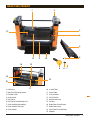
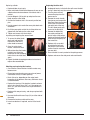
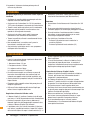
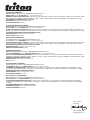
Planer / Thicknesser 317mm / 12.5"
Operating and
Safety Instructions
Gebrauchs- und
Sicherheitsanweisung
Bedienings- en
veiligheidsvoorschriften
Istruzioni Per L’uso E
La Sicurezza
Instructions d’utilisation et
consignes de sécurité
Instrucciones
de uso y de seguridad
www.tritontools.com
TPT 125
Thank you for purchasing this Triton tool. Please read these instructions: they contain information necessary for safe and
effective operation of this product. This product has a number of unique features and, even if you are familiar with similar
products, reading the instructions will help you get the full benefit of its unique design. Keep these instructions close to hand
and ensure all users of this tool have read and fully understand them.
CONTENTS
Specifications 2
Symbols 2
Know your product
3
Safety instructions
4
Assembly 6
Safety6
Preparation7
Operation
8
Maintenance
9
Troubleshooting11
Warranty 12
Declaration of Conformity
SPECIFICATIONS
Model no: TPT125
Voltage: 220V - 240V
Power: 1100W / 1.5hp
Cuts per min: 17,500min-1
Cutter head speed: 8750min-1
Planing height: 3.2mm x 152mm (0.1 x 6")
Planing width: 317mm / 12.5"
Table size: 317mm (12.5") x 238mm (9.37")
Insulation: Earthed
Net weight: 29 kg (63.9 lbs)
SYMBOLS
GB
ENVIRONMENTAL PROTECTION
Waste electrical products should not be disposed of with household waste. Please recycle where facilities exist. Check with your local authority or retailer for recycling advice.
WARNING. To reduce the
risk of injury, user must read instruction manual
Instruction warning.
Always wear ear, eye and respiratory protection.
Conforms to relevant legislation
and safety standards.
Contents / Specifications / Symbols
Class I construction (Protective earth).
KNOW YOUR PRODUCT
1
2
3
13
4
5
12
14
11
6
10
15
9
8 7
19
16
18
1.Rollercase
2.Side Panel Retaining Screws
3.Elevation Scale
4.Scale Pointer
5.Dust Chute
6.Dust Chute Thumb Screws (x2)
7. Crank Handle Retaining Bolt
8.Crank Handle Fixing Cap
9.Crank Handle
17
10. In-feed Table
11. Centre Table
12. Circuit Breaker
13. On/Off Switch
14. Brush Access Cap
15. Hex Key
16. Blade Cover Panel Screws
17. Blade Cover Panel
18. Dust Chute Fixing Positions
19. Magnets
Know your Product
GB
3
SAFETY INSTRUCTIONS
GB
WARNING Read all safety warnings and all
instructions. Failure to follow the warnings and
instructions may result in electric shock, fire and/
or serious injury.
Save all warnings and instructions for future
reference.
The term "power tool" in the warnings refers to your
mains-operated (corded) power tool or batteryoperated (cordless) power tool.
1) Work area safety
a) Keep work area clean and well lit. Cluttered or dark
areas invite accidents.
b) Do not operate power tools in explosive
atmospheres, such as in the presence of
flammable liquids, gases or dust. Power tools
create sparks which may ignite the dust or fumes.
c) Keep children and bystanders away while
operating a power tool. Distractions can cause you
to lose control.
2) Electrical safety
a) Power tool plugs must match the outlet. Never
modify the plug in any way. Do not use any
adapter plugs with earthed (grounded) power
tools. Unmodified plugs and matching outlets will
reduce risk of electric shock.
b) Avoid body contact with earthed or grounded
surfaces, such as pipes, radiators, ranges and
refrigerators. There is an increased risk of electric
shock if your body is earthed or grounded.
c) Do not expose power tools to rain or wet
conditions. Water entering a power tool will increase
the risk of electric shock.
d) Do not abuse the cord. Never use the cord for
carrying, pulling or unplugging the power tool.
Keep cord away from heat, oil, sharp edges or
moving parts. Damaged or entangled cords increase
the risk of electric shock.
e) When operating a power tool outdoors, use an
extension cord suitable for outdoor use. Use of
a cord suitable for outdoor use reduces the risk of
electric shock.
f) If operating a power tool in a damp location is
unavoidable, use a residual current device (RCD)
protected supply. Use of an RCD reduces the risk of
electric shock.
NOTE: The term “residual current device (RCD)”
may be replaced by the term “ground fault circuit
interrupter (GFCI)” or “earth leakage circuit breaker
(ELCB)”.
4
Safety Instructions
3) Personal safety
a) Stay alert, watch what you are doing and use
common sense when operating a power tool. Do
not use a power tool while you are tired or under
the influence of drugs, alcohol or medication. A
moment of inattention while operating power tools
may result in serious personal injury.
b) Use personal protective equipment. Always wear
eye protection. Protective equipment such as dust
mask, non-skid safety shoes, hard hat, or hearing
protection used for appropriate conditions will reduce
personal injuries.
c) Prevent unintentional starting. Ensure the switch
is in the off-position before connecting to power
source and/or battery pack, picking up or carrying
the tool. Carrying power tools with your finger on the
switch or energising power tools that have the switch
on invites accidents.
d) Remove any adjusting key or wrench before
turning the power tool on. A wrench or a key left
attached to a rotating part of the power tool may result
in personal injury.
e) Do not overreach. Keep proper footing and balance
at all times. This enables better control of the power
tool in unexpected situations.
f) Dress properly. Do not wear loose clothing or
jewellery. Keep your hair, clothing and gloves
away from moving parts. Loose clothes, jewellery or
long hair can be caught in moving parts.
g) If devices are provided for the connection of dust
extraction and collection facilities, ensure these
are connected and properly used. Use of dust
collection can reduce dust-related hazards.
4) Power tool use and care
a) Do not force the power tool. Use the correct power
tool for your application. The correct power tool will
do the job better and safer at the rate for which it was
designed.
b) Do not use the power tool if the switch does not
turn it on and off. Any power tool that cannot be
controlled with the switch is dangerous and must be
repaired.
c) Disconnect the plug from the power source and/
or the battery pack from the power tool before
making any adjustments, changing accessories,
or storing power tools. Such preventive safety
measures reduce the risk of starting the power tool
accidentally.
d) Store idle power tools out of the reach of children
and do not allow persons unfamiliar with the
power tool or these instructions to operate the
power tool.Power tools are dangerous in the hands of
untrained users.
e) Maintain power tools. Check for misalignment or
binding of moving parts, breakage of parts and
any other condition that may affect the power
tool’s operation. If damaged, have the power tool
repaired before use. Many accidents are caused by
poorly maintained power tools.
f) Keep cutting tools sharp and clean. Properly
maintained cutting tools with sharp cutting edges are
less likely to bind and are easier to control.
g) Use the power tool, accessories and tool bits etc.
in accordance with these instructions, taking into
account the working conditions and the work to
be performed. Use of the power tool for operations
different from those intended could result in a
hazardous situation.
5) Service
a) Have your power tool serviced by a qualified repair
person using only identical replacement parts.
This will ensure that the safety of the power tool is
maintained.
Cutting tool safety
For safety relating to protective clothing/equipment and
general health hazards relating to power tools, refer to
General and Electrical Safety sections in this manual
Use the correct cutting tool
• Ensure the cutting tool is suitable for the job. Do not
assume a tool is suitable without checking the product
literature before use.
Protect your eyes
• Always wear appropriate eye protection when using
cutting tools
• Spectacles are not designed to offer any protection
when using this product; normal lenses are not impact
resistant and could shatter
Protect your hearing
• Always wear suitable hearing protection when tool
noise exceeds 80dB
Protect your breathing
• Ensure that yourself, and others around you, wear
suitable dust masks
Be aware of others around you
• It is the responsibility of the user to ensure that other
people in the vicinity of the work area are not exposed
to dangerous noise or dust and are also provided with
suitable protective equipment
Hidden objects
• Inspect the workpiece and remove all nails and other
embedded objects before cutting
• Do not attempt to cut material that contains embedded
objects unless you know that the cutting tool fitted to
your machine is suitable for the job
• Walls may conceal wiring and piping, car body panels
may conceal fuel lines, and long grass may conceal
stones and glass. Always check the work area
thoroughly before proceeding
Beware of projected waste
• In some situations, waste material may be projected at
speed from the cutting tool. It is the users responsibility
to ensure that other people in the work area are
protected from the possibility of projected waste
Fitting cutting tools
• Ensure cutting tools are correctly and securely fitted
and check that wrenches / adjusters are removed prior
to use
• Only use cutting tools recommended for your machine
• Do not attempt to modify cutting tools
Direction of feed
• Always feed work into the blade or cutter against the
direction of movement of the blade or cutter
Beware of heat
• Cutting tools and workpieces may become hot in use.
Do not attempt to change tools until they have been
allowed to cool completely
Control dust / swarf
• Do not allow dust or swarf to build up. Sawdust is a fire
hazard, and some metal swarf is explosive
• Be especially careful when cutting wood and metal.
Sparks from metal cutting are a common cause of wood
dust fires
• Where possible, use a dust extraction system to ensure
a safer working environment
GB
Safety Instructions
5
ASSEMBLY
Unpacking
Carefully unpack and inspect your tool. Familiarise
yourself with all its features and functions.
Ensure that all parts of the tool are present and in good
condition. If any parts are missing or damaged, have such
parts replaced before attempting to use this tool.
Bench mounting
• Set up the unit on a firm,
flat surface so that the
table is horizontal and the
unit cannot tip over
• When siting the tool in a
permanent position, ensure
that it is fixed to a rigid
Fig.1
work surface
1. Use the holes in the base
of the planer/thicknesser as a template to mark and
drill four holes in your intended mounting surface (i.e.
workbench). Secure the unit in position using large
bolts, washers and nuts (not supplied)
2.If the planer/thicknesser is intended to be portable, fix
a board to the base which can be easily clamped and
removed from various mounting surfaces
3.Ensure bolts are long enough to penetrate the
workbench or board sufficiently for a secure fix
Attaching the crank handle
Mount the Crank Handle (9) in position (see main image)
on the right hand side of the planer:
1. Thread spring washer onto
Fig.2
Crank Handle Retaining Bolt
(7)
2.Fit the crank handle onto
the gear screw
3.Use the bolt to secure the
crank handle in position.
Use the Hex Key (15) to
tighten the bolt
4.Insert the Crank Handle Fixing Cap (8) to conceal the
fixing
Attaching the dust chute
The Dust Chute (5) can be mounted for extraction of
waste at either end of the planer
1. Use the 2 x Dust Chute
Thumb Screws (6) to mount
the dust chute onto the
Rollercase (1) using the Dust
Chute Fixing Positions (18)
2.Having fixed the chute in
position, connect the dust
extraction hose
Fig.3
3.Turn the extract system on
before operating the planer
SAFETY
GB
Important guidance for safe use of this tool
• Disconnect the machine from power source whenever
adjusting or replacing any parts
• Ensure the On/Off Switch is in the 'OFF' position before
connecting the tool to mains power
• Keep hands away from all moving parts
• Wear eye protection and a face mask when using this
tool
• Make sure all mobile parts move freely and are free
from interference
• Keep blades sharp, aligned and correctly secured to the
cutter head
• Never turn the machine on with the workpiece in
contact with the blades
• Whenever the planer is not in use, switch off and
disconnect from power
• Keep the planer in good order. Follow the maintenance
instructions (see 'Maintenance')
6
Assembly / Safety
Circuit breaker
• A circuit breaker is installed next to the On/Off Switch
(13)
• If excessive electric current is detected, the circuit
breaker will shut off the power supply to protect the
motor
• Before resetting the circuit breaker check the motor,
switch, and power connection for short circuit or faulty
components
• To reset the circuit breaker:
- Press the red (0) button so that the machine is turned off
- Press the Circuit Breaker Reset Button (12)
PREPARATION
Capacity
• Workpieces must comply with the following minimum
and maximum dimensions:
i. Min thickness: 3.2mm
ii. Min length: 125mm
iii. Min width: 18mm
iv. Max width: 317mm
• To prevent kickback, do not use a workpiece that is
warped, contains knots, or is embedded with foreign
objects (nails, staples, etc)
• This planer is designed for natural wood material only
• Remove glue and any foreign objects from the
workpiece before planing
• Measure and compare results to check that the blades
are correctly aligned and/or to determine the amount
of correction required
• If the blades need to be re-aligned, see 'Maintenance
– Re-aligning the rollercase' for guidance
Setting the depth of cut
• To protect the motor and cutter head, the
recommended maximum depth of cut for a single pass
is as follows:
Max Depth of Cut
Width of workpiece
Max depth of cut
• Use the entire width of the cutter head to avoid uneven
wear of blades
Up to 125mm
2.38mm
From 125mm up to 317mm
1.6mm
Rollercase height adjustment
To set the depth of cut:
• The Rollercase (1) contains the motor, cutting head
with blades, and the in-feed and out-feed rollers
1. Measure the current thickness of the workpiece, and
compare with required thickness
• Rotate the Crank Handle (9) to raise or lower the
rollercase. One complete turn of the crank handle
raises or lowers the rollercase 1.58mm (1/16")
2.Refer to the 'Max Depth of Cut' table above to
determine whether one or more passes are required
• The Scale Pointer (4) and Elevation Scale (3) provide
a reading, in metric and imperial graduations, of the
height of the cutter head above the Centre Table
(11) – and therefore the approximate thickness of the
workpiece after planing
• Use the crank handle to move the rollercase up
or down until the Scale Pointer (4) indicates, on
the Elevation Scale (3), the finished thickness of
workpiece required
• The elevation scale is calibrated at the factory. For
precision woodworking, it is recommended that
you check the dimension with calipers or a digital
thickness gauge before and after each cutting pass
Checking the rollercase is level
• The rollercase is aligned and checked in the factory.
However, it can become out of alignment during
shipping and handling
• If the rollercase is not level with the Centre Table (11),
this will result in a tapered cut where the thickness on
each side of the workpiece differs. It can also cause
uneven wear of the blade
• To check that the blades are aligned correctly; run two
pieces through each side (left and right) of the planer
3.If just one pass is required:
4.If more than one pass will be required:
a) It is recommended that you divide the total required
into passes of approximately equal depth
b) For the first and any intermediate cuts, set the height
of the rollercase at current workpiece thickness minus
depth calculated in step (a) above
c) Check measurements after each cut with callipers or a
digital thickness gauge
Switching on and off
GB
• The On/Off Switch (13) is located on the front of the
planer
• To turn the planer ON, press the green ON (I) button
• To turn the planer OFF, push the red OFF (0) button
Preparation
7
OPERATION
For best results
• Determine required depth of cut and final thickness
of workpiece before planing. Since there is a limit to
maximum depth of cut, several passes may be required
to achieve final thickness
• In general, thin cuts produce a better outcome in terms
of smoothness of finished surface, even thickness, less
kickback, less snipe, and less wear on the cutter head
and motor
• To prevent kickback, never make cuts deeper than
2.4mm (3/32") in one pass
• If more than one pass is necessary, the rollercase must
be lowered manually before each pass
• Always set a thin depth of cut for hardwood, wide
workpieces and workpieces with an uneven surface
• Avoid wood stock with many or large knots, or with
excessive twisting, cupping, or bowing
• If necessary, process one side with a jointer or surface
planer first to obtain at least one flat surface before
using the planer
• Plane both sides of the workpiece, removing half the
total depth from each side. This will produce two
smooth surfaces with equal moisture content and
therefore a board less likely to warp when it dries
naturally
• Make a test cut with similar material to check accuracy
of the settings before planing the workpiece
• Feed the workpiece 'with' the grain whenever possible
• Provide suitable support for long or wide workpieces
GB
Operating the planer
1. Set up the planer for depth of cut required (see
'Preparation' above)
2.Put on all safety equipment required to use this tool,
including face mask and safety glasses
3.Never stand directly in front of the workpiece, stand to
the side of the crank handle. and do not allow anyone
to stand or cross in line with blade rotation. Kickback
or thrown debris will travel in this direction
4.Place the workpiece on the In-feed Table (10), with the
surface to be planed facing upwards
5.Turn the machine on and allow the cutter head to reach
full speed
6.Holding the workpiece firmly, move it slowly towards
and onto the in-feed roller
NOTE: Never feed a workpiece into the planer via the
out-feed table
8
Operation
7. Stop pushing the workpiece once it is engaged by the in-feed roller. The in-feed roller will move the workpiece automatically through the planer
8.Do not force the cut. Slowing or stalling will overheat the motor
9.Always keep your hands well away from the blades or
chip ejection area while the motor is running
10.Support the weight of large workpieces as they move through the planer to stabilise the workpiece and reduce snipe
11.Move to the back of machine to receive the workpiece, Do not pull the workpiece; allow the rollers to do the work
12.If a workpiece should become jammed inside the machine: turn the machine off, remove the plug from mains supply, raise the rollercase away from the workpiece and ALLOW THE MACHINE TO COME TO A COMPLETE STOP
13.Never reach into the machine whilst it is in operation or running down
14.Use in-feed and out-feed rollers or supports when working with long workpieces
15.For precision woodworking, measure the thickness of the workpiece with calipers or a digital thickness gauge after each pass
MAINTENANCE
WARNING! Always ensure that the tool is switched off and
the plug is removed from the power point before making
any adjustments or carrying out maintenance
• Any damage to this tool should be repaired and
carefully inspected before use, by qualified repair
personnel
• Have your power tool serviced by a qualified repair
person using only identical replacement parts. This will
ensure that the safety of the power tool is maintained
Cleaning and lubrication
• After use, vacuum the planer machine to remove wood
chips, sawdust and debris
• Use a cleaning solution (not included) to remove resin
and grease residue
• Remove sawdust, wood chips and grease from chains
and gears
• The bearings in motor and cutter head units are
factory-sealed and should require no further lubrication
• Four components require regular lubrication:
- Rollercase vertical screw mechanism (x2)
- Rollercase lock cam
- Rollercase vertical rails (x4)
- Feed roller chain drive
• Remove the top and both side panels to access these
components
• Clean the chain drive before lubrication. Use spray oil
(not included) to lubricate the chain. Allow time for the
lubricant to penetrate between the links, then wipe the
surface of the chain dry
• Remove any residues of grease from the other
components, using mineral spirits if necessary, then
apply a coat of light grade multi-purpose grease (not
included)
• The work table and extension table can be coated with
a very thin coat of lubricating wax (not included) to
protect the surface from rust and to facilitate smooth
feed during operation
Re-aligning the rollercase
• Test the blade alignment by
running two pieces through
each side (left and right) of
the planer
• Measure and compare
results to check that the
blades are correctly aligned
and/or to determine the
amount of correction
required
Fig.4
• To correct any misalignment:
1. Turn the planer off and
Fig.5
remove the plug from the
power source
2.Carefully place the planer on
its back
3.Remove the screws to the
horizontal spindle retaining
bracket on the Crank Handle
(9) side of the planer.
4.Carefully disengage the gears
5.Slowly rotate the crank handle to raise or lower the
rollercase as needed to re-position it on the vertical
screw
6.Rotate the crank handle forward or back as required in
order to correct the misalignment. Each complete turn
of the crank handle will make an adjustment of 0.15mm
(0.006")
7. Re-engage the gears and re-fit the horizontal spindle
retaining bracket
8.Carefully sit the planer upright again
9.Carry out a test run to check the rollercase is now level
10.Repeat the correction process if further adjustment is necessary
Checking and replacing the blades
Inspecting the blades:
1. Locate the Blade Cover Panel (17) on the back of
planer. Loosen and remove the thumb screws on either
side and lift off the panel
2.Identify the cutter head inside, and the TWO sharp
blades on the cutter head
3.Without touching the blades, carefully turn the cutter
head until the self-engaging
Fig.6
latch clicks to lock the
cutter head.
4.Use the Hex Key (15) to
remove the six bolts on the
blade cover plate
5.Using the two Magnets (19),
carefully remove the blade
cover plate
6.Then use the magnets to
Fig.7
remove the blade
7. Inspect the blade for signs
of wear or damage. A blade
that is dull, worn, nicked,
torn or uneven can result
in poor performance such
as fuzzy, chipped or raised
grain, raised edge and
uneven cut
Maintenance
9
GB
Replacing a blade:
• Replace blades in pairs only
• Never mix blades with different degrees of wear or use
a blade where unbalanced wear from side to side is
evident
1. Use the Magnets (19) to pick up and place the new
blade onto the cutter head
2.Position the blade so that it sits securely on the two
pins
3.Use the magnets to transfer the cover plate back onto
the blades
4.Re-fit the cover plate so that the six fixing holes are
aligned with the holes on the cutter head
5.Tighten and secure with the six bolts
Inspecting and replacing the second blade:
1. To access the other blade,
Fig.8
gently pull and hold the
latch on the side of the
cutter head to release it
2.Once the cutter head
rotates, release the latch
3.Without touching the blades,
carefully turn the cutter
head until the self-engaging
latch clicks to lock the head
again
4.Repeat the blade changing procedure to check and
replace the second blade
GB
Checking and replacing the brushes
• Over time the carbon brushes inside the motor may
become worn
• Excessively worn brushes may cause loss of power,
intermittent failure, or visible sparking
• Brush life varies, depending on the motor loads.
Inspection of the brushes after every 100 hours of use
is recommended
• Replace the brushes if the length of carbon has been
worn to less than 9.5mm (3/8"), or if the springs are
worn, or if you have noticed a loss of performance in
the motor
• Replace with new parts only, and always replace both
brushes
1. Unscrew the Brush Access Caps (14) on either side of
the motor
2.Remove the brushes and check for wear
3.Insert new brushes if required, and re-fit the brush
caps
10
Maintenance
Replacing the drive belt
• Inadequate tension in the belt drive will cause the belt
to slip. A loose belt must be replaced
1. Turn the planer off and
Fig.9
remove the plug from the
power source
2.Remove the crank handle,
then loosen and remove the
Side Panel Retaining Screws
so that you can move the
side panel out of the way.
This will allow you to gain
access to the belt drive
3.Remove the old belt by
Fig.10
alternately walking the
belt off each of the pulleys.
Gently pull the belt outward
while turning the pulleys at
the same time
4.Replace with a new belt
by walking the belt onto
the pulleys in the reverse
manner used for removing
the worn belt
5.Ensure the belt is evenly seated on the pulley grooves
6.Replace and secure the side panel and crank handle
TROUBLESHOOTING
SYMPTOM
PROBLEM
SUGGESTED REMEDY
Motor overheats
Motor overloaded
Reduce load on motor. Turn off the machine
until motor cools down
Excessive dust build-up results in
decreased air circulation
Remove dust build-up
Motor overload
Reduce load on motor
Inadequate capacity of circuit breaker
Replace with correct circuit breaker
Circuit overload
Reduce circuit load
Frequent tripping of circuit
breaker
Snipe
Planed surface not smooth
Difficulties in adjusting
rollercase height
Blades are dull
Sharpen or replace blades
Inadequate support of workpiece
Support long workpiece with additional
platform
Blades are dull
Replace blades
Uneven force on cutterhead
Push workpiece gently during operation
Rollercase is not parallel with table
Adjust table and rollercase level correctly
Workpiece is not butted correctly
Butt end to end each workpiece as it passes
through planer
Blades are dull
Replace blades
Fuzzy grain due to high moisture
content in wood
Use dry wood
Torn grain due to blades cutting
against grain
Change direction and feed workpiece along
the grain
The cut is too deep
Decrease depth of cut
Uneven thickness from side to side
Rollercase is not positioned level with planer
base. Adjust rollercase alignment
Rollercase lock is engaged
Release rollercase lock
Worn elevation screws
Replace elevation screws
Dirty elevation screws
Clean and lubricate elevation screws
Rollercase is not positioned parallel
with table
Re-align rollercase
Friction between rollercase and side
panels
Clean and adjust rollercase
GB
Troubleshooting
11
WARRANTY
To register your guarantee visit our web site at
www.tritontools.com* and enter your details.
Your details will be included on our mailing list (unless
indicated otherwise) for information on future releases.
Details provided will not
be made available to any third party.
PURCHASE RECORD
Date of Purchase:
___ / ___ / ____
Model: TPT125
Serial Number: __________________
Retain your receipt as proof of purchase
GB
12
Warranty
Triton Precision Power Tools guarantees to the
purchaser of this product that if any part proves to
be defective due to faulty materials or workmanship
within 12 MONTHS from the date of original
purchase, Triton will repair, or at its discretion
replace, the faulty part free of charge.
This guarantee does not apply to commercial use
nor does it extend to normal wear and tear or
damage as a result of accident, abuse or misuse.
* Register online within 30 days.
Terms & conditions apply.
This does not affect your statutory rights
Grazie per aver acquistato questo utensile Triton. Queste istruzioni contengono informazioni utili
per il funzionamento sicuro ed affidabile del prodotto.
Per essere sicuri di utilizzare al meglio il potenziale dell'utensile si raccomanda pertanto di leggere a fondo questo manuale.
Conservare il manuale in modo che sia sempre a portata di mano e accertarsi che l'operatore dell'elettroutensile lo abbia letto
e capito a pieno.
INDICE
Caratteristiche tecniche Familiarizzazione
Norme generali di sicurezza Simboli
Montaggio Sicurezza
Preparazione
Funzionamento Manutenzione
Risoluzione di problemi
44
44
45
46
46
48
48
49
50
52
Garanzia 53
CARATTERISTICHE TECNICHE
Numero di prodotto: TPT125
Tensione: 220 V – 240 V
Potenza: 1100 W / 1,5 CV
Numero di tagli per minuto: 17500
Velocità della testa di taglio: 8750 min-1
Altezza di piallatura: 3,2 mm – 152 mm
Max. larghezza di piallatura: 317 mm
Dimensione della tavola: 317 x 320 mm
Isolamento: doppio isolamento
Peso netto: 29 kg
FAMILIARIZZAZIONE
I
1. Blocco di taglio
2. Viti di fissaggio del pannello laterale
3. Scala di elevazione
4. Puntatore scala
5. Tubo anti-polvere
6. Viti per il tubo anti-polvere (x2)
7. Bullone di fissaggio per manovella
8. Tappo di fissaggio per manovella
9. Manovella
10. Tavola di alimentazione
44
11. Tavola centrale
12.Pulsante di reset contattore
13. Interruttore On / Off
14. Cappuccio di accesso spazzola
15. Chiave esagonale
16. Viti del pannello di copertura della lama
17. Pannello di copertura della lama
18. Posizioni di fissaggio del tubo anti-polvere
19. Magneti
Indice / Caratteristiche Tecniche / Familiarizzazione
NORME GENERALI DI SICUREZZA
AVVERTENZA: Leggere ed assimilare tutte
le istruzioni. La non osservanza delle seguenti
istruzioni può causare scosse elettriche, incendi
e/o lesioni gravi.
Conservare tutte le avvertenze di pericolo e le
istruzioni operative per ogni esigenza futura.
Il termine “elettroutensile” si riferisce all’utensile a
rete fissa (con filo) o un utensile a batteria (senza filo).
1. Area di lavoro.
a. Mantenere l’area di lavoro pulita e adeguatamente
illuminata. Il disordine e le zone di lavoro non
illuminate possono essere fonte di incidenti.
b. Non usare gli elettroutensili in presenza di
atmosfere esplosive, come liquidi, gas e polveri
infiammabili. Gli elettroutensili producono scintille
che potrebbero accendere le polveri o i fumi.
c. Tenere altre persone e i bambini a distanza di
sicurezza durante l’impiego dell’utensile elettrico.
Eventuali distrazioni potrebbero far perdere il controllo
dell’utensile all’operatore.
2. Sicurezza elettrica
a. Le spine degli elettroutensili devono essere
compatibili con le prese di corrente.
Non modificare in alcun modo la spina
dell’elettroutensile. Non usare adattatori con gli
elettroutensili dotati di collegamento di messa
a terra. L’uso delle spine originali non modificate e
delle prese corrispondenti ridurrà il rischio di scosse
elettriche.
b. Evitare il contatto del corpo con le superfici
collegate a massa come i tubi, i radiatori, le
cucine e i frigoriferi. Se il corpo dell’operatore è
collegato alla terra o alla massa il rischio di scosse
elettriche è maggiore.
c. Non esporre gli elettroutensili alla pioggia e non
lasciarli in ambienti umidi o bagnati. L’ingresso
dell’acqua in una macchina utensile aumenta il rischio
di scosse elettriche.
d. Non usare il cavo in modo improprio. Non afferrare
mai il cavo per trasportare, tirare o staccare
l’elettroutensile dalla presa di corrente. Tenere il
cavo lontano da fonti di calore, olio, e sostanze
affini, bordi appuntiti o parti in movimento. I cavi
danneggiati o attorcigliati aumentano il rischio di
scosse elettriche.
e. Qualora si voglia usare l’utensile all’aperto, usare
cavi di prolunga compatibili con l’uso in ambienti
esterni. Un cavo idoneo all’uso in ambienti esterni
riduce il rischio di scosse elettriche.
f. Se l’utilizzo di un elettroutensile in ambiente
umido è inevitabile, utilizzare una fonte di
alimentazione protetta da un dispositivo
differenziale. L’uso di un dispositivo differenziale
riduce notevolmente il rischio di scosse elettriche.
NOTA : Il termine "dispositivo di corrente residua
(RCD)" può essere sostituita dal termine "circuito
di guasto a terra (GFCI) "o" dispersione a terra
interruttore (ELCB) ".
3. Sicurezza personale
a. Quando si usa un elettroutensile lavorare sempre
con la massima attenzione e concentrazione,
lasciandosi guidare dal buon senso. Non usare
mai un elettroutensile quando si è stanchi o sotto
l’effetto di medicinali e/o sostanze alcoliche o
stupefacenti. Quando si usa un elettroutensile un
attimo di distrazione è sufficiente a causare gravi
lesioni alle persone.
b. Usare dispositivi per la protezione personale.
Indossare sempre protezioni per gli occhi. I
dispositivi per la sicurezza personale, come le
mascherine antipolvere, le calzature di sicurezza
antiscivolo, il casco e la cuffia, se usati in maniera
appropriata, riducono i rischi di lesioni alle persone.
c. Evitare l’avviamento accidentale. Garantire che
l’interruttore è in posizione arresto (OFF) prima
di attaccare la presa. Trasportare gli elettroutensili
con il dito al di sopra dell’interruttore o attaccando
l’elettroutensile con l’interruttore acceso, aumenta il
rischio di accidenti.
d. Rimuovere tutte le chiavi di regolazione e le chiavi
inglesi prima di accendere l’elettroutensile. Una
chiave inglese o una chiave di regolazione collegata a
una parte in movimento dell’elettroutensile potrebbe
causare lesioni alle persone.
e. Non andare oltre l’altezza consentita. In qualsiasi
momento mantenere i piedi poggiati su superfici
solide e un punto di appoggio sicuro. Un buon
equilibrio consente di avere il massimo controllo
sull’elettroutensile nelle situazioni inaspettate.
f. Vestirsi con abbigliamento adeguato. Non indossare
abiti larghi o gioielli. Tenere i capelli, vestiti e guanti
lontano da parti in movimento.
g. Se il dispositivo utilizzato è dotato di bocchetta
per l’aspirazione della polvere accertarsi che sia
collegato e utilizzato correttamente. L’uso di tali
dispositivi riduce i rischi correlati alle polveri.
4. Maneggio ed impiego accurato di utensili elettrici
a. Non forzare l’elettroutensile. Usare sempre
l’elettroutensile corretto per il lavoro da eseguire.
L’elettroutensile corretto sarà in grado di svolgere il
lavoro in modo più efficiente e sicuro nell’ambito della
gamma di potenza indicata.
I
Norme generali di sicurezza 45
b. Non usare l’elettroutensile se l’interruttore
di accensione non si accende e si spegne. Gli
elettroutensili con un interruttore di accensione
difettoso sono pericolosi e devono essere riparati
immediatamente.
c. Staccare la spina dalla presa di corrente prima
di effettuare qualsiasi regolazione, sostituire gli
accessori o riporre gli attrezzi a motore. Queste
misure di sicurezza preventive riducono il rischio di
avvio involontario.
d. Conservare l’elettroutensile fuori dalla portata
dei bambini e non lasciare che venga utilizzato
da persone non adeguatamente addestrate e
competenti nell’uso degli elettroutensili o che
non abbiano letto questo manuale di istruzioni. Gli
elettroutensili diventano estremamente pericolosi nelle
mani di persone non addestrate.
e. Mantenere gli elettroutensili. Controllare per
disallineamento o la legatura delle parti in
movimento, la rottura di parti e altre condizioni che
possono influire il funzionamento dell’apparecchio.
In caso di danneggiamento, fare riparare prima
dell’uso. Molti incidenti sono causati da una scarsa
manutenzione dell’utensile.
f. Mantenere le lame pulite e affilate. Gli utensili da
taglio tenuti in buone condizioni operative e con i bordi
taglienti affilati sono meno soggetti a bloccarsi e più
facili da controllare.
g. Utilizzare l’elettroutensile e tutti i componenti e gli
accessori in conformità con le istruzioni di questo
manuale e nella maniera prevista per ciascun
tipo di utensile, tenendo conto delle condizioni
lavorative e del compito da eseguire. L’utilizzo
degli elettroutensili per fini diversi da quelli previsti
rappresenta un rischio per le persone.
5. Assistenza
a. Qualsiasi intervento sull’elettroutensile deve
essere eseguito da personale qualificato
utilizzando unicamente pezzi di ricambio
compatibili e approvati. Ciò garantisce la sicurezza
dell’utensile elettrico.
I
Sicurezza su utensili da taglio
Utilizzare lo strumento da taglio corretto
• Assicurarsi che l'utensile da taglio è adatto per il
lavoro. Non date per scontato che lo strumento sia
adatto senza controllare la documentazione del
prodotto prima dell'uso.
Protezioni Occhi
• Indossare sempre una protezione adeguata per gli
occhi quando si utilizzano utensili da taglio
• Occhiali di tutti i giorni non sono progettati per offrire
alcuna protezione quando si utilizza questo prodotto;
lenti normali non sono resistenti agli urti e potrebbero
frantumarsi
46
Norme generali di sicurezza
Protezione Respiratorie
• Assicurarsi che voi stessi ed altri intorno a te, indossino
mascherine antipolvere adatte
Protezione dell’udito
• Indossare sempre un'adeguata protezione dell'udito
quando il rumore dell’utensile supera i 80 dB.
Essere consapevoli di altri intorno a te
• È la responsabilità dell'utente assicurarsi che altre
persone in prossimità dell'area di lavoro non sono
esposti a rumori pericolosi o polvere e sono inoltre
dotati di idonei dispositivi di protezione
Attenzione ai rifiuti proiettati
• In alcune situazioni, i rifiuti possono essere proiettati
a velocità da taglio. Assicurarsi che non ci siano altre
persone all'interno dell'area di lavoro. Se è necessario
avere altre persone nelle vicinanze, è responsabilità
dell'utente assicurarsi che essi sono dotati con
attrezzatura di protezione corrette.
Montaggio di utensili da taglio
• Garantire che utensili da taglio siano correttamente e
saldamente fissati e verificare che chiavi / regolatori
sono stati rimossi prima dell'uso
• Utilizzare solo utensili da taglio consigliati per la vostra
macchina
• Non tentare di modificare gli utensili da taglio
Direzione di avanzamento
• Sempre alimentare il lavoro nella lama o fresa contro la
direzione del movimento della lama o fresa.
Attenzione al calore
• Essere consapevoli del fatto che gli utensili e pezzi
di lavoror possono surriscaldarsi in uso. Non cercare
di cambiare gli strumenti fino a quando non è stato
consentito un raffreddamento completo
Oggetti estranei
• Ispezionare completamente i materiali da taglio per
qualsiasi forma di oggetti estranei prima del taglio.
• Non tentare di tagliare il materiale che contiene oggetti
estranei, a meno che non si sa che l'utensile da taglio
impostato alla vostra macchina è adatta per il lavoro
Oggetti nascosti
• Attenzione di oggetti nascosti. Pareti possono
nascondere cavi e tubazioni, pannelli di carrozzeria
può nascondere tubi del carburante, e l'erba alta può
nascondere pietre e vetro. Controllare sempre l'area di
lavoro a fondo prima di procedere
Controllo delle polveri / trucioli
• Non permettere a polvere o trucioli di accumularsi.
Segatura è un pericolo di incendio, ed alcuni trucioli di
metallo sono esplosivi
• Prestare particolare attenzione con macchine usate per
tagliare legno e metallo. Scintille da taglio dei metalli
sono una causa comune di incendi dalla polvere di
legno
• Dove possibile, utilizzare un sistema di aestrazione
polvere per garantire un ambiente di lavoro più sicuro
SIMBOLI
PROTEZIONE AMBIENTALE
Il simbolo del cestino barrato indica che il prodotto, una volta diventato inservibile, non deve essere gettato tra i rifiuti domestici ma conferito ad un centro di raccolta differenziata per apparecchi elettrici ed elettronici oppure riconsegnato al rivenditore al momento dell’acquisto di apparecchio sostitutivo.
Indossare sempre protezioni per gli occhi e per le vie respiratorie.
Nota nelle istruzioni.
Avvertenza
Costruzione della classe I (terra protettiva).
Il prodotto è conforme alle vigenti normative e norme di sicurezza applicabili
MONTAGGIO
Disimballaggio
Rimuovere tutto il materiale da dentro ed intorno la
piallatrice
Montaggio banco
• Impostare l'unità su una
superficie solida, piana,
in modo che il banco è
orizzontale e l'unità non
può ribaltarsi
• Se la piallatrice deve essere
utilizzata in una posizione
permanente, si consiglia
Fig.1
di fissarla ad un piano di
lavoro rigido:
1. Utilizzare i fori alla base della piallatrice come modello
per segnare e praticare quattro fori nella vostra
superficie destinata al montaggio (es. banco di lavoro).
Fissare l'unità in posizione con grandi bulloni, rondelle
e dadi (non forniti)
2. Se la piallatrice è destinata ad essere più portabile,
fissare un bordo alla base che può essere facilmente
bloccato e rimosso da varie superfici di montaggio
3. Se usando bulloni assicurarsi che siano abbastanza
lunghi per penetrare il banco da lavoro o bordo di
cartone sufficientemente per un montaggio sicuro
Attach the crank handle
Mount the Crank Handle (9) in position (see main image)
on the right hand side of the planer:
1. Infilare la rondella a molla
Fig.2
sul bullone di arresto
manovella (7)
2. Montare la manovella sulla
vite di marcia
3. Utilizzare il bullone per
fissare la manovella in
posizione. Utilizzare la
chiave esagonale (15) per
serrare il bullone
4. Inserire il tappo di fissaggio manovella (8) per
nascondere il fissaggio
Attaccare il condotto anti-polvere
Il condotto anti-polvere (12) può essere montato per
l'estrazione dei rifiuti alle due estremità della piallatrice
1. Utilizzare le 2 viti del tubo
anti-polvere per montare il
condotto anti-polvere sul
cilindro a rullo (1) usando
le posizioni di fissaggio del
tubo anti-polvere(18).
2. Dopo aver fissato il condotto
in posizione, collegare il
tubo del sistema estrazione Fig.3
Norme generali di sicurezza / Simboli / Montaggio 47
I
3. Accendere il sistema estrazione polvere prima di
utilizzare la piallatrice
SICUREZZA
Una guida importante per un utilizzo sicuro di questo
strumento
• Scollegare la macchina dalla corrente ogni volta che
regolate o sostituite eventuali parti
• Assicurarsi che l'interruttore On / Off è in posizione
'OFF' prima di collegare lo strumento alla rete elettrica
• Tenere le mani lontane da tutte le parti in movimento
• Indossare occhiali protettivi e una maschera viso
quando si utilizza questo strumento
• Assicurarsi che tutte le parti mobili si muovano
liberamente e che sono liberi da interferenze
• Tenere lame affilate, allineati e correttamente fissato
alla testa di taglio
• Non accendere mai la macchina con il pezzo in
lavorazione in contatto con le lame
• Ogni volta che la piallatrice non è in uso, spegnere e
scollegare dalla rete elettrica
• Mantenere la piallatrice in buon ordine. Seguire le
istruzioni di manutenzione (vedi 'Manutenzione')
Contatore
• Un contatore è installato accanto l’interruttore On / Off
(13)
• Se una corrente elettrica eccessiva viene rilevata, il
contatore spegnerà la corrente per proteggere il motore
• Prima di resettare il contatore controlla il motore,
interruttore, e connessione elettrica per un corto
circuito o per componenti difettosi
• Per ripristinare il contatore di circuito:
- Premere il (0) pulsante rosso in modo che la macchina è spenta
- Premere il pulsante di reset contatore (12)
PREPARAZIONE
Capacità
• I pezzi in lavorazione devono rispettare le dimensioni
minime e massime seguenti:
i. Spessore minimo: 3,2 mm
ii. Lunghezza minima: 125mm
iii. Larghezza minima: 18mm
iv. Larghezza massima: 317 millimetri
• Per evitare contraccolpi, non utilizzare un pezzo di
lavoro che viene deformato, che contiene nodi, o è
integrato con oggetti estranei (chiodi, graffette, ecc)
• Questa piallatrice è progettata solo per il materiale di
legno naturale
• Rimuovere colla e oggetti estranei dal pezzo prima di
eseguire la piallatura
• Utilizzare l'intera larghezza della testa di taglio per
evitare l'usura irregolare delle lame
I
Regolazione altezza del cilindro a rullo
• Il blocco di taglio (1) contiene il motore, testa di taglio
con lame, e i rulli di alimentazione e fuori alimentazione
• Ruotare la manovella (9) per alzare o abbassare il
blocco di taglio. Un giro completo della manovella alza
o abassa il blocco di taglio 1,58 millimetri
• Il puntatore scala (4) e scala di elevazione (3) fornisce
una lettura, in gradazioni metrica e imperiale, l'altezza
della testa di taglio al di sopra la tavola centrale (11) - e
48
Montaggio / Sicurezza / Preparazione
quindi lo spessore approssimativo del pezzo di lavoro
dopo la piallatura
• La scala di elevazione è calibrata in fabbrica. Per la
lavorazione del legno di precisione, si consiglia di
controllare la dimensione con pinze o uno spessimetro
digitale prima e dopo ogni passata di taglio
Controllo che il blocco di taglio è livello
• Il blocco di taglio è allineato e controllato in fabbrica.
Tuttavia, può essere fuori allineamento durante il
trasporto e la movimentazione
• Se il blocco di taglio non è in livello con la tavola
centrale (7), questo risultirà in un taglio affusolato dove
lo spessore su un lato del pezzo è diverso dall'altro. Può anche causare l'usura irregolare della lama
• Verificare che le lame siano allineate correttamente con
un giro di prova: eseguire due pezzi attraverso ogni lato
(destro e sinistro) della piallatrice
• Misurare e confrontare i risultati per verificare
che le lame siano correttamente allineate e / o per
determinare la quantità di correzione richiesta
• Se le lame devono essere ri-allineati, vedere
'Manutenzione - Re-allineamento del blocco di taglio'
come guida d’assistenza
Impostazione della profondità di taglio
• Per proteggere il motore e la testa di taglio, la
profondità massima di taglio consigliata per un singolo
passaggio è di seguito:
Profondità max di taglio
Larghezza del pezzo
in lavorazione Fino a 125 mm Da 125mm fino a 317 millimetri Profondità di taglio max
2,38 millimetri
1,6 millimetri
Per impostare la profondità di taglio:
1. Misurare lo spessore attuale del pezzo in lavorazione, e
confrontare con il spessore richiesto
2. Fare riferimento alla 'profondità massima di taglio'
tabella sopra riportata per determinare se uno o più
passaggi sono necessari
3. Se un solo passaggio è richiesto:
• Utilizzare la manovella per alzare o abbassare il blocco
di taglio fino a quando il puntatore scala (4) indica, sulla
scala di elevazione (4), lo spessore finale del pezzo in
lavorazione richiesto
4. Se più di un passaggio sarà necessario:
a) Si consiglia di dividere il totale richiesto in passaggi
approsimativamente pari di profondità
b) Per la prima e eventuali tagli intermedi, impostare
l'altezza del blocco di taglio a spessore del pezzo
corrente meno la profondità calcolata al punto (a)
c) Verificare misura dopo ogni taglio con pinze o uno
spessimetro digitale
Accensione e spegnimento
• L'interruttore On / Off (13) si trova sulla parte anteriore
della piallatrice
• Per attivare la piallatrice su ON, premere il tasto verde
ON (I)
• Per attivare la piallatrice su OFF, premere il tasto rosso
OFF (0)
FUNZIONAMENTO
Per ottenere i migliori risultati
• Determinare la profondità desiderata di taglio e
spessore finale del pezzo prima della piallatura. Poiché
vi è un limite alla massima profondità di taglio, diversi
passaggi possono essere necessari per raggiungere lo
spessore finale
• In generale, i tagli sottili producono un risultato migliore
in termini di levigatezza della superficie finita, anche
lo spessore, meno contraccolpo, meno beccaccino, e
minore usura della testa di taglio e il motore
• Per evitare contraccolpi, mai fare tagli più profondi di
2,4 millimetri (3 / 32 ") in un solo passaggio
• Se più di un passaggio sia necessario, il blocco di taglio
deve essere abbassato manualmente prima di ogni
passo
• Impostare sempre una profondità di taglio sottile
per il legno duro, pezzi di larghezza e pezzi con una
superficie irregolare
• Evitare legno di magazzino con molti nodi o con
torsione eccessivi, coppettazioni, o pezzi che si
inchinano
• Se necessario, passare un lato con una fresatrice a
giuntura o con una piallatrice a superficie prima per
ottenere almeno una superficie piana prima di usare la
piallatrice
• Passare la piallatrice su entrambi i lati del pezzo,
eliminando metà della profondità totale da ogni lato.
Questo produrrà due superfici lisce con contenuto di
umidità pari e quindi un consiglio meno probabilità di
ordito quando si asciuga naturalmente
• Fare un taglio di prova con materiale simile a verificare
l'esattezza delle impostazioni prima della piallatura del
pezzo
• Inserire il pezzo 'con' il grano quando possibile
• Fornire un supporto adatto per pezzi lunghi o larghi
Funzionamento della piallatrice
1. Impostare la piallatrice per la profondità di taglio
necessaria (vedi 'La preparazione' sopra)
2. Mettere su tutte le dotazioni di sicurezza necessarie
per utilizzare questo strumento, tra maschera e occhiali
di sicurezza
3. Stare dalla parte dove si trova la manovella. Mai stare
direttamente di fronte al pezzo, e non permettere a
nessuno di stare in piedi o attraversare in linea con
la rotazione delle lame. Contraccolpo o detriti gettati
viaggeranno in questa direzione
4. Posizionare il pezzo sul banco frontale (10) con la
superficie da piallato rivolto verso l'alto
5. Accendere la macchina e consentire alla testa di taglio
di raggiungere velocità
6. Tenendo saldamente il pezzo, muoverlo lentamente
verso e sul rullo di alimentazione
NOTA: Non alimentare un pezzo nella piallatrice via il
banco di fuori alimentazione (12)
7. Smettere di spingere il pezzo una volta che è ingaggiato
dal rullo in entrata. L'avanzamento a rulli muoverà il
pezzo automaticamente attraverso la piallatrice
Preparazione / Funzionamento 49
I
8. Non forzare il taglio. Rallentamento o interruzione
possono surriscalda il motore
9. Tenere sempre le mani ben lontani dalle lame o area
d’espulsione dei framenti, mentre il motore è in
funzione
10. Sostenere il peso di pezzi di grandi dimensioni mentre
si muovono attraverso la piallatrice per stabilizzare il
pezzo e ridurre i beccaccini
11. Spostarsi alla parte posteriore della macchina per
ricevere il pezzo in lavorazione, non tirare il pezzo;
permettere ai rulli di eseguire il loro lavoro
12. Se un pezzo dovrebbe diventare inceppato all'interno
della macchina: spegnere la macchina, togliere la
spina dalla rete di alimentazione, alzare il blocco di
taglio lontano dal pezzo e permettere alla macchina di
arrivare ad un COMPLETO ARRESTO.
13. Non avvicinarsi mai alla macchina mentre è in
funzione o mentre si sta fermando
14. Utilizzare rulli di entrata e di uscita o supporti quando
si lavora con pezzi lunghi
15. Per la lavorazione del legno di precisione, misura
lo spessore del pezzo con pinze o uno spessimetro
digitale dopo ogni passata
MANUTENZIONE
ATTENZIONE! Assicurarsi sempre che l'utensile sia
spento e che la presa viene rimossa dalla rete elettrica
prima di effettuare eventuali modifiche o manutenzioni
• Eventuali danni a questo strumento dovrebbero essere
riparati e accuratamente controllati prima dell'uso,
presso un personale specializzato di riparazione.
• Far revisionare l'utensile da una persona personale
specializzata usando solo pezzi di ricambio identici.
Questo assicurerà che la sicurezza dello strumento
elettrico è mantenuto
I
Pulizia e la lubrificazione
• Dopo l'uso, aspirare la piallatrice per rimuovere i
trucioli di legno, segatura e detriti
• Utilizzare una soluzione per la pulizia (non incluso) per
rimuovere resine e residui di grasso
• Rimuovere segatura, trucioli di legno e il grasso dalle
catene e gli ingranaggi
• I cuscinetti a motore e le unità di testa di taglio sono
sigillati in fabbrica e non dovrebbero richiedere
ulteriore lubrificazione
• Quattro componenti richiedono lubrificazione regolare:
- Meccanismo delle vite di elevazione (x2) sul blocco di taglio
- Camma di blocco blocco di taglio
- Guide verticali (x4) del blocco di taglio
- Rullo di alimentazione trasmissione a catena
• Togliere la parte superiore e due pannelli laterali per
accedere a questi componenti
• Pulire la trasmissione a catena prima della
lubrificazione. Usare spruzzi d'olio (non incluso) per
lubrificare la catena. Dare tempo al lubrificante di
penetrare tra le maglie, poi pulire la superficie della
catena ed asciugare
• Rimuovere eventuali residui di grasso da altri
componenti, con gli spiriti minerali se necessario,
quindi applicare una mano di grasso multi-uso a un
grado leggero (non incluso)
50
Funzionamento / Manutenzione
• Il piano di lavoro e la tabella di estensione può essere
rivestito con uno strato molto sottile di cera lubrificante
(non incluso) per proteggere la superficie dalla ruggine
e per facilitare l’alimentazione più liscia durante il
funzionamento
Ri-allineare i blocco di taglio
• Provare l'allineamento delle
lame eseguendo due pezzi
attraverso ogni lato (destro
e sinistro) della piallatrice
• Misurare e confrontare i
risultati per verificare che le
lame siano correttamente
allineate e/o per determinare
Fig.4
la quantità di correzione
richiesta
• Per correggere eventuali disallineamenti:
1. Girare la piallatrice e togliere la spina dalla presa di
corrente
2. Con cautela posizionare la
Fig.5
piallatrice sul dorso
3. Rimuovere le viti alla staffa
di fissaggio sul mandrino
orizzontale sulla manovella
(9) al lato della pialla. 4.
Attentamente disinnestare
le marce
5. Ruotare lentamente la
manovella per alzare o abbassare il blocco di taglio
come necessario per riposizionarla sulla vite verticale
6. Ruotare la manovella in avanti o indietro come richiesto
al fine di correggere il disallineamento. Ogni giro
completo della manovella faranno un adeguamento di
1,5 mm
7. Re-inserire la marcia e riposizionate il mandrino
orizzontale staffa di fissaggio
8. Spostare con cautela la piallatrice verticalmente nella
sua posizione coretta
9. Eseguire un test per verificare che il blocco di taglio ora
è al livello
10. Ripetere il processo di correzione, se è necessaria
un'ulteriore regolazione
Controllo e sostituzione delle lame
L'ispezione delle lame:
1. Individuare il pannello di copertura Lama (17) sul retro
della piallatrice. Allentare e rimuovere le viti ad alette
su entrambi i lati e sollevare il pannello
2. Identificare la testa di taglio
Fig.6
all'interno, e le due lame
taglienti sulla testa di taglio
3. Senza toccare le lame,
accuratamente girare la
testa di taglio fino a quando
il fermo auto-coinvolgente
si scatta per bloccare la
testa di taglio
4. Utilizzare la chiave
Fig.7
esagonale (15) per
rimuovere le sei viti sulla
piastra di copertura della
lama (Fig. 0)
5. Usando i due magneti (19),
rimuovere con cautela la
piastra di copertura della
lama
6. Poi utilizzare i magneti per
rimuovere la lama
7. Ispezionare la lama per segni di usura o danni. Una
lama che è noioso, consumata, intaccata, strappata o
irregolare può compromettere le prestazioni, come il
grano arricciato , grano scheggiato, grano cresciuto,
bordo rialzato e taglio irregolare
Sostituzione di un lama:
• Sostituire le lame solo in coppia
• Non mischiare mai una lama nuova con una vecchia
lama sulla testa di taglio. Non mescolare mai le lame
con diversi gradi di usura. Non usare mai una lama
dove l'usura sbilanciata da un lato all'altro è presente
1. Utilizzare I magneti (19) per raccogliere e posizionare la
nuova lama sulla testa di taglio
2. Posizionare la lama in modo che si siede in modo sicuro
sui due perni
3. Utilizzare i magneti per trasferire la piastra di copertura
dinuovo sulle lame.
4.Posizionare la piastra di copertura in modo che i sei fori
siano allineati con i fori sulla testa di taglio
5. Stringere e fissare con le sei viti
Controllo e sostituzione della seconda lama:
1. Per accedere alla altra
Fig.8
lama, tirare delicatamente e
tenere premuto il fermo sul
lato della testa di taglio per
rilasciarlo
2. Una volta che la testa di
taglio ruota, rilasciare il
fermo
3. Senza toccare le lame,
accuratamente girare la testa di taglio fino a quando
l'auto-coinvolgente scatta il fermo per bloccare la testa
di nuovo
4. Ripetere la stessa procedura per verificare e sostituire
la seconda lama
Controllo e sostituzione delle spazzole
• Nel corso del tempo le spazzole di carbone all'interno
del motore possono diventare indossate
• spazzole eccessivamente usurate possono causare
la perdita di potenza, guasto intermittente, o scintille
visibili
• la vita delle spazzole varia, a secondo i carichi del
motore. Ispezione delle spazzole ogni 100 ore di utilizzo
è raccomandato
• Sostituire le spazzole se la lunghezza del carbonio è
stato portato a meno di 9,5 millimetri (3 / 8 "), o se le
molle sono usuratei, o se avete notato una perdita di
prestazione nel motore
• Sostituire solo con parti nuove e sempre sostituire
entrambe le spazzole
• Per controllare e sostituire le spazzole:
1. Svitare I coperchi di accesso spazzole (14) su entrambi
i lati del motore
2. Togliere le spazzole e controllare l'usura
3. Inserire spazzole nuove, se necessario, e riposizionate
il coperchio copri spazzole
Sostituzione della cinghia di trasmissione
• Tensione inadeguata nella cinghia di trasmissione
causerà che la cintura scivola. Una cinghia sciolta deve
essere sostituita
1. Girare la piallatrice e togliere
Fig.9
la spina dalla presa di
corrente
2. Rimuovere la manovella, poi
allentare e rimuovere le viti
di fissaggio in modo che
è possibile spostare via il
pannello laterale. Questo vi
permetterà di accedere alla
trasmissione a cinghia
Manutenzione 51
I
3. Rimuovere la vecchia cinghia
alternativamente facendola
scivolare fuori ciascuna
delle pulegge. Estrarre
delicatamente la cintura
verso l'esterno mentre
tirando le pulegge, allo
stesso tempo.
Fig.10
4. Sostituirla con una nuova cinghia facendola passare
sulla puleggia nel modo inverso utilizzato per rimuovere
la cintura consumata
5. Assicurarsi che la cintura è seduta sulle scanalature
puleggia
6. Riposizionare e sicurare il pannello laterale e la
manovella
RISOLUZIONE DI PROBLEMI
SYMPTOM
PROBLEM
SUGGESTED REMEDY
Motore si surriscalda
Motore sovraccarico
Ridurre il carico sul motore. Spegnere
la macchina finché il motore si
raffredda
Un accumulo di polvere eccessiva
risulta nella diminuzione della
circolazione d’aria
Rimuovere la polvere accumulata
Sovraccarico del motore
Ridurre il carico sul motore
Inadeguata capacità del contatore
Sostituire con contatore corretto
Circuito di sovraccarico
Ridurre il carico del circuito
Frequente salto del contatore
Beccaccino
Superficie piallata non liscia
Le lame sono spente
Affilare o sostituire le lame
Supporto inadeguato del pezzo di
lavoro
Supporto del pezzo lungo con ulteriore
piattaforma
Le lame sono spente
sostituire le lame
Forza irregolare sulla testa fresante
Spingere con delicatezza il pezzo di lavoro
durante il funzionamento
Il blocco di taglio non è parallelo con
il banco
Regolare la tavola e il blocco di taglio a
livello adeguato
Spessore del pezzo non è
correttamente cozzato
Cozzare fine a fine di ogni pezzo che passa
attraverso la piallatrice
Le lame sono spente
sostituire le lame
Grana sfocata a causa di l’umidità
elevate nel legno
Utilizzare legno secco
Grano spaccato a causa di lame
contro il grano
Cambiare direzione e alimentare il pezzo
lungo il grano
The cut is too deep
Decrease depth of cut
Il taglio è troppo profondo
Diminuire la profondità di taglio
I
52
Manutenzione / Risoluzione di problemi
Difficoltà di regolazione
dell'altezza blocco di taglio
Il bloccaggio del blocco di taglio
blocco è ingaggiato
Rilasciare il bloccagio del blocco di taglio
Indossati viti di elevazione
Sostituire le viti di elevazione
Viti elevazione sporchi o guide
verticali
Pulire e lubrificare le viti elevazione e
Guide verticali
Il blocco di taglio non è posizionato a
livello con la base della piallatrice
Riallineare il blocco di taglio
Attrito tra blocco di taglio e copri
coperchi
Pulire e regolare blocco di taglio
GARANZIA
Per la registrazione della garanzia visitare il sito web www.
tritontools.com* e inserire i propri dettagli.
A meno che il proprietario non abbia specificato
diversamente, i suoi dettagli saranno inclusi nella lista di
distribuzione che sarà utilizzata per inviare regolarmente
informazioni sulle novità Triton. I dati personali raccolti
saranno trattati con la massima riservatezza e non saranno
rilasciati a terze parti.
KAUFINFORMATION
Data di acquisto: ___ / ___ / ____
Modello N.: TPT125
Numero di serie: __________________
Triton Precision Power tools garantisce al
proprietario di questo prodotto che se dovessero
essere riscontrati difetti di materiali o lavorazione
entro 12 MESI dalla data dell’acquisto originale,
effettuerà gratuitamente la riparazione o, a propria
discrezione, la sostituzione dei componenti difettosi.
Questa garanzia non è applicabile per l’uso
commerciale dell’utensile ed esclude la normale
usura o i danni causati all’utensile da incidenti, uso
improprio, abusi o alterazioni.
* Registrati on-line entro 30 giorni.
Condizioni di applicazione.
Questa garanzia non pregiudica in alcun modo i
diritti del consumatore stabiliti dalla legge.
Conservare lo scontrino come prova dell’acquisto
Risoluzione di problemi / Garanzia 53
I
DECLARATION OF CONFORMITY
The Undersigned: Mr Darrell Morris as authorized by: TRITON Declare that:
PRODUCT CODE: TPT125 DESCRIPTION: Triton 12.5" Planer/Thicknesser
CONFORMS TO THE FOLLOWING DIRECTIVES: • Machinery Directive 2006/42/EC • Low Voltage Directive 2006/95/EC • EMC Directive 2004/108/EC • ROHS
Directive 2002/95/EC • EN61029-1:2009 • PrEN61029-2-3:2007 • EN55014-1:2006; EN55014-2/A2:2008 • EN61000-3-2:2006; EN61000-3-11:2000
THE TECHNICAL DOCUMENTATION IS KEPT BY TRITON
NOTIFIED BODY: Jiangsu Tuv Product Service LTD
PLACE OF DECLARATION: Wuxi, China
EG-VERKLARING VAN OVEREENSTEMMING
De Ondergetekende: Mr Darrell Morris Gemachtigd door: TRITON Declare that:
TYPE/ SERIENR: TPT125 NAAM/MODEL: Triton 12.5" Planer/Thicknesser
VOLDOET AAN DE VEREISTEN VAN DE RICHTLIJN: • Machinery Directive 2006/42/EC • Low Voltage Directive 2006/95/EC • EMC Directive 2004/108/EC •
ROHS Directive 2002/95/EC • EN61029-1:2009 • PrEN61029-2-3:2007 • EN55014-1:2006; EN55014-2/A2:2008 • EN61000-3-2:2006; EN61000-3-11:2000
DE TECHNISCHE DOCUMENTATIE WORDT BEWAARD DOOR TRITON
KEURINGSINSTANTIE: Jiangsu Tuv Product Service LTD
PLAATS VAN AFGIFTE: Wuxi, China
DÉCLARATION DE CONFORMITÉ CE
Le soussigné: Mr Darrell Morris autorisé par: TRITON Declare that:
TYPE/SÉRIE NO: TPT125 NOM/MODÈLE: Triton 12.5" Planer/Thicknesser
SE CONFORME AUX DIRECTIVES SUIVANTES: • Machinery Directive 2006/42/EC • Low Voltage Directive 2006/95/EC • EMC Directive 2004/108/EC • ROHS
Directive 2002/95/EC • EN61029-1:2009 • PrEN61029-2-3:2007 • EN55014-1:2006; EN55014-2/A2:2008 • EN61000-3-2:2006; EN61000-3-11:2000
LA DOCUMENTATION TECHNIQUE EST ENREGISTRÉE PAR TRITON
ORGANISMES NOTIFIÉS: Jiangsu Tuv Product Service LTD
ENDROIT DE LA DÉCLARATION: Wuxi, China
KONFORMITÄTSERKLÄRUNG
Name des Unterzeichners: Mr Darrell Morris Bevollmächtiger: TRITON Declare that:
BAUART./ SERIENNUMMER: TPT125 NAME/ DER GERÄTETYP: Triton 12.5" Planer/Thicknesser
PASST SICH AN DIE FOLGENDEN RICHTLINIEN AN: • Machinery Directive 2006/42/EC • Low Voltage Directive 2006/95/EC • EMC Directive 2004/108/EC •
ROHS Directive 2002/95/EC • EN61029-1:2009 • PrEN61029-2-3:2007 • EN55014-1:2006; EN55014-2/A2:2008 • EN61000-3-2:2006; EN61000-3-11:2000
TECHN. UNTERLAGEN HINTERLEGT BEI TRITON
BENNANTE STELLE: Jiangsu Tuv Product Service LTD
ORT: Wuxi, China
EC DECHIARAZIONE DI CONFIRMITÁ
Il sottoscritto: Mr Darrell Morris Come autorizzato di: TRITON Declare that:
TIPO/ NUMERO DI SERIE: TPT125 NOME/ MODELLO: Triton 12.5" Planer/Thicknesser
SI CONFORMA ALL’ INDIRIZZAMENTO: • Machinery Directive 2006/42/EC • Low Voltage Directive 2006/95/EC • EMC Directive 2004/108/EC • ROHS
Directive 2002/95/EC • EN61029-1:2009 • PrEN61029-2-3:2007 • EN55014-1:2006; EN55014-2/A2:2008 • EN61000-3-2:2006; EN61000-3-11:2000IL
DOCUMENTAZIONE TECNICO É MANTENUTO DI TRITON
CORPO INFORMATO: Jiangsu Tuv Product Service LTD
POSTO DI DICHIARAZIONE: Wuxi, China
DECLARACIÓN “CE” DE CONFORMIDAD
El abajo firmante: Mr Darrell Morris Autorizad por: TRITON Declare that:
TIPO Y NO SERIE: TPT125 MODELO/NOMBRE: Triton 12.5" Planer/Thicknesser
SE HALLA EN CONFORMIDAD CON LA DIRECTIVA: • Machinery Directive 2006/42/EC • Low Voltage Directive 2006/95/EC • EMC Directive 2004/108/
EC • ROHS Directive 2002/95/EC • EN61029-1:2009 • PrEN61029-2-3:2007 • EN55014-1:2006; EN55014-2/A2:2008 • EN61000-3-2:2006; EN61000-311:2000IL
LA DOCUMENTACIÓN TÉCNICA SE GUARDA POR TRITON
ORGANISMO NOTIFICADO: Jiangsu Tuv Product Service LTD
LUGAR DE DECLARACIÓN: Wuxi, China
Date: 13/01/12
Signed by:
Mr Darrell Morris
Managing Director