1
T
trttlrtrtttrl
Manual
User
ltrvlyt
-
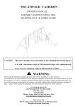
Read and gnderstand this manual before using machine.
1
3" THIGKilESS
.q.
STEEL CITY TOOL WORKS
vER.09.2014
-.
00.T2
,t,--,
401
r^
PLAI{ER with straisht Knife
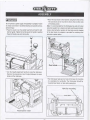
. Attach ihe dusl chute to the machine using two thumb
WARNIN
screws.
Do not connect to power supply until assembly is complete, Failure
The dust chute can be mounted to direct chips to either side
of thickness planer.
Io comply could result in accidental starting and possible serious
Note: lt is recommended that the thicknesser be used with a dust
personal injury.
extraction system for a cleaner and safer working environment.
.
Place the washer over the socket head bolt and feed the bolt
into the handle. Tighten ihe bolt to secure the handle in position.
Place the handle cap onto the handle.
Using a dust extraclion system will also help prevent clogging
of the dust chute. An adapter is provided for matching dust
extraction svstem better.
Dust chute
. Turn the height adjustment handle to raise the rollercase.
Remove the polystyrene insert located between the main
table and the rollercase.
. The thicknesser features four holes in the base for mounting
to a workbench or worktable. The lhicknesser should be
mounted level bench or table before ooeration.
Hole {or mounting
Polystyrene insert
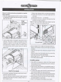
Observe the safety instructions and symbols on machine
before operation,
.
1. Raise or lower rollercase until it is just above the workpiece.
2. Posiiion the workpiece on the planer table below the
Rotate the height adjustment handle for raising or lowering
rolle rcase.
1"
the cutterhead,The depth scale shows the height of cutterhead
3. Rotate the knob until
is indicated.
4. The planer is now set to stop the rollercase when the
workpiece thickness reaches 1 "
above the main table.
Height
Note: To reset for a differeni depth stop, properly raise the
rollercase. Turn the knob to desired set-up.
adjustment
handle
tr a,ffiul
l-rta'
t*.fY
-\\.\\
tttt { }l /.ar
. A spring loaded depth-of-cut gauge is attached to front of
.[\
rollercase. The pointer on depth-of-cut gauge accurately
Pre-set knob
displays the depth-of-cut per pass when workpiece is
positioned below the gauge. Cranking ihe handle moves
the rollercase down and the poinier shows the desired
tr\\
t'
\\ tr e
\\ v Jl tt x.
rrn'r\#r-
.4f tut
rr
. Adjust the depth of cut to make an initiat tight (0.5mm) cut.
depth-o{-cut.
Switch on the machine and wait until the motor has reached
full soeed.
Press the board agalnst the infeed table and feed it into the
machine.
Release the board when the machine starts to cut and let the
board feed into the machine automatically.
Boards longer than 24" should have additional support from
free standing material stands.
Avoiding snipe
1. Snipe refers to a depression at either end of board caused
by an uneven force on cutterhead when work is entering or
G
Ieaving thickness planer.
2. Snipe will occur when boards are not supported properly or
when only one feed roller is in contact with work at beginning
or end of cut.
3. To avoid snipe, gently push the board up while feeding the
work until the outfeed roller staris advancing it.
Depth-of-cut gauge
. A six position workpiece thickness pre-set control knob
4. Move to the rear and receive planed board by genily pushing
it up when the infeed roller looses contact with the board
5. When planing more than one board of the same thickness,
is
mounted on right side of planer.
This knob allows to pre-set the desired finished workpiece
thickness that the planer will produce. Example: Plane a2"
thick workpiece up to 1"
butt boards together to avoid snipe.
6. Snipe is more apparent when deeper cuts are taken.
-8-
7-
WARNI
Turn off the machine and disconnect from the power supply before conducting maintenance work or settings.
To change the blades
lf the machine planes unevenly or tends to gouge, the blades must be changed.
To remove the blades, proceed as follows.
. Remove the dust chute.
'Loosen and remove four screws from blade guard on the rear side of thickness planer. Remove blade guard.
'Carefully turn cutlerhead by hand towards you until it is stopped by the self-engaging latch.
.
Loosen and remove six bolts from oib.
Gib bolts
.
Remove gib using magnets provided
CAUTION
Blade edges are extremely sharp. Keep fingers away from blades at all times.
'
Blade is located in position by two pins. Gently lift old blades from cutterhead using magnets. Do not make contact with
the blade
using f ingers. Use magnet only.
-9-
Brush inspection and replacement
WARNIN
Turn planer off and disconnect from power source. Brush life
depends on amount of load on moior. Regularly inspect brushes
after 50 hours of use. Brushes are located on either side of
planer motor.
.
.
.
.
Reverse or replace blade and carefully position it on the two
pins using magnets.
.
Replace gib and align the holes on the gib with holes on the
Loosen brush cap and carefully remove brush from motor.
Replace brushes if carbon is worn.
Replace brushes and tighten brush caps.
Brush cap
blade using magnets.
. Secure gib to Cutterhead using six bolts removed earlier.
.
Depress latch to release cutterhead. Release latch when
cutterhead can be turned by hand.
.
Turn cutterhead by hand until ii is stopped by self-engaging latch.
.
Reverse or re0lace blade as mentioned earlier.
Steel City Tool Works (USA)
4 Northpoint Court
Bolingbrook, lL 60440
For Customer Service-relate items Including Warranty, Parts, Service, Technical Questions:
1-877-724-8665
lf you are a Dealer or have a General Inquiry, Contact us directly.
For Product-relate calls, please use the Customer Service number above,
1 -888-304-8840
1-877-728-6651
Or you can reach us directly:
cuslomercare @ steelcitytoolworks, net
www. steelcitvtoolwo rks. com
-10
-
7-
Repair Parts lllustration for Tool Main Parts Assembly
1(4)
2(4)
,rd-.\.
3
^\i
/,/-@
d v\
i V t/'
\t'%,''
et.t
11
t
12
1
3(2)
14(4)
t3
22121
for
16
&'"
gg\
17(2)
1
8(2)
19
20
o1
22
24
./1
.1V
W\
u69
\
70)
@
r(o/.4
y +t(z)
\
@
64( )\
65(4)
66(4)
67(4)
68(4)
q4/t\
57(4)
46(2)
47(2)
4R( 2\
-
62(12L.-
63(12>"
4e(4)
5o(2)
51 (4)
52(2)
53(2)
58
6a(
t\
60(2)
61 (4)
-11-
-/1
_\ /"
vlc
--45
44
'/
Repair Parts List for Tool Main Parts Assembly
#
1
2
3
4
5
6
7
I
I
10
11
12
13
14
15
16
17
18
19
Parts No.
Description
40100-T2.001
M6-1.0 x 12mm Socket Pan Head
40100-T2-010
washer
LeftCap
2.5 x 28mm Coiter Pin
Roller
Handle Assembly
Up & Down Label
Right Cap
Hand Grips Label
Grip
40100-T2-011
M5-0.8 x 16mm Socket Head
40100-T2-012
Washer M5 x 15 x
40100-T2-002
40100-T2-003
40100-T2,004
2
40100-T2-005
40100-T2-006
40100-T2-007
40100-T2-008
40100-T2-009
40100-T2-013
40100-T2-014
40100-T2-015
40100-T2-016
40100-T2-017
40100-T2-018
40'100-T2-019
20 40100-T2-020
21 40100-T2-021
22 40100-T2-022
23 40100-T2-023
24 40100-T2-024
25 40100-T2-025
26 40100-T2-026
27 40100-12-027
28 40100-T2.028
29 40100-T2-029
30 40100-T2-030
31 40100-T2-031
32 40100-T2-032
33 40100-T2-033
34 40100-T2-034
35 40100-T2-035
36 40100-T2-036
37 40100-T2.037
38 40100-T2-038
39 40100,T2-039
Screw
6mm Flat
1
2
1
1
1
1
2
2
Bolt
1
1
Bolt
M5-0.8 x 8mm Set Screw
Elevaiing Nut (LH)
Elevating Nut (RH)
M20-l.0mm Hex Nut
M5-0.8 x 16mm Socket Head Bolt
Fixed Position Plate 1
Fixed Position Plate 2
M8-1.25mm Hex Nut
Fixed Position Bolt
Column
Elevating Screw (RH)
Elevating Screw (LH)
Guide(LH)
Table
M5-0.8 x 12mm Socket Head
M5-0.8 x 1Omm Hex Socket Cap
Screw
Guide(RH)
2
4
1
1
2
2
1
1
1
1
4
1
1
1
1
4
1
Bolt
1mm
GearSeat
Washer M8 x 16 x 0.5mm
Gear
Rapid Positioning Plaie
Rapid Positioning Shaft
M5-0.8 x 16mm Socket Head Bolt
Base
Ball
Washer M5 x 10 x
4
4
2mm
M5-0.8 x 12mm Socket Head
# Parts No,
40 40100-T2-040
41 40100-T2-041
42 40100-T2-042
43 40100-T2-043
44 40100:t2-044
45 40100-T2-045
46 40100-T2-046
47 40100-12-047
48 40100-T2,048
49 40100.T2-049
50 40100-T2-050
51 40100-T2-051
52 40100-T2-052
53 40100-T2,053
54 40100-T2.054
55 40100-T2-055
56 40100-T2-056
57 40100-T2-057
58 40100-T2-058
59 40100-T2-059
60 40100-T2-060
61 40100-T2-061
62 40100-T2-062
63 40100-T2-063
64 40100-T2-064
65 40100-T2-065
66 40100.T2-066
67 40100-T2-067
68 40100-T2-068
69 40100-T2-069
70 40100-T2.070
71 40100-T2-071
72 40100-T2-072
73 40100-T2-073
QTY.
1
1
1
1
1
1
1
2
1
1
-12-
Description
QTY,
Spring
Logo Label 1
2
Pre-Set0utlabel
Right Side Cover
Pre-Set Knob
M5-0.8 x 12mm Socket Head Bolt
Washer M13 x 26 x 2mm
2
600022 Ball Bearing
2
Bearing Reiainer
2
M5-0,8 x 10mm Hex Socket Cap Screw 4
Washer M10 x 18 x 1mm
2
Bevel Gear
4
Washer M4 x 15 x 2mm
2
M4-0.7 x 12mm Hex Socket Cap Screw 2
10mm LockWasher
4
10-1 x 40mm Socket Head Bolt
4
M6-1.0 x 20mm Hex Bolt
4
M6-1.0mm Hex Nut
4
Shaft
Support
2
Retaining Ring
2
M5-0.8 x 12mm Socket Head Bolt
4
M5-0.8 x 8mm Socket Head Bolt
12
Washer M5 x 10 x 1mm
12
Extension Table
2
M6-1.0 x 20mm Hex Bolt
4
1
1
1
1
I
M
.5
1
'10
Bushing
4
Wave Washer
4
Table Support
4
Nameplate Label
1
Warning Label
1
Left Side Cover
1
Magnet
1
4mm Hex Wrench
1
7-
Repair Parts lllustration for Rollercase Assembly Parts
\^
8e(3)
eo(2)
e1
(4)
92
,t-r')
s4
e5
96
ii
ii
s7(2)
83(2)
84(2)
85(2)
138
1
139
oo(4)
140
101(2)
1o2(2)
1
103
o4(3)
105
133
134(2)
1
35(2)
1
36(1 2)
137
1 1
e(2)
12o(4)
1
21
(2)
U
r
Repair Parts List for Rollercase Assembly Parts
Parts No.
74 40100-T2-074
75
76
Description
Replacement Knife Label
1
40100-T2-075
Caution Label
4
40100-T2-076
M5-0.8 x 1Omm Socket Head Bolt
4
Dust Chute
1
Thumb Screw
2
77 40100-T2-077
78 4010042-078
79 40100-T2-079
80 40100-T2-080
81 40100-T2-081
82 40100-T2-082
83 40100-T2-083
84 40100.T2-084
85 40100.T2,085
86 40100-T2-086
87 40100-T2.087
88 40100-T2.088
89 40100-T2-089
90 40100-T2-090
91 40100-T2-091
92 40100-T2-092
93 40100-T2-093
94 40100-T2-094
95 40100-T2-095
96 40100-T2-096
97 40100-T2.097
99 40100-T2-099
Dust Exhausl Port
1
Joint Port
1
Chute Plate
1
M4-1.4 x 8mm Flat Head Tap Screw
4
M5-0.8 x 8mm Pan Head Screw
2
WasherM5xl0xlmm
z
5mm Serrated Washer
z
M5-0.8 x 1Omm Pan Head Screw
1
Washer M5 x 10 x 1mm
1
Cord Clamp
1
Chain
Z
Sprocket
4
Spacer
1
M5-0.8 x 35mm Socket Head Bolt
A
Gearbox Assembly
I
Pinion
1
Cover
1
620372 Ball Bearing
z
Rollercase
M5-0,8 x 1Omm Hex Socket Cap Screw
4
101
40100-T2-101
M5-0.8 x 6mm Sei Screw
2
102
40100-T2-102
Retainer Plate
Z
103
40100-T2-103
Motor Rod
'|
104
40100-T2-104
M4-0.7 x 12mm Pan Head Screw
.t
105
40100-T2-105
Depth Indicator Assembly
1
106
40100-T2-106
M4-0.7 x 16mm Pan Head Screw
z
107
40100-T2-107
Depth Indicator
'I
108
40100-T2-108
Switch w/Key
1
109
40100-T2-109
Circuit Breaker
1
110
40100-T2-110
Motor Assembly
1
40100-T2-1
Logo Label 2
1
Brush Cap
z.
Brush (Set of 2)
1
112
11
40100-T2-112
113 40100-T2-113
Parts No.
40100-T2-114
40100-T2-115
116 40100-T2-116
117 40100-T2-117
118 40100-T2-118
119 40100.T2-119
120 40100-T2-120
121 40100-12-121
122 40100-T2-122
123 40100-T2-123
124 40100-T2-124
125 40100f2-125
126 40100-T2-126
127 40100-T2-127
128 40100-T2-128
129 40100-12-129
130 40100-T2-130
131 40100-T2-131
132 40100-T2-132
133 40100.T2-133
134 40100.T2-134
135 40100-T2-135
136 40100-T2-136
137 40100-T2-137
138 40100.T2-138
139 40100-T2-139
140 40'100-T2-140
141 40100-T2.141
142 40100-T2-142
143 40100-T2-143
I
40100-T2-100
11
114
115
15 Retaining Ring
100
1
#
QTY.
1M 40100-T2-144
Description
QTY.
Holder
2
M5-0.8 x 8mm Set Screw
2
Spacer
Washer M8 x 16 x 2mm
M8-1.25 x 20mm Hex Head Bolt
LH Spring
2
Bearing Block
4
LH Retainer
2
M5-0.8 x 12mm Socket Head Bolt
I
lnfeed Roller
Outfeed Roller
RH Spring
2
RH Retainer
2
,Smm Hex Nut(LH)
Motor Pulley
Cutterhead Pulley
Belt
Bearing Seat
M5-0.8 x 12mm Socket Head Bolt
3
Cutterhead
Blade
2
Blade Locking Bar
2
Locking Bolt
12
M5x5x12mmKey
Cutterhead Lock
Spacer
M5-0.8 x 12mm Socket Head Bolt
M5-0.8 x 1Omm Hex Sockei Cap Screw 2
Belt Guard
Plunger
Spring
Operato/s Manual
Brush
1
1
1
1
1
M 16-1
1
1
'l
1
1
1
1
1
1
1
1
1
1
1
- 1A
t+-
--T-
new Steel Citv
your
purchasing
THANKYOU tor
and
tested'
designed'
has been
Planer. This planer
inspectedwithyou'thecustomer'inmind'Whenproperly
usedandmaintained,yourplanerwillprovideyouwith
yearsoftroublefreeservice,whichiswhyitisbacked
byoneofthelongestmachineryWarrantiesinthebusiness'
ThisplanerisiustoneofmanyproductsintheSteelCity,s
familyofwoodworkingmachineryandisproofofour
customer satisfaction'
total
to
commitment
AtSteelCitywecontinuetostriveforexcellenceeach
andeverydayandvaluetheopinionofyou,ourcustomer.
,lza Fl'tltl
ForcommentsaboutyourplanerorSteelCityToolWorks,
ou, *"n site at www.steercitytoolworks'com'
il'",rn
I
-
INTRODUCTION
sEcTtoN
1
sEcTtoN 2
3
SECTION 4
SECTION 5
SECTION 6
SECTION 7
SECTION
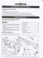
Table of Contents
lntroduction
Product Specifications
Safety lnstructions
1-4
Electrical Requirements
Accessories and Attachments
..,.,.........
................6
Carton Contents
I
Assembly
SECTION 9
Operation
sEcTtoN
10
Maintenance
SECTION
11
Contact Us
sEcTtoN
12
Repair Parts lllustration & List
sEcTtoN
..0
9-1 0
10
This user manual is intended for use by anyone working with this machine, lt should be kept available
for immediate reference so that all operations can be performed with maximum efficiency and safety,
Do not attempt to perform maintenance or operate this machine until you have read and understand the
information contained in this manual,
The drawings, illustrations, photographs, and specifications in this user manual represent your machine
at time of print, However, changes may be made to your machine or this-manual at any time with no
obligation to Steel City Tool Works.
-0-
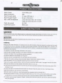
Motor Power
Motor Protection
Pass-through width
Pass-through height
Max. width acceptance
Feed rate speed
Cutterhead speed
115V 60Hz 15A
YES
13 inch (330 mm )
6 inch (I52 mm)
L/32 inch (0.8 mm) W>6inch
7/64 inch (2.8 mm) W<6inch
26 FPM
9500 rpm
WARNI
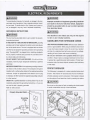
When using electric tools, basic safety precautions, including the following, should always be followed to reduce
the risk of fire,
electric shock and personal injury. Read all these instructions before operating this product and save the instructions.
CAUTION
Read and follow all Safety Rules and operating Instructions before First Use of this product.
Keep this manual with tool.
GENERAL
Please pass this safety information on to all persons who work with the machine. People who operate this
machine must have read
the instructions for use and, in particular, the chapter concerning safety information. Once they have begun work, it
is too late. This
is especially the case for personnel who only occasionally use the machine, for example when the machine is
to be equipped
or
maintenance work carried out.
.
Pay attention to all safety and danger information on the machine.
'Keep allsafety and danger information on the machine completely and in a legible condition.
. Check the line cables. Do not use defective electrical connections.
.
See that the machine is firmly situated on a firm ground
Make sure that there is adequate light in the work place and near the machine
' Take care when working, rotating cutting tools preseni danger of bodily harm to fingers and hands.
. when the machine is in use, all protective equipment and covers must
be mounted.
'
'Keep all other people, especially children, away from the work area and the machine when it is plugged in as wellas its cables.
.
'
Make sure that children do not have access to the machine when it is not in use.
Do not overtax the equipment and use it only within the performance parameters described in the technical
data section of the
information for use.
'
.
Do not use the cable for uses other than that for which it is intended. Protect the cables from heat,
oil and shar0 corners.
Keep the hand holds dry, clean and free of oil and grease.
'Before the machine is switched on, check that keys and other preparatory iools are removed from it.
'
Be alert and pay attention to what you are doing. Be sensible about your work. Do not use this machine
when you are not able
t0 concentrate. Do not use this machine when you are tired or under the influence of alcohol, drugs or medications.
'The operator must be at least
if they are supervised.
18 years old. People in training must be at least 16 years old, and may only operaie the machine
--:-:T
. People operating the machine should not be distracted.
. KeeP the service area in good order; remove wood shavings. A disorderly work
. Protect the machine f rom rain and dampness.
. Do not operate the machine in a damp or wet environment,
area can lead to accidents.
. Store the machine in a safe place, so that nobody can be injured by the machine or inadvertently switch it on. Do not let the
machine stand without protection outdoors or in a damp environment.
. Only operate the machine according to the appropriate
uses.
. Do not operate the machine where there is danger of fire or explosion.
. When using this piece of equipment, avoid physical contact with grounded items (for example pipes, radiators, electrical stoves,
ref
rigerators).
. Wear close fitting cloths. Remove jewelry, rings and watches.
. When operating the machine wear hearing prolection, proiective glasses as well as a dust protection
. Wear a cap or hair net to protect long hair.
mask.
. The safety equipment on this machine may not be removed or made useless. Carry oui changes, adjustments, measurement or
cleaning work only when the motor is turned off. Unplug the machine and wait until all rotating tools have come to a standstill.
.Installation, repairs, and maintenance work on the electrical equipment may only be carried out by a specialist.
. Allprotective and safety devices must be immediately reinstalled after repair or maintenance work has been carried out. In order
to dealwith problems, turn the machine off. Pullout the plug!
.
Use an exhaust extraction sysiem to remove wood chips or sawdust. The current speed at the vacuum heads must be 20 m/s.
. When the machine is moved, even a small distance, it must be disconnected from the electrical current. Before starting the
machine up again it must be connected to the electricalsupply in an orderly way.
. The operator must iurn off the motor when he leaves the workplace. Pull out the plug! Unplug the machine when it is not
needed.
. Check the machine each time it is started up to make sure that the protective equipment and the switches are in order. Do not
use the machine if the protective equipment, the switch, the electrical connections, the plug or other parts of the machine are
damaged.
. The machine should be anchored into the ground by means of screws when it is in operation,
. The machine must be grounded. The yellow/green (green) wire is the ground wire.
. The machine could be used only if it is connected to the effective chip and dust extraction system.
. That the dust extraction equipment is to be on before commencing machining.
Special safety instructions for thicknesser
.
Do not use dull cutting blades since this increases the danger of kickbacks.
. When short pieces of wood are to be planed, use a push stick to position the work pieces.
.
.
.
.
.
Do not use the machine to notch or harrow wood.
Regularly check thai the cutting block are working properly.
Use only well sharpened cutting blades in order to work better and more safely,
Do not use cracked cutting blades, or those which are no longer in their originalform.
Use suitable aides to support heavy or bulky pieces when they are to be thciknessed. Such aides include the extra units: jack up
and universal trucks.
. Check regularly that the cutting blade are securely fastened.
. When changing the cutting blade, wear appropriate work gloves.
. When working on the thicknesser, do not wear work gloves; safe in those cases when the work piece is rough.
-2-
T
Appropriate Use
' Before beginning work, all protective and safety equipment
must be mounted on the machrne.
. The machine is conceived to be operated by one person.
.
Pay attention to all safety and danger warnings on the machine.
. All safety and danger warnings on the machine must be kept legible.
: Should larger work pieces
be handled, such that the table top must be tipped, a table extension or a jack up truck (extra accessory)
must be used.
'
'
lf the machine is used in an enclosed space, then an exhaust extraction system must be hooked up to it.
Use the mmhine only when it is in technically perfect condition and only for appropriate jobs, with an awareness of safety and
possible dangers, based on observation of the operating instructions! In particular, problems which could influence the safetv
of use must be immediately dealt with!
' All of the manufacturer's safety, work, and maintenance regulations as well as the given norms in the Technical Data must be observed.
' The appropriate accident prevention rules and all those generally recognized safety rules must be observed.
' The machine may only be used, maintained or repaired by those persons who understand and have been instructed in the potential
dangers' Independent changes in the machine cancel any manufacture/s liability for any damages that result f rom these cnanges,
'The machine may only be used wiih the manufacturer's original parts and tools.
'
Note: the use of tools or equipment other than those specif ied in the operating instructions can mean danger for the user,
'Any use beyond what is specified here is not appropriaie. The manufacturer is not liable for any damages which result from
inappropriate use; the entire risk is carried by the user.
.
Do not lean too far forward.
. Always stand firmly on the ground and maintain your balance
'Always concentrate on your work. Do not work with the machine when you are tired or under the influence of drugs or alcohol.
'
Check ihe machine for damaged parts. lf protective equipment or any other part is damaged, check caref ully before you continue
your work whether it functions properly. Test the release of moveable parts and make sure they can move freely. Be
certain ihat
there are no breaks, cracks or other conditions that could negatively influence the functioning of the machine. Damaged protective
equipment or other parts that are defective must be repaired or replaced by a recognized customer service center unless otherwise
specified in the operating instructions.
'
Have defective switches replaced by a recognized customer service center. Do not work with the machine if the ON/0FF switch
or the speed of rotations cannot be moved properly.
'Make sure that the electrical current corresponds to the requirements of the type labelon the machine.
. Treat your tools with care: they can be extremely sharp.
'Before starting work with the machine, make sure that objects such as nails and screws have been removed from the work
.
piece.
Keep your hands away f rom rotating tools.
. When turning on the machine, the tools may nol touch the work piece.
'Once you have turned on the machine, let it run for a while before you make the first cui. Pay aitention to any vibrations or
drumming which might indicate an improperly mounted tool.
' Pay attention to the rotational direction of the tool and the correct entry direction of the work prece.
' Do not leave ihe running machine unattended.
not touch the tool after the work has been completed. lt can be extremely hot and can burn the skin.
'Rags, cables and similar items should not be left on the work surface when the machine is in operation.
'Do
After the machine has been in operation for a long period of time, external metal parts and equipment can get hot.
'Turn the machine off and wait uniilthe tool has come to a complete stop before removing the work piece from the table
. Support the work piece properly.
'
'Use extra aides, such as horizontal holders, for working
. Do not let the machine stand in the rain.
on smaller work pieces.
-J-
7
WARNI
The use of any equipment or external parts that is not recommended in this operating instruction
can lead to
bodily harm.
This product may only be used for the purposes for which it was made. Any other use which is not
described
in these operating instructions is understood to be inappropriate. The operator, and not the manufacturer,
is
responsible for all damages or injuries which result from improper use.
Remaining hazards
The machille has been manufactured according to technical standards and recognized safety rules.
Still, when
working with the machinen certain residual risks can come about.
'There can be danger or injury lo fingers and hands due to rotating tools when the work piece is led into the machine in an
inappropriate manner,
'Wood dust or saw dust can present danger to health. li is imperative that the operator wear personal protection devices such
as goggles. Use an exhaust extraction system!
'
Danger of injury due to defective tools. Check regularly that the tools are in good working order.
'Danger of injury to fingers and hands when changing the tools. Use appropriate work gloves.
'
'
Danger of injury when the machine is being turned on due to rotating tools.
Danger due to the electrical current when the electrical connections are not properly installed,
'Danger to the operaior's health due to lhe rotating tools if the operator has long hair and loose clothing. personal protection
devices such as hair nets and close-fitting clothing should be worn.
'In spiie of all safeiy measures being followed there can stillbe obvious residual risks.
. Residual risks can be reduced when all the instructions in general are followed.
r
AWARNIN
AWARNIN
To avoid electrical hazards, fire hazards, or damage to the tool,
lmproper connection of equipment grounding conductor
use proper circuit protection. Use a separate electrical circuit
can result in the risk of electrical shock, Equipment
should be grounded while in use to protect operator
from electrical shock.
for your tools. To avoid shock or fire, if power cord is worn or
cut, or damaged in any way, have it replaced immediately.
GROUNDING INSTRUCTIONS
WARNIN
WARNIN
This machine is for indoor use only. Do not expose
to rain or use in damp locations.
This iool must be grounded while in use to protect the operator
from electrical shock.
GUIDELINES FOR EXTENSION CORDS
lN THE EVENT 0F A MALFUNCTION
0R BREAKDOWN, groundrng
USE PROPER EXTENSION CORD. Make sure your extension
provides a path of least resistance for electric current and reduces
cord is in good condition. When using an extension cord, be sure
ihe risk of electric shock. This tool is equipped with an electric
to use one heavy enough to carry the current your product
cord that has an equipment-grounding conductor and a grounding
will draw. An undersized cord will cause a drop in line voltage,
plug. The plug MUST be plugged into a matching receptacle
resulting in loss of power and cause overheating.
that is properly installed and grounded in accordance wiih
Be sure your extension cord is properly wired and in good
ALL local codes and ordinances.
condition. Always replace a damaged exlension cord or have
D0 N0T M0DIFY THE PLUG PROVIDED. lf it will not fit the
it repaired by a qualified person before using it. Protect your
receptacle, have the proper receptacle installed by a qualified
extension cords from sharp objects, excessive heat and damp
electrician.
or wet areas.
IMPROPER CONNECTION of the equipment-grounding conductor
can result in risk of electric shock. The conductor with green
CIRCUIT BREAKER
insulation (with or without yellow stripes) is the equipment-grounding
The thicknesser is equipped with a motor protection device-circuit
conductor. lf repair or replacement of the electric cord or plug
breaker, The breaker will automatically shut the thicknesser
D0 NOT connect the equipment-grounding conductor
off when excessive current is consumed. lf the breaker is tripped,
is necessary,
to a live terminal.
turn the planer off and resei the circuit by pressing the button.
CHECK with a qualified electrician or service person if you do not
Acnunoru
completely understand the grounding instructions, or if you are
not sure the tool is properly grounded.
Be sure to turn the planer off prior to resetting the circuit breaker
Refer to nether picture:
to avoid unintentional start-up of the thicknesser.
Circuit
Properly Grounded Outlet
Breaker
Grounding
3-Prong
-5-
-_='7-
RECOMMENDED ACCESSORIES
To avoid injury:
.
Use only accessories recommended for this machine.
' Follow instructions ihat accompany accessories. Use of improper accessories may cause hazards.
' Use only accessories designed for this machine to avoid injury f rom thrown broken parts or workpieces.
' Do not use any accessory unless you have completely read the instruction or operator's manual for that accessorv.
UNPACKING AND CHECKING CONTENTS
Carefully unpack the machine and all its parts.
WARNIN
.
To avoid injury from unexpected starting, do not plug the power
cord into a power source receptacle during unpacking and
assembly.
This cord must remain unplugged whenever you are assembling
or adjusting the machine.
r lf any part is missing or damaged, do not plug the machine
until the missing or damaged part is replaced, and assembly
is complete.
TABLE OF LOOSE PARTS
Unpack carton; check you machine to see parts listed below:
A
E
\\
I[
\
IL
Ij---t
rE
ttr
/\
t:
\
1\
6E \Y
'g