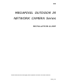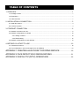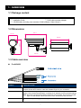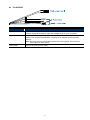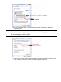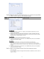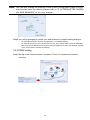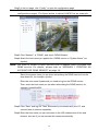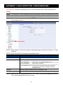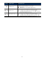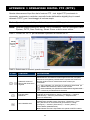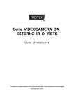
1
Powerful Remote Surveillance
Distance makes no difference
To Our Valuable Customers,
Thank you for choosing this product. You’ll be amazed by those useful
functions this product provides, especially for the powerful mobile
surveillance support.
Remote access via different platforms is widely supported:
a) For mobile platforms, iPhone®, BlackBerry®,
Nokia® Symbian®, Windows® Mobile & Android™
are available with our self-developed and free
program, EagleEyes, installed.
EagleEyes
b) For web browsers, Internet Explorer®, Mozilla®
Firefox®, Safari® and Google Chrome™ are
supported.
c) Apple’s media player, QuickTime®, is also one tool
you can use.
To monitor and control multiple network devices, you can also install our
free CMS software provided within the CD manual.
To know more about our mobile phone program, “EagleEyes”, and where to
download, please visit:
http://www.eagleeyescctv.com
To know more about feature applications, please visit:
www.eagleeyescctv.com/video
To seek for technical support, please contact:
[email protected]
To give us your precious suggestions and comments, please contact:
[email protected]
364Z
MEGAPIXEL OUTDOOR IR
NETWORK CAMERA Series
INSTALLATION GUIDE
Please read instructions thoroughly before operation and retain it for future reference.
N36x_V1.0
IMPORTANT SAFEGUARD
All lead-free products offered by the company comply with the requirements of the European
law on the Restriction of Hazardous Substances (RoHS) directive, which means our
manufacture processes and products are strictly “lead-free” and without the hazardous
substances cited in the directive.
The crossed-out wheeled bin mark symbolizes that within the European Union the product
must be collected separately at the product end-of-life. This applies to your product and any
peripherals marked with this symbol. Do not dispose of these products as unsorted municipal
waste. Contact your local dealer for procedures for recycling this equipment.
Trademark Acknowledgements
Microsoft & Internet Explorer mentioned in this document are the registered trademarks of their
respective holders.
Disclaimer
We reserves the right to revise or remove any content in this manual at any time. We do not warrant or assume
any legal liability or responsibility for the accuracy, completeness, or usefulness of this manual. The content of
this manual is subject to change without notice.
MPEG4 Licensing
THIS PRODUCT IS LICENSED UNDER THE MPEG4 VISUAL PATENT PORTFOLIO LICENSE FOR THE
PERSONAL AND NON-COMMERCIAL USE OF A CONSUMER FOR (i) ENCODING VIDEO IN COMPLIANCE
WITH THE MPEG4 VISUAL STANDARD (“MPEG-4 VIDEO”) AND/OR (ii) DECODING MPEG4 VIDEO THAT
WAS ENCODED BY A CONSUMER ENGAGED IN A PERSONAL AND NON-COMMERCIAL ACTIVITY
AND/OR WAS OBTAINED FROM A VIDEO PROVIDER LICENSED BY MPEG LA TO PROVIDE MPEG4
VIDEO. NO LICENSE IS GRANTED OR SHALL BE IMPLIED FOR ANY OTHER USE. ADDITIONAL
INFORMATION INCLUDING THAT RELATING TO PROMOTIONAL INTERNAL AND COMMERCIAL USES
AND LICENSING MAY BE OBTAINED FROM MPEG LA, LLC. SEE HTTP://WWW.MPEGLA.COM.
GPL Licensing
This product contains codes which are developed by Third-Party-Companies and
which are subject to the GNU General Public License (“GPL”) or the GNU Lesser
Public License (“LGPL”).
The GPL Code used in this product is released without warranty and is subject to the
copyright of the corresponding author.
Further source codes which are subject to the GPL-licenses are available upon
request.
We are pleased to provide our modifications to the Linux Kernel, as well as a few new
commands, and some tools to get you into the code. The codes are provided on
the FTP site, and please download them from the following site or you can refer to
your distributor:
ftp://ftp.dvrtw.com.tw/GPL/AV074/
TABLE OF CONTENTS
1. OVERVIEW..............................................................................................................................1
1.1 Package content ........................................................................................................................................... 1
1.2 Dimensions ................................................................................................................................................... 1
1.3 Cable overview ............................................................................................................................................. 1
2. INSTALLATION & CONNECTION ...........................................................................................3
2.1 Install the camera.......................................................................................................................................... 3
2.2 Connect to power.......................................................................................................................................... 4
3. ETHERNET CONNECTION.....................................................................................................6
3.1 Network connection via LAN......................................................................................................................... 6
3.2 Network configurations via wizard .............................................................................................................. 10
3.2.1 Setting in wizard.............................................................................................................................. 10
3.2.2 DDNS setting .................................................................................................................................. 12
3.3 Network configurations via web browser .................................................................................................... 14
4. BEFORE YOU START TO USE .............................................................................................16
4.1 Camera environment .................................................................................................................................. 16
4.2 Focus calibration in each focal length (Only for AVN363) .......................................................................... 16
APPENDIX 1 CREATING AN ACCOUNT FOR DDNS SERVICE ..........................18
APPENDIX 2 FACE DETECTION CONFIGURATIONS ............................................21
APPENDIX 3 DIGITAL PTZ (DPTZ) OPERATIONS ...................................................22
1. OVERVIEW
1.1 Package content
□ Network camera
□ Installation Sticker
□ Installation Guide
□ RJ45 cable extender adapter
□ CD-ROM disc (including user manuals & CMS software “Video Viewer”)
1.2 Dimensions
282.4
117.89
212.63
246.87
236.03
1.3 Cable overview
For AVN363
CABLE
DESCRIPTION
RJ45 network cable
Connect it to the supplied RJ45 cable extender adapter for cable extension, and
prepare another RJ45 network cable with suitable length for your connection.
Reset wires
Remove the insulating coating of these two wires, and twist them together to reset
default. This will reset all parameters, including the IP address to factory default settings.
Note: Disconnect power before twisting these two wires together, and connect to power
again for reset default. When the reset is done, disconnect these two wires.
Power wires
Connect to AC power supply. For details, please refer to “2.2 Connect to power” at page
4.
1
For AVN362
CABLE
DESCRIPTION
RJ45 network cable
Connect it to the supplied RJ45 cable extender adapter for cable extension, and
prepare another RJ45 network cable with suitable length for your connection.
Reset wires
Remove the insulating coating of these two wires, and twist them together to reset
default. This will reset all parameters, including the IP address to factory default
settings.
Note: Disconnect power before twisting these two wires together, and connect to
power again for reset default.
Power cable
Connect to DC12V power supply.
2
2. INSTALLATION & CONNECTION
2.1 Install the camera
Note: The illustration below is for installation only, and the actual product may look
different from the illustration below.
3
2.2 Connect to power
For AVN363
Get a power cord and cut off its female connector side. Then, remove the insulating
coating to reveal positive, negative and ground wires.
Find the two wires labeled “L” (red) & “N” (black) on your camera, and remove a small
piece of their insulating coating to reveal the naked wires.
4
Twist the camera’s and power cord’s wires together according to the corresponding
electrodes (positive to positive, negative to negative, disregarding the ground wire).
Then, use the insulation tape to cover the connected wires.
For AVN362
Connect the power adapter (optional) to the camera’s power connector and power
outlet.
Note: The regulated power adapter is DC12V / 1.5A to operate this device.
5
3. ETHERNET CONNECTION
Before using this network camera, please follow the instructions below to finish the
network connection settings based on your installation environment:
To configure the network settings, you must connect the camera to your PC by LAN.
For details, please refer to “3.1 Network Connection via LAN” at page 6.
To configure the network settings via the setting wizard, please refer to “3.2
Network Configurations via Wizard” at page 10.
To configure the network settings via a web browser, please refer to “3.3 Network
configurations via web browser” at page 14.
3.1 Network connection via LAN
Step1: Connect this network camera and your PC via a RJ45 network cable, and make
sure the camera is powered on.
Step2: Set the PC’s IP address as “192.168.1.XXX” (1~255, except 10).
For Windows 2000 users:
a) Select “Start” “Settings” “Network and Dial-up Connections”.
b) Right-click on “Local Area Connection”, and select “Properties”.
c) In the “General” tab, select “Internet Protocol (TCP/IP)”, and select “Properties”.
6
d) In the “General” tab, select “Use the following IP address”, and set the IP address as
described below.
Note: It’s recommended to note down the current settings first and then change
as instructed. It’s helpful when you need to restore the PC network settings
for connecting to Internet later.
e) Click “OK” to close the “Internet Protocol (TCP/IP) Properties” dialog box. Then, click “Close”
to close the “Local Area Connection Properties” dialog box.
For Windows XP users:
a) Select “start” “Control Panel” “Network and Internet Connections” “Network
Connections” (If you’re in “Category View”).
7
b) In “LAN or High-Speed Internet”, right-click on “Local Area Connection”, and select
“Properties”.
c) In the “General” tab, select “Internet Protocol (TCP/IP)”, and select “Properties”.
d) In the “General” tab, select “Use the following IP address”, and set the IP address to
“192.168.1.XXX” (XXX can be any value from 1~255 except 10).
Note: It’s recommended to note down the current settings first and then change
as instructed. It’s helpful when you need to restore the PC network settings
for connecting to Internet later.
e) Click “OK” to close the “Internet Protocol (TCP/IP) Properties” dialog box. Then, click “Close”
to close the “Local Area Connection Properties” dialog box.
For Windows Vista users:
a) Select “ ” (start) “Control Panel” “Network and Internet” to enter the “Network and
Sharing Center”. Then, click “Manage network connections” (If you’re in “Category View”).
b) Right-click on “Local Area Connection”, and select “Properties”.
c) In the “Networking” tab, select “Internet Protocol Version 4 (TCP/IPv4)”, and select
“Properties”.
8
d) In the “General” tab, select “Use the following IP address”, and set the IP address as
described below.
Note: It’s recommended to note down the current settings first and then change
as instructed. It’s helpful when you need to restore the PC network settings
for connecting to Internet later.
e) Click “OK” to close the “Internet Protocol Version 4 (TCP/IPv4) Properties” dialog box. Then,
click “Close” to close the “Local Area Connection Properties” dialog box.
9
3.2 Network configurations via wizard
A quick installation wizard is available via your web browser for password change, date &
time settings, and network configurations.
For details about the wizard, please refer to “3.2.1 Setting in Wizard” at page 10.
For details about DDNS setting for PPPoE and DHCP, please refer to “3.2.2 DDNS
Setting” at page 12.
Note: You can also change the settings in the system configuration page via your
web browser later. For details, please refer to “3.3 Network configurations
via web browser” at 14.
3.2.1 Setting in wizard
Step1: Open your web browser, for example, Microsoft Internet Explorer, and enter
“http://192.168.1.10” in the URL address box.
Step2: In the login page, key in the default user name (admin) and password (admin),
and enter the security code from the image below if any. Then, click “LOGIN”.
Step3: The wizard is then starting analyzing your network environment, and shows your
network environment. Select “Next” to continue.
Step4: In “Account”, change the access password if needed.
If not, leave all the columns blank, and select “Next”.
Step5: In “Date and Time”, check if the date and time setting are correct and modify if
necessary.
10
Step6: In “Network”, select the network type based on your network environment (Static
IP / PPPoE / DHCP), and key in the information needed.
Note: This camera doesn’t support POE router or hub.
For Static IP:
a) Enter the information of “Server IP”, “Gateway” and “Net Mask” obtained from your ISP
(Internet Service Provider).
b) Enter the port number. The valid number ranges from 1 to 9999. The default value is 80.
Typically, the TCP port used by HTTP is 80. However in some cases, it is better to change
this port number for added flexibility or security.
For PPPOE:
a) Enter the user name and password obtained from your ISP.
b) Continue the DDNS setting as instructed in “3.2.2 DDNS Setting” when you’re prompted to
restart the web browser in Step8.
For DHCP:
a) Before selecting this option, you need to finish the DHCP router settings first.
Get a router and connect it to the Internet via your PC (with Static IP or PPPoE setting).
There are different setting methods for different routers. Please refer to their respective user
manuals.
b) Continue the DDNS setting as instructed in “3.2.2 DDNS Setting” when you’re prompted to
restart the web browser in Step8.
Step7: In “Apply”, all the changes are listed. Check if the changes are correct.
‧ If yes, click “Save”.
‧ If no, click “Back” to where the changes should be made for modification, and click “Save” to
apply the settings.
11
Note: You can also change the settings in the system configuration page via your
web browser later. For details, please refer to “5. ACCESSING THE CAMERA
VIA WEB BROWSER” in the user manual.
Step8: You will be prompted to restart your web browser for network setting changes.
‧ For PPPoE and DHCP, continue as instructed in “3.2.2 DDNS Setting”.
‧ For Static IP, disconnect your camera and your PC, and connect them to Internet separately.
Next, enter the IP address of the camera in the URL address box of the web browser, and see
if you can access the camera successfully.
3.2.2 DDNS setting
Step1: Re-log in the network camera, and select “Close” for network environment
checking.
12
Step2: In the live page, click “Config.” to open the configuration page.
Note: Different camera models might have different live view control and
configuration pages. The figure below is taking AVN363 as an example.
Step3: Click “Network”
“DDNS”, and check “DDNS Enable”.
Step4: Select the host name you applied for a DDNS service in “System Name” (ex.
dyndns).
Note: You need to create a DDNS account from a website which provides free
DDNS service. For details, please refer to “APPENDIX 1 CREATING AN
ACCOUNT FOR DDNS SERVICE” at page 18.
Select the system name you set when subscribing the DDNS service from the
drop-down list, for example, dyndns.
Enter the user name & password you used to log into the DDNS service.
Then, enter the host name you set when subscribing the DDNS service, for
example, headoffice523.
Step5: Click “Save” and log out. Then, disconnect your camera and your PC, and
connect them to Internet separately.
Step6: Enter the host name you just note down in the URL address box of the web
browser, and see if you can access the camera successfully.
13
3.3 Network configurations via web browser
Step1: Open your web browser, for example, Microsoft Internet Explorer, and enter
“http://192.168.1.10” in the URL address box.
Step2: In the login page, key in the default user name (admin) and password (admin),
and enter the security code from the image below if any. Then, click “LOGIN”.
Note: Skip the wizard if any.
Step3: In the live page, click “Config.” to open the configuration page.
Note: Different camera models might have different live view control and
configuration pages. The figure below is taking AVN363 as an example.
Step4: Click “Network” “Network” to select the connection type: Static IP / PPPoE /
DHCP.
Note: This camera doesn’t support POE router or hub.
For Static IP:
a) Enter the information of “Server IP”, “Gateway” and “Net Mask” obtained from your ISP
(Internet Service Provider).
b) Enter the port number. The valid number ranges from 1 to 9999. The default value is 80.
Typically, the TCP port used by HTTP is 80. However in some cases, it is better to change
this port number for added flexibility or security.
c) Click “Save” to save your network configurations, and logout.
d) Disconnect your camera and your PC, and connect them to Internet separately. Then, enter
14
the IP address or host name you just note down in the URL address box of the web browser,
and see if you can access the camera successfully.
For PPPOE:
a) Enter the user name and password obtained from your ISP, and click “Save”.
b) Continue the DDNS setting as instructed in “3.2.2 DDNS Setting”.
For DHCP:
a) Before selecting this option, you need to finish the DHCP router settings first.
Get a router and connect it to the Internet via your PC (with Static IP or PPPoE setting).
There are different setting methods for different routers. Please refer to their respective user
manuals.
b) Continue the DDNS setting as instructed in “3.2.2 DDNS Setting”.
15
4. BEFORE YOU START TO USE
After you finish camera installation and network configurations, some camera
configurations in “Config.” are required to complete for the camera to work properly.
Please follow the instructions below.
4.1 Camera environment
Select “Camera” to enter the “Camera Configuration” page, and select “Indoor” or
“Outdoor” according to your installation environment.
This helps to automatically adjust the camera itself to produce the images suitable for
the selected environment.
4.2 Focus calibration in each focal length (Only for AVN363)
AVN363 is a vari-focal IR network camera with f4.0 ~ f9.0. To ensure the image
clearness and sharpness, go to “Calibration” to adjust the focus in each focal length
after the camera is installed.
When you finish the calibration, select “Storage” to save, or “Back to Default” to discard.
16
Icon
Function
Description
Auto Calibration
Click to start calibrating the focus in each zoom ratio.
Manual Calibration
/
/
Zoom in / out
Click
Focus in / out
Click
/
/
17
to select the zoom ratio you want to adjust.
to adjust the focus for the selected zoom ratio.
APPENDIX 1 CREATING AN ACCOUNT FOR DDNS SERVICE
For PPPOE or DHCP, you should enter the host name which points to the IP address of your
network camera for login first. Besides using the default DDNS service, you can also apply
for new DNS services.
There are many websites for free DDNS service application, and below shows an example of
DDNS account application from the website http://www.dyndns.com.
Step1: Go to http://www.dyndns.com, and click “Create Account” to sign up a DDNS account.
Step2: Enter all the information necessary for signing up an account according to the website
instructions.
‧Key in a user name for login, for example, headoffice523.
‧Set the password and input it again to confirm.
‧Key in your E-mail address and input it again to confirm.
Then, click “Create Account”.
Step3: The system will automatically send a confirmation email to your email account.
Please read this email within 48 hours and complete the procedure to activate your
18
account according to the instructions in the email.
When the account is confirmed, you will see “Account Confirmed”. Your account is
created successfully now.
Step4: Click “login”, and enter the user name and password you preset before to log in.
Step5: Click “Add Host Services”.
‧Input a meaningful host name.
‧Choose a host system name.
‧Enter the IP address you want to redirect.
Note down the whole host name, for example, headoffice523.dyndns.org. Then, click
“Add To Cart” for billing.
Note: This service is free. Just finish the billing process, and NO paying
information is required.
Step6: Click “Activate Services” after checkout, and you’re ready to use DDNS services now.
19
Step7: Return to your web browser, and go to “Network” “DDNS”. Follow the description in
“3.2.2 DDNS setting” at page 12.
20
APPENDIX 2 FACE DETECTION CONFIGURATIONS
Face detection is used to especially zoom in on the intruder’s face, easy for everyone to
identify.
Note: This function is not available when the stream format is selected as MJPEG.
Note: When this function is enabled, DPTZ, Smart Zoom, and optical zoom are
not allowed to use.
STEP1: Click “Config.” to enter the system configuration page, and select “Camera”
Tracking”.
STEP2: Select and set Face Tracking as described below:
ITEM
DESCRIPTION
Face Detection
Select “Enable” to activate or “Disable” to deactivate this function.
OSD
Select “ON” to display the following status messages on the live view:
FACE STANDBY:
This function is activated and ready to use.
FACE TRACKING:
This function is tracking.
“Face
FACE ZOOM IN / OUT: This function is zooming on the face for tracking /
zooming out when the tracking object leaves the
surveillance area.
Sensitivity
Set the tracking sensitivity from HIGH / MEDIUM / LOW.
Resolution
Set the resolution for face tracking from Auto / VGA / QVGA.
STEP3: When all the configurations are done, click “Save” to save your changes, and click
“Live” on the top to return to the live view.
21
APPENDIX 3 DIGITAL PTZ (DPTZ) OPERATIONS
This fixed network camera type has PTZ capability, i.e. digital PTZ (hereafter called “DPTZ”),
for wide area monitoring.
Note: When this function is enabled, Face Tracking, Smart Zoom, and optical
zoom are not allowed to use.
STEP1: Click “DPTZ” to show the DPTZ control panel.
STEP2: Select the functions when needed:
ICON
/
FUNCTION
Fit to screen /
Restore to original size
Take snapshots
DESCRIPTION
There are several monitor resolutions available. When the selected
resolution is out of your current live view support, a part of your
surveillance area might get covered on the screen, and you need to
manually move on the screen to check the covered part.
This is used to scale the selected resolution to fit in the current
: live view size.
This is used to restore the scaled live view resolution to its
: original size.
Click to take a snapshot of the current view, and save to the
location specified in “Config.” “Camera” “Camera” “Snapshot Path”.
Click to activate the auto mode of the camera. The auto mode could
be “Sequence” or “Auto Pan” specified in “Config.” “Camera” “Cruise” “Active Mode”.
Note: This function is available only when DPTZ is enabled.
Enable Auto mode
Sequence: Move to several preset points accordingly and regularly
specified in “Config.” “Camera” “Cruise” “Active
Mode” “Sequence”.
Note: Preset points are set in “Config.” “Camera” “Preset”.
Auto Pan: Pan automatically and horizontally.
22
ICON
FUNCTION
DESCRIPTION
Enable DPTZ
Click to activate the digital PTZ function. When this function is
enabled, the following operations are available:
Auto mode
Move up / down / left / right after digital zoom-in.
Click to zoom in / out the image.
/
Zoom in / out
For AVN362, they’re available only when DPTZ is enabled.
For AVN363, they’re optical zoom-in / out; when “
they’ll switch to digital zoom-in / out.
” is selected,
Click to zoom in / out the image.
/
Max. zoom in / out
For AVN362, they’re available only when DPTZ is enabled.
For AVN363, they’re optical max. zoom-in / out; when “
selected, they’ll switch to digital max. zoom-in / out.
23
” is
349Z
Telecamera IP con LED IR
da esterno
GUIDA ALL’INSTALLAZIONE
Leggere accuratamente le istruzioni prima dell’uso e conservarle per riferimenti futuri.
Italian_N36x_26x_V1.0
IMPORTANTI ISTRUZIONI DI SICUREZZA
Tutti i prodotti senza piombo forniti dall’azienda sono conformi ai requisiti delle Leggi Europee
in materia di restrizione dell’uso di determinate sostanze pericolose all’interno delle
apparecchiature elettriche ed elettroniche (RoHS), questo significa che le nostre procedure di
produzione ed in nostri prodotti sono rigorosamente “senza piombo” e privi delle sostanze
citate nella Direttiva.
Il simbolo del bidone della spazzatura annullato da una croce, indica che all’interno
dell’Unione Europea il prodotto deve essere smaltito separatamente dai rifiuti urbani al termine
della sua durata utile. Questo vale per il prodotto e per tutte le periferiche marcate con questo
simbolo. Non smaltire questi prodotti indistintamente insieme ai rifiuti urbani. Contattare il
proprio rivenditore locale per le procedure di riciclaggio dell’apparecchio.
Informazioni sui Marchi
Microsoft & Internet Explorer menzionati in questo documento sono marchi registrati dai rispettivi proprietari.
Limitazione delle responsabilità
Ci riserviamo il diritto di rivedere o rimuovere, in qualsiasi momento, qualsiasi contenuto di questo manuale.
Non facciamo garanzie, né ci assumiamo alcuna responsabilità legale nei riguardi dell’accuratezza,
completezza o utilità di questo manuale. I contenuti di questo manuale sono soggetti a modifica senza
preavviso.
Licenza MPEG4
QUESTO PRODOTTO E SOTTO LA LICENZA DEL PORTAFOGLIO LICENZE DI BREVETTI MPEG-4 VISUAL
PER USO PERSONALE NON COMMERCIALE DEGLI UTENTI PER LA (i) CODIFICA VIDEO IN
CONFORMITA ALLO STANDARD MPEG4 VISUAL (“VIDEO MPEG-4”) E/O (ii) LA DECODIFICA VIDEO
MPEG4 CHE E STATO CODIFICATO DA UN UTENTE IMPEGNATO IN UNA ATTIVITA PERSONALE E NON
COMMERCIALE E/O CHE E STATO OTTENUTO DA UN FORNITORE VIDEO AUTORIZZATO DA MPEG LA A
FORNIRE VIDEO MPEG4. NESSUNA ALTRA LICENZA E GARANTITA, NE DEVE CONSIDERASI IMPLICITA,
PER QUALSIASI ALTRO USO. ALTRE INFORMAZIONI, INCLUDENDO QUELLE RELATIVE AD USI
PROMOZIONALI INTERNI E COMMERCIALI ED ALLE CONCESSIONI DI LICENZA, POSSONO ESSERE
OTTENUTE DALLA MPEG LA, LLC. VISITARE IL SITO HTTP://WWW.MPEGLA.COM.
Licenza GPL
Questo prodotto contiene codici che sono sviluppati da Terze Parti e che sono
soggette a GNU General Public License (“GPL”) o a GNU Lesser Public Licence
(“LGPL”).
Il codice GPL utilizzato in questo prodotto viene rilasciato senza alcuna garanzia ed
è soggetto al copyright dell’autore.
Ulteriori codici sorgente soggetti a licenze GPL, sono disponibili su richiesta.
Siamo lieti di fornire le nostre modifiche al Linux Kernel, oltre ad alcuni comandi
nuovi, ed alcuni strumenti per accedere al codice. I codici sono disponibili sul sito
FTP, si raccomanda di scaricarli dal seguente sito oppure consultare il proprio
distributore:
ftp://ftp.dvrtw.com.tw/GPL/AV074/
1
CONTENUTI
1. PANORAMICA .........................................................................................................................1
1.1 Contenuto della confezione .......................................................................................................................... 1
1.2 Dimensioni .................................................................................................................................................... 1
1.3 Panoramica Cavo ......................................................................................................................................... 1
2. INSTALLAZIONE E COLLEGAMENTO ...................................................................................3
2.1 Installare la Telecamera ................................................................................................................................ 3
2.2 Collegare all’alimentazione........................................................................................................................... 4
3. CONNESSIONE ETHERNET ..................................................................................................6
3.1 Connessione di rete via LAN ........................................................................................................................ 6
3.2 Configurazioni di Rete via Wizard............................................................................................................... 10
3.2.1 Impostazioni in Wizard .................................................................................................................... 10
3.2.2 Impostazione DDNS........................................................................................................................ 12
3.3 Configurazioni di Rete via Browser............................................................................................................. 14
APPENDICE 1 CREARE UN ACCOUNT PER IL SERVIZIO DDNS..........................................17
APPENDICE 2 CONFIGURAZIONI IVS ....................................................................................20
A2.1 Intelligent Video System ........................................................................................................................... 20
A2.2 Face Tracking ........................................................................................................................................... 22
APPENDICE 3 OPERAZIONI DIGITAL PTZ (DPTZ). ................................................................23
1
1. PANORAMICA
1.1 Contenuto della confezione
□
□
□
□
Telecamera di Rete
□ Posizionamento Sticker
Guida all’installazione
□ Extender adattatore per cavo RJ45
Messa a Terra (Disponibile solo per il Modello 3)
CD-ROM (comprende il manuale d’uso e il software CMS “Video Viewer”)
1.2 Dimensioni
282.4
117.89
212.63
246.87
236.03
1.3 Panoramica Cavo
Per Modello Tipo AC
Cavo di rete RJ45
Cavi di Reset
Cavi di Alimentazione
CAVO
DESCRIZIONE
Cavo di rete RJ45
Connetterlo all’extender adattatore per cavo RJ45 in dotazione per prolungare il cavo e
preparare un secondo cavo di rete RJ45 della lunghezza giusta per il vostro
collegamento.
Rimouvere il rivestimento isolante di questi due cavi e avvolgerli insieme per resettare il
default. Questo resetterà tutti i paramentri, incluso l’indirizzo IP e li riporterà alle
impostazioni di default di fabbrica.
Nota: Scollegare l’alimentazione prima di avvolgere insieme questi due cavi e ricollegare
nuovamente l’alimentazione per resettare il default. Quando il reset sarà stato
eseguito, scollegare questi due cavi.
Collegare l’alimentatore AC. Fare riferimento alla sezione “2,2 Collegare l’alimentazione”,
a pagina 4, per i dettagli.
Cavi di Reset
Cavi di Alimentazione
1
Per Modello Tipo DC
Cavo di rete RJ45
Cavi di Reset
Cavo di Alimentazione
CAVO
DESCRIZIONE
Cavo di rete RJ45
Connetterlo all’extender per cavo RJ45 in dotazione per prolungare il cavo e
preparare un secondo cavo di rete RJ45 della lunghezza giusta per il vostro
collegamento.
Cavi di Reset
Rimouvere il rivestimento isolante di questi due cavi e avvolgerli insieme per resettare
il default. Questo resetterà tutti i parametri, incluso l’indirizzo IP e li riporterà alle
impostazioni di default.
Nota: Scollegare l’alimentazione prima di avvolgere insieme questi due cavi e
ricollegare nuovamente l’alimentazione per resettare il default.
Cavo di Alimentazione
Collegare all’alimentatore 12V DC.
2
2. INSTALLAZIONE E COLLEGAMENTO
2.1 Installare la Telecamera
Nota: L’illustrazione di seguito riguarda unicamente l’installazione ed il prodotto
reale potrebbe essere diverso da come viene rappresentato nell’illustrazione.
Posa dei cavi
lungo il muro
Posa dei cavi
dietro il muro
OPPURE
Praticare un foro
con il trapano
Incollare lo sticker in dotazione nel posto in
cui la videocamerà verrà installata. A
seconda dell’ambiente in cui installare la
videocamera, con l’aiuto di un trapano
praticare un foro nel centro dello sticker per i
cavi di alimentazione e video che in seguito,
se necessario, verranno fatti passare
attraverso.
Stringere leggermente le viti ad (a) e (b)
come indicato e assicurarsi che le viti non
siano troppo strette.
1) A seconda dell’ambiente in cui installare la videocamera far passare il cavo di alimentazione ed
il cavo video attraverso il sostegno per collegarli alla videocamera.
3-1 -- Il cavo è nascosto dall’altra parte del muro.
3-2 -- Il cavo corre lungo il muro.
2) Agganciare il sostegno e la videocamera con la vite utilizzata nella Fase 2 e spingerla per
fissare il sostegno.
3) Assicurare le viti su (a) e (b) e stringere le altre due viti a (c) e (d) per fissare il sostegno.
NOTA: Mentre si assicurano le viti è essenziale collegare il cavo di messa a terra in
dotazione (e) di colore giallo e verde (se trovato nella confezione).
3
Regolare gli angoli della videocamera:
(e) -- Regolare l’angolo verticale della videocamera e fissarlo con la vite e la chiave fornite con il
sostegno.
(f) -- Allentare leggermente la vite sulla giuntura della videocamera servendosi della chiave in
dotazione per regolare l’angolo orizzontale della videocamera e fissarlo.
2.2 Collegare all’alimentazione
Per Modello Tipo AC
Prendere un cavo di alimentazione e tagliare il lato della presa femmina. Quindi rimuovere il
rivestimento isolante per esporre il cavo positivo, il negativo e la messa a terra.
Tagliare la presa femmina e il rivestimento
isolante per esporre il cavo positivo, il negativo e
la messa a terra.
Individuare i due cavi etichettati con una "L" (rosso) e una "N" (nero) sulla vostra
videocamera e rimuovere una piccola parte del rivestimento isolante per esporre i fili.
Cavo di rete RJ45
Cavi di Reset
Cavi di Alimentazione
4
Avvolgere insieme i cavi della videocamera e dell’alimentazione facendo attenzione a
rispettare gli elettrodi (positivo con positivo, negativo con negativo, ignorando la messa
a terra). In seguito ricoprire i cavi con del nastro isolante.
Ricoperti con
il nastro
isolante.
N (nero)
L (rosso)
Per Modello Tipo DC
Collegare all’alimentatore (opzionale) alla spina della videocamera e alla presa di
alimentazione.
Cavo di rete RJ45
Cavi di Reset
Cavo di Alimentazione
Nota: L’alimentatore regolato 12V DC è adatto per il funzionamento di questo
dispositivo.
5
3. CONNESSIONE ETHERNET
Prima di utilizzare la videocamera in rete, seguire le istruzioni qui di seguito per
completare le impostazioni di connessione di rete basandovi sul vostro ambiente di
connessione.
Per configurare le impostazioni di rete, bisogna connettere la videocamera ad un
PC via LAN. Per i dettagli, fare riferimento alla sezione “3.1 Connessione di rete via
LAN”a pagina 6.
Per configurare le impostazioni di rete attraverso il wizard di impostazione, fare
riferimento alla sezione "3.2 Configurazioni di Rete via Wizard" a pagina 10.
Per configurare le impostazioni di rete attraverso un browser, fare riferimento alla
sezione "3.3 Configurazioni di Rete via Browser" a pagina 14.
3.1 Connessione di rete via LAN
Fase 1: Collegare questa videocamera e il vostro PC attraverso un cavo di rete RJ45, e
assicurarsi che la videocamera sia accesa.
Fase 2: Impostare l’indirizzo IP del PC come segue: "192.168.1.XXX" (1 ~ 255, eccetto
10).
Per gli utilizzatori di Windows 2000:
a) Selezionare "Start" → "Settings" → "Network and Dial-up Connections" (Connessioni di Rete
e Dial-up).
b) Fare clic con il tasto destro su “Local Area Connection” (Connessione area locale), quindi
selezionare “Properties” (Proprietà).
Proprietà
c) In "General" (Generale), selezionare "Internet Protocol (TCP/IP)" (Protocollo Internet), e
selezionare "Properties" (Proprietà).
Protocollo Internet (TCP/IP)
Proprietà
6
d) In "General" (Generale), selezionare "Use the following IP address", (Usare il seguente
indirizzo IP) e impostare l’indirizzo IP come descritto di seguito.
Nota: Si consiglia prima di annotare le impostazioni correnti e in seguito di
cambiarle come suggerito. E’ utile quando si ha bisogno di ripristinare le
impostazioni di rete del PC per connettersi a Internet in seguito.
192.168.1.XXX
(1 ~ 255 eccetto 10)
e) Cliccare su "OK" per chiudere la finestra di dialogo "Internet Protocol (TCP/IP) Properties"
(Proprietà Protocollo Internet). Quindi, cliccare su "Close" (Chiudi) per chiudere la finestra di
dialogo "Local Area Connection Properties" (Proprietà di connessione Area Locale).
Per gli utilizzatori di XP:
a) Selezionare "start" → "Control Panel" (Pannello di Controllo) → "Network and Internet
Connections" (Rete e Connessioni Internet)→ "Network Connections" (Connessioni di Rete)
(se siete in "Category View").
Rete e Connessioni Internet
Connessioni di Rete
7
b) In "LAN or High-Speed Internet", (LAN o Internet Alta Velocità) cliccare con il tasto destro su
"Local Area Connection" (Connessione Area Locale) e selezionare "Properties" (Proprietà).
Proprietà
c) In "General" (Generale), selezionare "Internet Protocol (TCP/IP)" (Protocollo Internet), e
selezionare "Properties" (Proprietà).
d) In "General" (Generale), selezionare "Use the following IP address", (Usare il seguente
indirizzo IP) e impostare l’indirizzo IP come"192.168.1.XXX" (XXX può essere qualunque
valore da 1 ~ 255 eccetto 10).
Nota: Si consiglia prima di annotare le impostazioni correnti e in seguito di
cambiarle come suggerito. E’ utile quando si ha bisogno di ripristinare le
impostazioni di rete del PC per connettersi a Internet in seguito.
e) Cliccare su "OK" per chiudere la finestra di dialogo "Internet Protocol (TCP/IP) Properties"
(Proprietà Protocollo Internet). Quindi, cliccare su "Close" (Chiudi) per chiudere la finestra di
dialogo "Local Area Connection Properties" (Proprietà di connessione Area Locale).
Per gli utilizzatori di Vista:
a) Selezionare " " (start) → "Control Panel" (Pannello di Controllo)→ "Network and Internet"
(Rete e Internet) per accedere al "Network and Sharing Center".(Centro Rete e Condivisione).
Quindi, cliccare su "Manage network connections"(Gestisci connessioni di rete) (Se siete in
"Category View").
Gestisci connessioni di rete
b) Fare clic con il tasto destro su “Local Area Connection” (Connessione area locale), quindi
selezionare “Properties” (Proprietà).
c) In "Networking" (Rete) selezionare "Internet Protocol Version 4 (TCP/IPv4)" (Protocollo
Internet Versione 4) e selezionare "Proprietà".
8
Internet Protocol Version 4 (TCP/IPv4) Properties
Proprietà
d) In "General" (Generale), selezionare "Use the following IP address", (Usare il seguente
indirizzo IP) e impostare l’indirizzo IP come descritto di seguito.
Nota: Si consiglia prima di annotare le impostazioni correnti e in seguito di
cambiarle come suggerito. E’ utile quando si ha bisogno di ripristinare le
impostazioni di rete del PC per connettersi a Internet in seguito.
192.168.1.XXX
(1 ~ 255 eccetto 10)
e) Cliccare su "OK" per chiudere la finestra di dialogo "Internet Protocol Version 4 (TCP/IPv4)
Properties" (Proprietà Protocollo Internet versione 4). Quindi, cliccare su "Close" (Chiudi) per
chiudere la finestra di dialogo "Local Area Connection Properties" (Proprietà di connessione
Area Locale).
9
3.2 Configurazioni di Rete via Wizard
Solo per dei modelli selezionati, è disponibile un wizard di installazione via browser per
cambiare la password, le impostazioni di data e orario e le configurazioni di rete.
Per dettagli sul wizard, consultare la sezione "3.2.1 Setting in Wizard" (Impostazioni
in Wizard) a pagina 10.
Per i dettagli sull’impostazione DDNS per PPPoE e DHCP, fare riferimento alla
sezione "3.2.2 DDNS Setting" (Impostazione DDNS) a pagina 12.
Nota: Le impostazioni nella pagina di configurazione del sistema possono essere
modificate in seguito anche attraverso il web browser. Per i dettagli fare
riferimento alla sezione "3.3 Configurazioni di Rete via Browser" a pagina 14.
3.2.1 Impostazioni in Wizard
Fase 1: Aprite il vostro browser, per esempio, Microsoft Internet Explorer, e digitate
"http://192.168.1.10" nella finestra dell’indirizzo URL.
Fase 2: Nella pagina di login digitare lo user name di default (admin) e la password di
default (admin), e inserire il codice di sicurezza dell’immagine sottostante.
Quindi cliccare su "LOGIN".
Fase 3: Il wizard comincerà quindi ad analizzare il vostro ambiente di rete e lo
visualizzerà. Selezionare "Next" (Prossimo) per continuare.
Fase 4: In "Account" (Conto), cambiare la password di accesso se necessario.
In caso contrario, lasciare vuote tutte le colonne e selezionare "Next"
(Prossimo).
Fase 5: In "Date and Time"(Data e Orario) controllare che le impostazioni della data e
dell’ora siano esatte e modificarle se necessario.
10
Fase 6: In "Network" (Rete), selezionare il tipo di rete a seconda del vostro ambiente di
rete (Static IP/PPPoE/DHCP), e digitare le informazioni necessarie.
Nota: Questa videocamera non supporta router POE o hub.
Per IP statico:
a) Inserire le informazioni di "Server IP", "Gateway" e "Net Mask" ottenute dal vostro ISP
(Provider di Servizi Internet).
b) Inserire il numero della porta. Il numero valido va da 1 a 9999. Il valore predefinito è 80.
Tipicamente la porta TCP usata dal protocollo HTTP è 80. Tuttavia, in alcuni casi, è meglio
cambiare questo numero di porta per una maggiore flessibilità o protezione.
Per PPPOE:
a) Inserire lo username e la password ottenute dal vostro ISP.
b) Continuare l’impostazione DDNS come spiegato nella sezione "3.2.2 DDNS
Setting"(Impostazione DDNS) quando vi viene richiesto di riavviare il browser nella Fase 8.
Per DHCP:
a) Prima di selezionare questa opzione, bisogna completare l’impostazione del router DHCP.
Prendere un router e collegarlo a Internet tramite il PC (con impostazioni IP statico o PPPoE).
Sono disponibili diversi metodi di impostazione in relazione ai diversi router. Fare riferimento
ai rispettivi manuali d’uso.
b) Continuare l’impostazione DDNS come spiegato nella sezione "3.2.2 DDNS
Setting"(Impostazione DDNS) quando vi viene richiesto di riavviare il browser nella Fase 8.
Fase 7: In "Apply" (Applica) sono elencati tutti i cambiamenti. Controllare che i
cambiamenti siano corretti.
‧ Se si, cliccare su "Save"(Salva).
‧ Se no, cliccare su "Back" (Indietro) dove bisogna apportare i cambiamenti per la modifica e
cliccare su "Save" (salva) per applicare le impostazioni.
11
Nota: Le impostazioni nella pagina di configurazione del sistema possono essere
modificate in seguito anche attraverso il web browser. Per i dettagli,
consultare la sezione 5 ACCEDERE ALLA VIDEOCAMERA ATTRAVERSO IL
WEB BROWSER" nel manuale di istruzioni.
Fase 8: Vi verrà richiesto di riavviare il browser per rendere effettivi i cambiamenti
dell’impostazione di rete.
‧ Per PPPoE e DHCP, continuare come spiegato nella sezione "3.2.2 Impostazione DDNS”.
‧ Per IP Statico, disconnettere la videocamera e il PC e connetterli a Internet separatamente.
In seguito, inserire l’indirizzo IP della videocamera nella finestra dell’indirizzo URL del
browser e vedere se si riesce ad accedere alla videocamera.
3.2.2 Impostazione DDNS
Fase 1: Effettuare nuovamente il login nella videocamera e selezionare "Close" (Chiudi)
per il controllo dell’ambiente di rete.
12
Fase 2: Nella live page, cliccare su "Config." (Configura) o "Configuration" (Configura)
per accedere alla pagina di configurazione.
Nota: Modelli diversi di telecamera potrebbero avere live view e pagine di
configurazione differenti. Le immagini qui riportate sono a titolo di esempio
e potrebbero essere differenti dal prodotto in vostro possesso.
Configurazioni
Fase 3: Cliccare su "Network" (Rete) → "DDNS", e controllare "Attiva DDNS”.
Fase 4: Selezionare "default" o l’hostname che avete utilizzato per il servizio DDNS in
"System Name" (ex. dyndns).
Quando è possibile scegliere "default”
In "Hostname", mantenere il valore di default, cioè l’indirizzoMAC di questa
videocamera, o cambiare il nome con uno che abbia un significato.
Dopo annotare l’intero indirizzo della videocamera, per esempio
MAC000E530D93E3.ddns.dvrtw.com.tw.
Nome del sistema: default
13
Quando non è possibile scegliere "default”
Nota: Dovete creare un account DDNS su un sito web che fornisce il servizio
DDNS gratuitamente. Fare riferimento alla“APPENDICE 1 CREARE UN
ACCOUNT PER I SERVIZI DDNS” a pagina 17 per i dettagli.
Selezionare il nome del sistema impostato durante la sottoscrizione del servizio
DDNS dalla finestra a tendina, per esempio, dyndns.
Inserire lo username e la password utilizzati per il login al servizio DDNS.
Quindi inserire l’hostname che avete impostato quando avete sottoscritto il
servizio DDNS per esempio, headoffice523.
User Name per il login al Servizio DDNS
Password per il login al Servizio DDNS
Fase 5: Cliccare su "Save" (Salva) ed effettuare il logout. Dopo, disconnettere la
videocamera e il PC e connetterli a Internet separatamente.
Fase 6: Inserire l’hostname annotato nella finestra dell’indirizzo URL del browser e
vedere se si riesce ad accedere alla videocamera.
3.3 Configurazioni di Rete via Browser
Fase 1: Aprite il vostro browser, per esempio, Microsoft Internet Explorer, e digitate
"http://192.168.1.10" nella finestra dell’indirizzo URL.
Fase 2: Nella pagina di login digitare lo username di default (admin) e la password di
default (admin), e inserire il codice di sicurezza dell’immagine sottostante.
Quindi cliccare su "LOGIN".
Nota: Salta il wizard se c’è.
Fase 3: Nella live page, cliccare su "Config." (Configura) per accedere alla pagina di
configurazione.
Nota: Modelli diversi di videocamera potrebbero avere live view e pagine di
configurazione differenti. Le immagini qui riportate sono a titolo di esempio
e potrebbero essere differenti dal prodotto in vostro possesso.
14
Configurazioni
Fase 4: Cliccare su "Network" (Rete) → "Network" (Rete) per selezionare il tipo di
connessione: IP Statico/PPPoE/DHCP.
Nota: Questa videocamera non supporta router POE o hub.
Per IP statico:
a) Inserire le informazioni di "Server IP", "Gateway" e "Net Mask" ottenute dal vostro ISP
(Provider di Servizi Internet).
b) Inserire il numero della porta. Il numero valido va da 1 a 9999. Il valore predefinito è 80.
Tipicamente la porta TCP usata dal protocollo HTTP è 80. Tuttavia, in alcuni casi, è meglio
cambiare questo numero di porta per una maggiore flessibilità o protezione.
c) Cliccare su "Save" (Salva) per salvare le configurazioni di rete ed effettuare il logout.
d) Disconnettere la videocamera e il PC e connetterli a Internet separatamente. Quindi inserire
l’indirizzo IP o l’hostname che avevate annotato nella finestra dell’URL del browser e vedere
se riuscite ad accedere alla videocamera.
Per PPPOE:
a) Inserire lo username e la password ottenuti dal vostro ISP e cliccare su "Save" (Salva).
b) Continuare l’impostazione DDNS come descritto nella sezione "3.2.2 DDNS Setting"
(Impostazione DDNS).
15
Per DHCP:
a) Prima di selezionare questa opzione, bisogna completare l’impostazione del router DHCP.
Prendere un router e collegarlo a Internet tramite il PC (con impostazioni IP statico o PPPoE).
Sono disponibili diversi metodi di impostazione in relazione ai diversi router. Fare riferimento
ai rispettivi manuali d’uso.
b) Continuare l’impostazione DDNS come descritto nella sezione "3.2.2 DDNS Setting"
(Impostazione DDNS).
16
APPENDICE 1 CREARE UN ACCOUNT PER IL SERVIZIO DDNS
Per PPPOE o DHCP, dovreste prima inserire l’hostname che indica l’indirizzo IP della vostra
videocamera per il login. Oltre ad utilizzare il servizio DDNS di default, potete anche
sottoscrivere nuovi servizi DNS.
Ci sono molti siti web per l’applicazione del servizio gratuito di DDNS e di seguito viene
riportato un esempio di applicazione dell’account DDNS dal sito web http://www.dyndns.com.
Fase 1: Andare all’indirizzo http://www.dyndns.com e attivare un account DDNS.
Crea account
Fase 2: Inserire tutte le informazioni necessarie per registrare un account, in base alle
istruzioni del sito.
‧Digitare uno username per il login, ad esempio, headoffice523.
‧Impostare la password quindi inserirla nuovamente per confermare.
‧Digitare l’indirizzo e-mail quindi inserirlo nuovamente per confermare.
Quindi, fare clic su “Create Account” (Crea account).
Crea account
Fase 3: Il sistema invierà automaticamente un’email di conferma al vostro account email.
Leggere questa e-mail entro 48 ore e completare la procedura per attivare l’account
17
in relazione alle istruzioni contenute nell’e-mail.
Quando l’account è confermato vedrete il messaggio “Account Confermato”. Adesso
l’account è creato.
Fase 4: Cliccare su “login” e inserire nome utente e password predefinite prima di accedere.
Fase 5: Fare clic su “Add Host Services” (Aggiungi servizi host).
Aggiungi servizi host
‧Inserire un host name che abbia un significato.
‧Scegliere un nome dell’ host system.
‧Inserire l’indirizzo IP che si vuole reindirizzare.
Annotare l’intero hostname, ad esempio, headoffice523.dyndns.org. Quindi cliccare
su "Add To Cart" (Aggiungere al carrello) per la fatturazione.
Aggiungere al carrello
Nota: Questo servizio è gratuito. Terminare il processo di fatturazione e NON
viene richiesta nessuna informazione di pagamento.
Fase 6: Cliccare su "Activate Services" (Attivare Servizi) dopo il checkout, e adesso siete
pronti per utilizzare i servizi DDNS.
18
Attivare Servizi
Fase 7: Ritornare al vostro browser e andare a "Network" (Rete)→ "DDNS". Seguire le
istruzioni nella sezione "3.2.2 DDNS Setting" (Impostazione DDNS) a pagina 12.
19
APPENDICE 2 CONFIGURAZIONI IVS
Le funzioni relative all’IVS sono raggruppate in due categorie e non è consentito attivarle
contemporaneamente.
Intelligent Video System (Sistema Video Intelligente) (Flow Counting/Virtual Fence/One
Way Pass) (Conteggio Flusso/Recinto Virtuale/Passaggio Unidirezionale)
La videocamera riconosce il volto umano e ne segue i movimenti
Nota: Questa funzione è disponibile solo per i modelli Megapixel.
Nota: Questa funzione non è disponibile quando il formato di riproduzione
selezionato è MJPEG.
A2.1 Intelligent Video System
Nota: Quando questa funzione è attiva, non è consentito l’uso di DPTZ, Face
Tracking, Smart Zoom e dello zoom ottico.
Intelligent Video System vi permette di scegliere tra Flow Counting (Conteggio di Flusso),
Virtual Fence (Recinto Virtuale), o One-Way Pass (Passaggio Unidirezionale) a seconda
dell’ambiente di installazione della videocamera.
Intelligent Video System
FASE 1: Cliccare su "IVS" per accedere alla pagina di configurazione del sistema IVS e
selezionare "Intelligent Video System".
FASE 2: Selezionare e impostare il sistema IVS come descritto di seguito.
20
ELEMENTO
DESCRIZIONE
Enable (Attivare)
Selezionare "ON" per attivare o "OFF" per disattivare la funzione selezionata in
"Tracking Mode" (Modalità Inseguimento).
Tracking Mode
(Modalità Inseguimento)
Selezionare "Flow Counting",(Conteggio di Flusso) "Virtual Fence" (Recinto
Virtuale) o "One Way Pass" (Passaggio Unidirezionale) dall’elenco a tendina.
Reverse (Contrario)
Disegnare una linea di rilevamento direttamente sull’area di anteprima di live
view sopra "Reverse" (Contrario) e cliccarla per decidere l’orientamento del
rilevamento a seconda di ciò che avete selezionato in "Tracking Mode"
(Modalità Inseguimento).
Per Flow Counting (Conteggio di Flusso):
IN (ENTRATA):
OUT (USCITA):
Una persona che proviene dalla direzione opposta a
quella indicata dalla freccia.
Una persona che proviene dalla stessa direzione
indicata dalla freccia.
Per Virtual Fence (Recinto Virtuale):
Si verifica un evento tutte le volte che qualcuno attraversa la linea di
rilevamento.
Per One Way Pass (Passaggio Unidirezionale):
Si verifica un evento tutte le volte che qualcuno proviene dalla direzione
opposta a quella indicata dalla freccia.
Sensitivity (sensibilità)
Permette di impostare la sensibilità per IVS da 00 a 15. Maggiore è il valore,
maggiore sarà la sensibilità dell’IVS.
Line Display (Visualizza
Linea)
Selezionare per visualizzare (ON) o nascondere (OFF) la linea di rilevamento
per IVS su live view.
Reset Count (Reset dei
Contatori)
Resettare il conteggio di flusso su 0 quando la modalità inseguimento è
impostata su “CONTEGGIO FLUSSI” ed è attiva.
FASE 3: Quando tutte le configurazioni saranno complete, cliccare su "Save" (Salva) per
salvare i cambiamenti e cliccare "Live" in alto per ritornare al live view.
Quando "Flow Counting" (Conteggio di Flusso) è selezionato ed attivo, vedrete il
pannello di conteggio di flusso così come viene mostrato nel pannello a sinistra di
live view.
21
A2.2 Face Tracking
Nota: Quando questa funzione è attiva, non è consentito l’uso di DPTZ, Intelligent
Video System, Smart Zoom e dello zoom ottico.
La funzione Face Tracking è utilizzata in particolare per zoomare sul viso dell’intruso, in
modo da poterlo identificare facilmente.
FASE 1: Cliccare su "IVS" (Intelligent Video System) per accedere alla pagina di
configurazione del sistema IVS e selezionare " Face Tracking".
FASE 2: Selezionare ed impostare la funzione Face Tracking come descritto di seguito.
ELEMENTO
DESCRIZIONE
Face Detection
(Rilevamento Viso)
Selezionare "Enable" (Attiva) per attivare o "Disable" (Disattiva) per disattivare
questa funzione.
OSD
Selezionare "ON" per visualizzare i seguenti messaggi di stato su live view:
FACE STANDBY:
Questa funzione è attiva e pronta all’uso.
FACE TRACKING:
E’ una funzione di inseguimento.
ZOOMA/APRI SU
VOLTO:
E’ una funzione di zoom sul volto per
stringere/allargare quando il soggetto
dell’inseguimento lascia l’area di sorveglianza.
Sensitivity (sensibilità)
Imposta la sensibilità della funzione di inseguimento tra HIGH/MEDIUM/LOW
(ALTA/MEDIA/BASSA).
Resolution (Risoluzione)
Imposta la risoluzione per il face tracking tra Auto/VGA/QVGA.
FASE 3: Quando tutte le configurazioni saranno complete, cliccare su "Save" (Salva) per
salvare i cambiamenti e cliccare "Live" in alto per ritornare al live view.
22
APPENDICE 3 OPERAZIONI DIGITAL PTZ (DPTZ).
Questa videocamera di tipo fisso ha la funzione PTZ , cioè. digital PTZ (movimento in
orizzontale, movimento in verticale e controllo focale dell’obiettivo digitali)(di qui in avanti
chiamato “DPTZ”), per il monitoraggio di un’area ampia.
Nota: Questa funzione è disponibile solo per i modelli Megapixel.
Nota: Quando questa funzione è attiva, non è consentito l’uso di Intelligent Video
System, DPTZ, Face Tracking, Smart Zoom e dello zoom ottico.
FASE 1: Cliccare su "DPTZ" per visualizzare il pannello di controllo DPTZ.
Pan/tilt
disponibil
i dopo lo
zoom.
FASE 2: Selezionare le funzioni quando necessario.
ICONA
/
FUNZIONE
Adatta allo schermo /
Ritorna alla dimensione
originale
DESCRIZIONE
Sono disponibili diverse risoluzioni. Quando la risoluzione
selezionata non è inclusa nel vostro supporto live view, una parte
dell’area di sorveglianza potrebbe essere coperta sullo schermo e
dovrete quindi muovervi manualmente sullo schermo per
controllarla.
Viene utilizzato per diminuire la risoluzione selezionata per
: adattarla alla dimensione del live view corrente.
Viene utilizzato per ripristinare la dimensione originale della
: risoluzione precedentemente diminuita.
Prendere delle
istantanee
Cliccare per scattare delle istantanee della visualizzazione corrente
e salvare dove specificato in "Config." (Configura) → "Camera"
(Telecamera)→ "Camera" (Telecamera)→ "Snapshot Path"
(Percorso Istantanea).
Attiva Modalità Auto
Cliccare per attivare la modalità auto della videocamera. La
modalità auto potrebbe essere "Sequence" (Sequenza) o "Auto
Pan" (Movimento in orizzontale auto) specificato in "Config."
(Configura)→ "Camera" (Telecamera) → "Cruise" (Muovi) →
"Active Mode" (Modalità Attiva).
Nota: Questa funzione è disponibile solo quando il DPTZ è inattivo.
23
ICONA
FUNZIONE
DESCRIZIONE
Sequenza: Muovi su diversi punti prestabiliti come specificato in
"Config." (Configura)→ "Camera" (Telecamera)→
"Cruise" (Muovi)→ "Active Mode" (Modalità Attiva) →
"Sequence" (Sequenza).
Nota: I punti prestabiliti sono in "Config." (Configura)
→ "Camera" (Telecamera)→ "Preset"
(Prestabilito).
Panoramica
Panoramica automatica ed orizzontale.
automatica:
Attiva DPTZ
Cliccare per attivare la funzione DPTZ. Quando questa funzione è
attiva, sono disponibili le seguenti operazioni:
Modalità Auto
Muovi sopra/sotto/sinistra/destra dopo lo zoom digitale.
/
Ingrandimento /
riduzione digitale*
Cliccare per eseguire lo zoom ottico avanti/indietro dell’immagine.
/
Zoom ottico avanti /
indietro*
Cliccare per ingrandire l’immagine/ridurre l’immagine alle
dimensioni originali con zoom ottico.
* Disponibile solo per i modelli di videocamera tipo AC Megapixel.
24