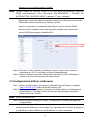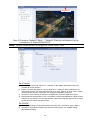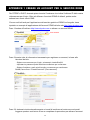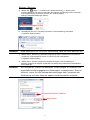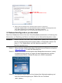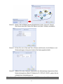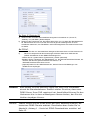
1
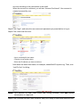
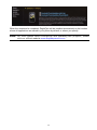
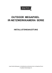
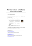
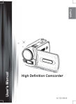
Powerful Remote Surveillance
Distance makes no difference
To Our Valuable Customers,
Thank you for choosing this product. You’ll be amazed by those useful
functions this product provides, especially for the powerful mobile
surveillance support.
Remote access via different platforms is widely supported:
a) For mobile platforms, iPhone®, BlackBerry®,
Nokia® Symbian®, Windows® Mobile & Android™
are available with our self-developed and free
program, EagleEyes, installed.
EagleEyes
b) For web browsers, Internet Explorer®, Mozilla®
Firefox®, Safari®, Google Chrome™ and Opera are
supported.
c) Apple’s media player, QuickTime®, is also one tool
you can use.
To monitor and control multiple network devices, you can also install our
free CMS software provided within the CD manual.
To know more about our mobile phone program, “EagleEyes”, and where to
download, please visit:
http://www.eagleeyescctv.com
To know more about feature applications, please visit:
www.eagleeyescctv.com/video
To know what’s new for our products, please visit:
www.eagleeyescctv.com/facebook
To seek for technical support, please contact:
[email protected]
To give us your precious suggestions and comments, please contact:
[email protected]
382Z
OUTDOOR IR
NETWORK CAMERA Series
INSTALLATION GUIDE
Please read instructions thoroughly before operation and retain it for future reference.
N263_263V_V1.3
IMPORTANT SAFEGUARD
All lead-free products offered by the company comply with the requirements of the European
law on the Restriction of Hazardous Substances (RoHS) directive, which means our
manufacture processes and products are strictly “lead-free” and without the hazardous
substances cited in the directive.
The crossed-out wheeled bin mark symbolizes that within the European Union the product
must be collected separately at the product end-of-life. This applies to your product and any
peripherals marked with this symbol. Do not dispose of these products as unsorted municipal
waste. Contact your local dealer for procedures for recycling this equipment.
Trademark Acknowledgements
iPhone® is the registered trademark of Apple Inc.
BlackBerry® and related trademarks, names and logos are the property of Research In Motion Limited and are
registered and/or used in the U.S. and countries around the world. Used under license from Research In Motion
Limited.
Android™ is a trademark of Google Inc. Use of this trademark is subject to Google Permissions.
Windows Mobile & Symbian mentioned in this document are the registered trademarks of their respective
holders.
Disclaimer
We reserve the right to revise or remove any content in this manual at any time. We do not warrant or assume
any legal liability or responsibility for the accuracy, completeness, or usefulness of this manual. The content of
this manual is subject to change without notice.
MPEG4 Licensing
THIS PRODUCT IS LICENSED UNDER THE MPEG4 VISUAL PATENT PORTFOLIO LICENSE FOR THE
PERSONAL AND NON-COMMERCIAL USE OF A CONSUMER FOR (i) ENCODING VIDEO IN COMPLIANCE
WITH THE MPEG4 VISUAL STANDARD (“MPEG-4 VIDEO”) AND/OR (ii) DECODING MPEG4 VIDEO THAT
WAS ENCODED BY A CONSUMER ENGAGED IN A PERSONAL AND NON-COMMERCIAL ACTIVITY
AND/OR WAS OBTAINED FROM A VIDEO PROVIDER LICENSED BY MPEG LA TO PROVIDE MPEG4
VIDEO. NO LICENSE IS GRANTED OR SHALL BE IMPLIED FOR ANY OTHER USE. ADDITIONAL
INFORMATION INCLUDING THAT RELATING TO PROMOTIONAL INTERNAL AND COMMERCIAL USES
AND LICENSING MAY BE OBTAINED FROM MPEG LA, LLC. SEE HTTP://WWW.MPEGLA.COM.
GPL Licensing
This product contains codes which are developed by Third-Party-Companies and
which are subject to the GNU General Public License (“GPL”) or the GNU Lesser
Public License (“LGPL”).
The GPL Code used in this product is released without warranty and is subject to the
copyright of the corresponding author.
Further source codes which are subject to the GPL-licenses are available upon
request.
We are pleased to provide our modifications to the Linux Kernel, as well as a few new
commands, and some tools to get you into the code. The codes are provided on
the FTP site, and please download them from the following site or you can refer to
your distributor:
http://download.dvrtw.com.tw/GPL/076D_Series/arm-linux-2.6.tar.gz
TABLE OF CONTENTS
1. OVERVIEW................................................................................................................................................. 1
1.1 Package content ........................................................................................................................................... 1
1.2 Dimensions ................................................................................................................................................... 1
1.3 Cable overview ............................................................................................................................................. 1
2. INSTALLATION & CONNECTION ............................................................................................................ 2
2.1 Install the camera.......................................................................................................................................... 2
2.2 Connect to power.......................................................................................................................................... 3
3. CAMERA CONNECTION TO INTERNET................................................................................................ 4
3.1 Camera Access via LAN ............................................................................................................................... 4
3.2 Network Configurations via Wizard............................................................................................................... 8
APPENDIX 1 CREATING AN ACCOUNT FOR DDNS SERVICE ...........................................................13
APPENDIX 2 MOBILE SURVEILLANCE VIA EAGLEEYES ...............................................................16
A2.1 Prerequisites............................................................................................................................................. 16
A2.2 Where to download .................................................................................................................................. 16
1. OVERVIEW
1.1 Package content
□
□
□
□
Network camera
□ Installation Sticker
Installation Guide
□ RJ45 cable extender adapter
Ground Wire
CD-ROM disc (including user manuals & CMS software “Video Viewer”)
1.2 Dimensions
117.89
287.4
212.63
246.87
241.03
1.3 Cable overview
CABLE
DESCRIPTION
RJ45 network cable
Connect it to the supplied RJ45 cable extender adapter for cable extension, and
prepare another RJ45 network cable with suitable length for your connection.
Reset wires
Remove the insulating coating of these two wires, and twist them together to reset
default. This will reset all parameters, including the IP address to factory default settings.
Note: Disconnect power before twisting these two wires together, and connect to power
again for reset default. When the reset is done, disconnect these two wires.
Power wires
Connect to AC power supply. For details, please refer to “2.2 Connect to power” at page
3.
1
2. INSTALLATION & CONNECTION
2.1 Install the camera
Note: The illustration below is for installation only, and the actual product may look
different from the illustration below.
2
2.2 Connect to power
Get a power cord and cut off its female connector side. Then, remove the insulating
coating to reveal positive, negative and ground wires.
Find the two wires labeled “L” (red) & “N” (black) on your camera, and remove a small
piece of their insulating coating to reveal the naked wires.
3
3. CAMERA CONNECTION TO INTERNET
Before using this network camera, please follow the instructions below to finish the
network connection settings based on your installation environment:
To configure the network settings, you must connect the camera to your PC by
LAN. For details, please refer to “Camera Access via LAN” at page 4.
To configure the network settings via Wizard, please refer to “3.2 Network
Configurations via Wizard” at page 8.
3.1 Camera Access via LAN
Step1: Connect this network camera and your PC via a RJ45 network cable, and make
sure the camera is powered on.
Step2: Set the PC’s IP address as “192.168.1.XXX” (1~255, except 10).
For Windows XP users:
a) Select “start” “Control Panel” “Network and Internet Connections” “Network
Connections” (If you’re in “Category View”).
4
b) In “LAN or High-Speed Internet”, right-click on “Local Area Connection”, and select
“Properties”.
c) In the “General” tab, select “Internet Protocol (TCP/IP)”, and select “Properties”.
d) In the “General” tab, select “Use the following IP address”, and set the IP address to
“192.168.1.XXX” (XXX can be any value from 1~255 except 10).
Note: It’s recommended to note down the current settings first and then change
as instructed. It’s helpful when you need to restore the computer’s
network settings for connecting to Internet later.
e) Click “OK” to close the “Internet Protocol (TCP/IP) Properties” dialog box. Then, click
“Close” to close the “Local Area Connection Properties” dialog box.
For Windows Vista users:
a) Select “ ” (start) “Control Panel” “Network and Internet” to enter the “Network and
Sharing Center”. Then, click “Manage network connections” (If you’re in “Category View”).
b) Right-click on “Local Area Connection”, and select “Properties”.
5
c) In the “Networking” tab, select “Internet Protocol Version 4 (TCP/IPv4)”, and select
“Properties”.
d) In the “General” tab, select “Use the following IP address”, and set the IP address as
described below.
Note: It’s recommended to note down the current settings first and then change
as instructed. It’s helpful when you need to restore the computer’s
network settings for connecting to Internet later.
e) Click “OK” to close the “Internet Protocol Version 4 (TCP/IPv4) Properties” dialog box. Then,
click “Close” to close the “Local Area Connection Properties” dialog box.
6
For Windows 7 users:
a) Select “ ” (start) “Control Panel” “Network and Internet” to enter the “Network and
Sharing Center”. Then, click “Change adapter settings”.
b) Right-click on “Local Area Connection”, and select “Properties”.
Note: If your local area connection is not enabled, please also enable it.
c) In the “Networking” tab, select “Internet Protocol Version 4 (TCP/IPv4)”, and select
“Properties”.
d) In the “General” tab, select “Use the following IP address”, and set the IP address as
described below.
Note: It’s recommended to note down the current settings first and then change
as instructed. It’s helpful when you need to restore the computer’s network
settings for connecting to Internet later.
7
e) Click “OK” to close the “Internet Protocol Version 4 (TCP/IPv4) Properties” dialog box. Then,
click “Close” to close the “Local Area Connection Properties” dialog box.
3.2 Network Configurations via Wizard
A quick installation wizard is available via your web browser for password change, date &
time settings, and network configurations.
Note: You can also change the settings in the system configuration page via your
web browser later. For details, please refer to “5. ACCESSING THE CAMERA
VIA WEB BROWSER” in the user manual.
Step1: Open your web browser, for example, Microsoft Internet Explorer, and enter
“http://192.168.1.10” in the URL address box.
Step2: In the login page, key in the default user name (admin) and password (admin),
and enter the security code from the image below. Then, click “LOGIN”.
Step3: The wizard is then starting analyzing your network environment, and shows your
network environment. Select “Next” to continue.
8
Step4: In “Account”, change the access password if needed.
If not, leave all the columns blank, and select “Next”.
Step5: In “Date and Time”, check if the date and time setting are correct and modify if
necessary.
Step6: In “Network”, select the network type based on your network environment (Static
IP / PPPoE / DHCP), and key in the information needed.
Note: This camera doesn’t support POE router or hub.
9
For Static IP:
a) Enter the information of “Server IP”, “Gateway” and “Net Mask” obtained from your ISP
(Internet Service Provider).
b) Enter the port number. The valid number ranges from 1 to 9999. The default value is 80.
Typically, the TCP port used by HTTP is 80. However in some cases, it is better to change
this port number for added flexibility or security.
For PPPoE:
a)
b)
Enter the user name and password obtained from your ISP.
Continue the DDNS setting by clicking the “DDNS” button, as reminded in this page.
- Select “default” in “System Name”.
- In “Hostname”, keep the default value, i.e. the MAC address of this camera. Then, note
down the whole address of the camera, for example,
MAC000E5318C04C.ddns.dvrtw.com.tw.
- (Optional) Enter your email address to receive messages from the DDNS server.
Note: Please at least use the default address to access your DVR remotely once.
This is to ensure our DDNS server has your DVR registered. Then, you may
change the host name to a more meaningful name to memorize later here.
Note: You can also create a DDNS account from a website which provides free
DDNS service. For details, please refer to “APPENDIX 1 CREATING AN
ACCOUNT FOR DDNS SERVICE” at page 13.
c)
Select “Save” and return to the wizard.
For DHCP:
a) Before selecting this option, you need to finish the DHCP router settings first.
Get a router and connect it to the Internet via your computer (with Static IP or PPPoE setting).
There are different setting methods for different routers. Please refer to their respective user
manuals.
10
b) Continue the DDNS setting by clicking the “DDNS” button, as reminded in this page.
- Select “default” in “System Name”.
- In “Hostname”, keep the default value, i.e. the MAC address of this camera. Then, note
down the whole address of the camera, for example,
MAC000E5318C04C.ddns.dvrtw.com.tw.
- (Optional) Enter your email address to receive messages from the DDNS server.
Note: Please at least use the default address to access your DVR remotely once.
This is to ensure our DDNS server has your DVR registered. Then, you may
change the host name to a more meaningful name to memorize later here.
Note: You can also create a DDNS account from a website which provides free
DDNS service. For details, please refer to “APPENDIX 1 CREATING AN
ACCOUNT FOR DDNS SERVICE” at page 13.
c) Select “Save” and return to the wizard.
Step7: In “Apply”, all the changes are listed. Check if the changes are correct.
‧ If yes, click “Save”.
‧ If no, click “Back” to where the changes should be made for modification, and click “Save” to
apply the settings.
You will be prompted to restart your web browser for network setting changes.
Note: You can also change the settings in the system configuration page via your
web browser later. For details, please refer to “5. ACCESSING THE CAMERA
VIA WEB BROWSER” in the user manual.
11
Step8: Click “Save” and log out. Then, disconnect your camera and your PC, and
connect them to Internet separately.
Step9: Enter the host name you just note down in the URL address box of the web
browser, and see if you can access the camera successfully.
12
APPENDIX 1 CREATING AN ACCOUNT FOR DDNS SERVICE
For PPPOE or DHCP, you should enter the host name which points to the IP address of your
network camera for login first. Besides using the default DDNS service, you can also apply
for new DNS services.
There are many websites for free DDNS service application, and below shows an example of
DDNS account application from the website http://www.dyndns.com.
Step1: Go to http://www.dyndns.com, and click “Create Account” to sign up a DDNS account.
Step2: Enter all the information necessary for signing up an account according to the website
instructions.
‧Key in a user name for login, for example, headoffice523.
‧Set the password and input it again to confirm.
‧Key in your E-mail address and input it again to confirm.
Then, click “Create Account”.
Step3: The system will automatically send a confirmation email to your email account.
Please read this email within 48 hours and complete the procedure to activate your
13
account according to the instructions in the email.
When the account is confirmed, you will see “Account Confirmed”. Your account is
created successfully now.
Step4: Click “login”, and enter the user name and password you preset before to log in.
Step5: Click “Add Host Services”.
‧Input a meaningful host name.
‧Choose a host system name.
‧Enter the IP address you want to redirect.
Note down the whole host name, for example, headoffice523.dyndns.org. Then, click
“Add To Cart” for billing.
Note: This service is free. Just finish the billing process, and NO paying
information is required.
Step6: Click “Activate Services” after checkout, and you’re ready to use DDNS services now.
14
Step7: Return to your web browser, and go to “Network” “DDNS”.
‧ Select “Enable” for DDNS.
‧ Select the system name you set when subscribing the DDNS service from the drop-down list, for
example, dyndns.
‧ Enter the user name & password you used to log into the DDNS service.
‧ Enter the host name you set when subscribing the DDNS service, for example, headoffice523.
15
APPENDIX 2 MOBILE SURVEILLANCE VIA EAGLEEYES
EagleEyes is a mobile phone program used with our surveillance system (DVRs or network
cameras) for remote surveillance. It has several advantages:
It’s free (Except EagleEyes Plus for iPhone).
It’s compatible with several popular mobile platforms, such as iPhone, BlackBerry, Symbian, Windows
Mobile and Android.
It’s easy to download, install and configure. For more details about configuring and
operating this program, please visit our official website www.eagleeyescctv.com.
A2.1 Prerequisites
Before installing EagleEyes to your mobile phone for remote surveillance, make sure you
have checked the following:
Your mobile platform is iPhone, BlackBerry, Symbian, Windows Mobile & Android.
Mobile Internet services are subscribed and available to use for your mobile phone.
Note: You might be charged for Internet access via wireless or 3G networks. For
the Internet access rate details, please check with your local network
operator or service provider.
Your DVR or network camera is powered on and connected to Internet.
You have noted down the IP address, port number, user name and password used to access your DVR or
network camera from Internet.
A2.2 Where to download
Connect to www.eagleeyescctv.com from your mobile phone, and sign in.
Note: Please DO NOT try to download EagleEyes from your computer.
Then, select “Software” and the mobile platform of your phone to download EagleEyes to
your phone.
For BlackBerry, Symbian, Windows Mobile & Android, select the download link from the website to start
downloading.
Note: It’s recommended to download EagleEyes for BlackBerry with the web
browser of Opera.
For iPhone, two versions of EagleEyes are available:
-- EagleEyes Plus (US$4.99), and
-- EagleEyes Lite (Free).
Select the version you want, and you’ll be directed to “App Store” to download the application.
Note: You can also find EagleEyes on “App Store” from your iPhone. Go to “App
Store”, and select “Search”. Enter the keyword “eagleeyes” to find and
download the version you want.
16
When the download is completed, EagleEyes will be installed automatically to the location
where all applications are saved in your phone by default, or where you specify.
Note: For more details about configuring and operating this program, please
visit our official website www.eagleeyescctv.com.
17
349Z
Telecamera IP con LED IR
da esterno
GUIDA ALL’INSTALLAZIONE
Leggere accuratamente le istruzioni prima dell’uso e conservarle per riferimenti futuri.
Italian_N36x_26x_V1.0
IMPORTANTI ISTRUZIONI DI SICUREZZA
Tutti i prodotti senza piombo forniti dall’azienda sono conformi ai requisiti delle Leggi Europee
in materia di restrizione dell’uso di determinate sostanze pericolose all’interno delle
apparecchiature elettriche ed elettroniche (RoHS), questo significa che le nostre procedure di
produzione ed in nostri prodotti sono rigorosamente “senza piombo” e privi delle sostanze
citate nella Direttiva.
Il simbolo del bidone della spazzatura annullato da una croce, indica che all’interno
dell’Unione Europea il prodotto deve essere smaltito separatamente dai rifiuti urbani al termine
della sua durata utile. Questo vale per il prodotto e per tutte le periferiche marcate con questo
simbolo. Non smaltire questi prodotti indistintamente insieme ai rifiuti urbani. Contattare il
proprio rivenditore locale per le procedure di riciclaggio dell’apparecchio.
Informazioni sui Marchi
Microsoft & Internet Explorer menzionati in questo documento sono marchi registrati dai rispettivi proprietari.
Limitazione delle responsabilità
Ci riserviamo il diritto di rivedere o rimuovere, in qualsiasi momento, qualsiasi contenuto di questo manuale.
Non facciamo garanzie, né ci assumiamo alcuna responsabilità legale nei riguardi dell’accuratezza,
completezza o utilità di questo manuale. I contenuti di questo manuale sono soggetti a modifica senza
preavviso.
Licenza MPEG4
QUESTO PRODOTTO E SOTTO LA LICENZA DEL PORTAFOGLIO LICENZE DI BREVETTI MPEG-4 VISUAL
PER USO PERSONALE NON COMMERCIALE DEGLI UTENTI PER LA (i) CODIFICA VIDEO IN
CONFORMITA ALLO STANDARD MPEG4 VISUAL (“VIDEO MPEG-4”) E/O (ii) LA DECODIFICA VIDEO
MPEG4 CHE E STATO CODIFICATO DA UN UTENTE IMPEGNATO IN UNA ATTIVITA PERSONALE E NON
COMMERCIALE E/O CHE E STATO OTTENUTO DA UN FORNITORE VIDEO AUTORIZZATO DA MPEG LA A
FORNIRE VIDEO MPEG4. NESSUNA ALTRA LICENZA E GARANTITA, NE DEVE CONSIDERASI IMPLICITA,
PER QUALSIASI ALTRO USO. ALTRE INFORMAZIONI, INCLUDENDO QUELLE RELATIVE AD USI
PROMOZIONALI INTERNI E COMMERCIALI ED ALLE CONCESSIONI DI LICENZA, POSSONO ESSERE
OTTENUTE DALLA MPEG LA, LLC. VISITARE IL SITO HTTP://WWW.MPEGLA.COM.
Licenza GPL
Questo prodotto contiene codici che sono sviluppati da Terze Parti e che sono
soggette a GNU General Public License (“GPL”) o a GNU Lesser Public Licence
(“LGPL”).
Il codice GPL utilizzato in questo prodotto viene rilasciato senza alcuna garanzia ed
è soggetto al copyright dell’autore.
Ulteriori codici sorgente soggetti a licenze GPL, sono disponibili su richiesta.
Siamo lieti di fornire le nostre modifiche al Linux Kernel, oltre ad alcuni comandi
nuovi, ed alcuni strumenti per accedere al codice. I codici sono disponibili sul sito
FTP, si raccomanda di scaricarli dal seguente sito oppure consultare il proprio
distributore:
ftp://ftp.dvrtw.com.tw/GPL/AV074/
1
CONTENUTI
1. PANORAMICA .........................................................................................................................1
1.1 Contenuto della confezione .......................................................................................................................... 1
1.2 Dimensioni .................................................................................................................................................... 1
1.3 Panoramica Cavo ......................................................................................................................................... 1
2. INSTALLAZIONE E COLLEGAMENTO ...................................................................................3
2.1 Installare la Telecamera ................................................................................................................................ 3
2.2 Collegare all’alimentazione........................................................................................................................... 4
3. CONNESSIONE ETHERNET ..................................................................................................6
3.1 Connessione di rete via LAN ........................................................................................................................ 6
3.2 Configurazioni di Rete via Wizard............................................................................................................... 10
3.2.1 Impostazioni in Wizard .................................................................................................................... 10
3.2.2 Impostazione DDNS........................................................................................................................ 12
3.3 Configurazioni di Rete via Browser............................................................................................................. 14
APPENDICE 1 CREARE UN ACCOUNT PER IL SERVIZIO DDNS..........................................17
APPENDICE 2 CONFIGURAZIONI IVS ....................................................................................20
A2.1 Intelligent Video System ........................................................................................................................... 20
A2.2 Face Tracking ........................................................................................................................................... 22
APPENDICE 3 OPERAZIONI DIGITAL PTZ (DPTZ). ................................................................23
1
1. PANORAMICA
1.1 Contenuto della confezione
□
□
□
□
Telecamera di Rete
□ Posizionamento Sticker
Guida all’installazione
□ Extender adattatore per cavo RJ45
Messa a Terra (Disponibile solo per il Modello 3)
CD-ROM (comprende il manuale d’uso e il software CMS “Video Viewer”)
1.2 Dimensioni
282.4
117.89
212.63
246.87
236.03
1.3 Panoramica Cavo
Per Modello Tipo AC
Cavo di rete RJ45
Cavi di Reset
Cavi di Alimentazione
CAVO
DESCRIZIONE
Cavo di rete RJ45
Connetterlo all’extender adattatore per cavo RJ45 in dotazione per prolungare il cavo e
preparare un secondo cavo di rete RJ45 della lunghezza giusta per il vostro
collegamento.
Rimouvere il rivestimento isolante di questi due cavi e avvolgerli insieme per resettare il
default. Questo resetterà tutti i paramentri, incluso l’indirizzo IP e li riporterà alle
impostazioni di default di fabbrica.
Nota: Scollegare l’alimentazione prima di avvolgere insieme questi due cavi e ricollegare
nuovamente l’alimentazione per resettare il default. Quando il reset sarà stato
eseguito, scollegare questi due cavi.
Collegare l’alimentatore AC. Fare riferimento alla sezione “2,2 Collegare l’alimentazione”,
a pagina 4, per i dettagli.
Cavi di Reset
Cavi di Alimentazione
1
Per Modello Tipo DC
Cavo di rete RJ45
Cavi di Reset
Cavo di Alimentazione
CAVO
DESCRIZIONE
Cavo di rete RJ45
Connetterlo all’extender per cavo RJ45 in dotazione per prolungare il cavo e
preparare un secondo cavo di rete RJ45 della lunghezza giusta per il vostro
collegamento.
Cavi di Reset
Rimouvere il rivestimento isolante di questi due cavi e avvolgerli insieme per resettare
il default. Questo resetterà tutti i parametri, incluso l’indirizzo IP e li riporterà alle
impostazioni di default.
Nota: Scollegare l’alimentazione prima di avvolgere insieme questi due cavi e
ricollegare nuovamente l’alimentazione per resettare il default.
Cavo di Alimentazione
Collegare all’alimentatore 12V DC.
2
2. INSTALLAZIONE E COLLEGAMENTO
2.1 Installare la Telecamera
Nota: L’illustrazione di seguito riguarda unicamente l’installazione ed il prodotto
reale potrebbe essere diverso da come viene rappresentato nell’illustrazione.
Posa dei cavi
lungo il muro
Posa dei cavi
dietro il muro
OPPURE
Praticare un foro
con il trapano
Incollare lo sticker in dotazione nel posto in
cui la videocamerà verrà installata. A
seconda dell’ambiente in cui installare la
videocamera, con l’aiuto di un trapano
praticare un foro nel centro dello sticker per i
cavi di alimentazione e video che in seguito,
se necessario, verranno fatti passare
attraverso.
Stringere leggermente le viti ad (a) e (b)
come indicato e assicurarsi che le viti non
siano troppo strette.
1) A seconda dell’ambiente in cui installare la videocamera far passare il cavo di alimentazione ed
il cavo video attraverso il sostegno per collegarli alla videocamera.
3-1 -- Il cavo è nascosto dall’altra parte del muro.
3-2 -- Il cavo corre lungo il muro.
2) Agganciare il sostegno e la videocamera con la vite utilizzata nella Fase 2 e spingerla per
fissare il sostegno.
3) Assicurare le viti su (a) e (b) e stringere le altre due viti a (c) e (d) per fissare il sostegno.
NOTA: Mentre si assicurano le viti è essenziale collegare il cavo di messa a terra in
dotazione (e) di colore giallo e verde (se trovato nella confezione).
3
Regolare gli angoli della videocamera:
(e) -- Regolare l’angolo verticale della videocamera e fissarlo con la vite e la chiave fornite con il
sostegno.
(f) -- Allentare leggermente la vite sulla giuntura della videocamera servendosi della chiave in
dotazione per regolare l’angolo orizzontale della videocamera e fissarlo.
2.2 Collegare all’alimentazione
Per Modello Tipo AC
Prendere un cavo di alimentazione e tagliare il lato della presa femmina. Quindi rimuovere il
rivestimento isolante per esporre il cavo positivo, il negativo e la messa a terra.
Tagliare la presa femmina e il rivestimento
isolante per esporre il cavo positivo, il negativo e
la messa a terra.
Individuare i due cavi etichettati con una "L" (rosso) e una "N" (nero) sulla vostra
videocamera e rimuovere una piccola parte del rivestimento isolante per esporre i fili.
Cavo di rete RJ45
Cavi di Reset
Cavi di Alimentazione
4
Avvolgere insieme i cavi della videocamera e dell’alimentazione facendo attenzione a
rispettare gli elettrodi (positivo con positivo, negativo con negativo, ignorando la messa
a terra). In seguito ricoprire i cavi con del nastro isolante.
Ricoperti con
il nastro
isolante.
N (nero)
L (rosso)
Per Modello Tipo DC
Collegare all’alimentatore (opzionale) alla spina della videocamera e alla presa di
alimentazione.
Cavo di rete RJ45
Cavi di Reset
Cavo di Alimentazione
Nota: L’alimentatore regolato 12V DC è adatto per il funzionamento di questo
dispositivo.
5
3. CONNESSIONE ETHERNET
Prima di utilizzare la videocamera in rete, seguire le istruzioni qui di seguito per
completare le impostazioni di connessione di rete basandovi sul vostro ambiente di
connessione.
Per configurare le impostazioni di rete, bisogna connettere la videocamera ad un
PC via LAN. Per i dettagli, fare riferimento alla sezione “3.1 Connessione di rete via
LAN”a pagina 6.
Per configurare le impostazioni di rete attraverso il wizard di impostazione, fare
riferimento alla sezione "3.2 Configurazioni di Rete via Wizard" a pagina 10.
Per configurare le impostazioni di rete attraverso un browser, fare riferimento alla
sezione "3.3 Configurazioni di Rete via Browser" a pagina 14.
3.1 Connessione di rete via LAN
Fase 1: Collegare questa videocamera e il vostro PC attraverso un cavo di rete RJ45, e
assicurarsi che la videocamera sia accesa.
Fase 2: Impostare l’indirizzo IP del PC come segue: "192.168.1.XXX" (1 ~ 255, eccetto
10).
Per gli utilizzatori di Windows 2000:
a) Selezionare "Start" → "Settings" → "Network and Dial-up Connections" (Connessioni di Rete
e Dial-up).
b) Fare clic con il tasto destro su “Local Area Connection” (Connessione area locale), quindi
selezionare “Properties” (Proprietà).
Proprietà
c) In "General" (Generale), selezionare "Internet Protocol (TCP/IP)" (Protocollo Internet), e
selezionare "Properties" (Proprietà).
Protocollo Internet (TCP/IP)
Proprietà
6
d) In "General" (Generale), selezionare "Use the following IP address", (Usare il seguente
indirizzo IP) e impostare l’indirizzo IP come descritto di seguito.
Nota: Si consiglia prima di annotare le impostazioni correnti e in seguito di
cambiarle come suggerito. E’ utile quando si ha bisogno di ripristinare le
impostazioni di rete del PC per connettersi a Internet in seguito.
192.168.1.XXX
(1 ~ 255 eccetto 10)
e) Cliccare su "OK" per chiudere la finestra di dialogo "Internet Protocol (TCP/IP) Properties"
(Proprietà Protocollo Internet). Quindi, cliccare su "Close" (Chiudi) per chiudere la finestra di
dialogo "Local Area Connection Properties" (Proprietà di connessione Area Locale).
Per gli utilizzatori di XP:
a) Selezionare "start" → "Control Panel" (Pannello di Controllo) → "Network and Internet
Connections" (Rete e Connessioni Internet)→ "Network Connections" (Connessioni di Rete)
(se siete in "Category View").
Rete e Connessioni Internet
Connessioni di Rete
7
b) In "LAN or High-Speed Internet", (LAN o Internet Alta Velocità) cliccare con il tasto destro su
"Local Area Connection" (Connessione Area Locale) e selezionare "Properties" (Proprietà).
Proprietà
c) In "General" (Generale), selezionare "Internet Protocol (TCP/IP)" (Protocollo Internet), e
selezionare "Properties" (Proprietà).
d) In "General" (Generale), selezionare "Use the following IP address", (Usare il seguente
indirizzo IP) e impostare l’indirizzo IP come"192.168.1.XXX" (XXX può essere qualunque
valore da 1 ~ 255 eccetto 10).
Nota: Si consiglia prima di annotare le impostazioni correnti e in seguito di
cambiarle come suggerito. E’ utile quando si ha bisogno di ripristinare le
impostazioni di rete del PC per connettersi a Internet in seguito.
e) Cliccare su "OK" per chiudere la finestra di dialogo "Internet Protocol (TCP/IP) Properties"
(Proprietà Protocollo Internet). Quindi, cliccare su "Close" (Chiudi) per chiudere la finestra di
dialogo "Local Area Connection Properties" (Proprietà di connessione Area Locale).
Per gli utilizzatori di Vista:
a) Selezionare " " (start) → "Control Panel" (Pannello di Controllo)→ "Network and Internet"
(Rete e Internet) per accedere al "Network and Sharing Center".(Centro Rete e Condivisione).
Quindi, cliccare su "Manage network connections"(Gestisci connessioni di rete) (Se siete in
"Category View").
Gestisci connessioni di rete
b) Fare clic con il tasto destro su “Local Area Connection” (Connessione area locale), quindi
selezionare “Properties” (Proprietà).
c) In "Networking" (Rete) selezionare "Internet Protocol Version 4 (TCP/IPv4)" (Protocollo
Internet Versione 4) e selezionare "Proprietà".
8
Internet Protocol Version 4 (TCP/IPv4) Properties
Proprietà
d) In "General" (Generale), selezionare "Use the following IP address", (Usare il seguente
indirizzo IP) e impostare l’indirizzo IP come descritto di seguito.
Nota: Si consiglia prima di annotare le impostazioni correnti e in seguito di
cambiarle come suggerito. E’ utile quando si ha bisogno di ripristinare le
impostazioni di rete del PC per connettersi a Internet in seguito.
192.168.1.XXX
(1 ~ 255 eccetto 10)
e) Cliccare su "OK" per chiudere la finestra di dialogo "Internet Protocol Version 4 (TCP/IPv4)
Properties" (Proprietà Protocollo Internet versione 4). Quindi, cliccare su "Close" (Chiudi) per
chiudere la finestra di dialogo "Local Area Connection Properties" (Proprietà di connessione
Area Locale).
9
3.2 Configurazioni di Rete via Wizard
Solo per dei modelli selezionati, è disponibile un wizard di installazione via browser per
cambiare la password, le impostazioni di data e orario e le configurazioni di rete.
Per dettagli sul wizard, consultare la sezione "3.2.1 Setting in Wizard" (Impostazioni
in Wizard) a pagina 10.
Per i dettagli sull’impostazione DDNS per PPPoE e DHCP, fare riferimento alla
sezione "3.2.2 DDNS Setting" (Impostazione DDNS) a pagina 12.
Nota: Le impostazioni nella pagina di configurazione del sistema possono essere
modificate in seguito anche attraverso il web browser. Per i dettagli fare
riferimento alla sezione "3.3 Configurazioni di Rete via Browser" a pagina 14.
3.2.1 Impostazioni in Wizard
Fase 1: Aprite il vostro browser, per esempio, Microsoft Internet Explorer, e digitate
"http://192.168.1.10" nella finestra dell’indirizzo URL.
Fase 2: Nella pagina di login digitare lo user name di default (admin) e la password di
default (admin), e inserire il codice di sicurezza dell’immagine sottostante.
Quindi cliccare su "LOGIN".
Fase 3: Il wizard comincerà quindi ad analizzare il vostro ambiente di rete e lo
visualizzerà. Selezionare "Next" (Prossimo) per continuare.
Fase 4: In "Account" (Conto), cambiare la password di accesso se necessario.
In caso contrario, lasciare vuote tutte le colonne e selezionare "Next"
(Prossimo).
Fase 5: In "Date and Time"(Data e Orario) controllare che le impostazioni della data e
dell’ora siano esatte e modificarle se necessario.
10
Fase 6: In "Network" (Rete), selezionare il tipo di rete a seconda del vostro ambiente di
rete (Static IP/PPPoE/DHCP), e digitare le informazioni necessarie.
Nota: Questa videocamera non supporta router POE o hub.
Per IP statico:
a) Inserire le informazioni di "Server IP", "Gateway" e "Net Mask" ottenute dal vostro ISP
(Provider di Servizi Internet).
b) Inserire il numero della porta. Il numero valido va da 1 a 9999. Il valore predefinito è 80.
Tipicamente la porta TCP usata dal protocollo HTTP è 80. Tuttavia, in alcuni casi, è meglio
cambiare questo numero di porta per una maggiore flessibilità o protezione.
Per PPPOE:
a) Inserire lo username e la password ottenute dal vostro ISP.
b) Continuare l’impostazione DDNS come spiegato nella sezione "3.2.2 DDNS
Setting"(Impostazione DDNS) quando vi viene richiesto di riavviare il browser nella Fase 8.
Per DHCP:
a) Prima di selezionare questa opzione, bisogna completare l’impostazione del router DHCP.
Prendere un router e collegarlo a Internet tramite il PC (con impostazioni IP statico o PPPoE).
Sono disponibili diversi metodi di impostazione in relazione ai diversi router. Fare riferimento
ai rispettivi manuali d’uso.
b) Continuare l’impostazione DDNS come spiegato nella sezione "3.2.2 DDNS
Setting"(Impostazione DDNS) quando vi viene richiesto di riavviare il browser nella Fase 8.
Fase 7: In "Apply" (Applica) sono elencati tutti i cambiamenti. Controllare che i
cambiamenti siano corretti.
‧ Se si, cliccare su "Save"(Salva).
‧ Se no, cliccare su "Back" (Indietro) dove bisogna apportare i cambiamenti per la modifica e
cliccare su "Save" (salva) per applicare le impostazioni.
11
Nota: Le impostazioni nella pagina di configurazione del sistema possono essere
modificate in seguito anche attraverso il web browser. Per i dettagli,
consultare la sezione 5 ACCEDERE ALLA VIDEOCAMERA ATTRAVERSO IL
WEB BROWSER" nel manuale di istruzioni.
Fase 8: Vi verrà richiesto di riavviare il browser per rendere effettivi i cambiamenti
dell’impostazione di rete.
‧ Per PPPoE e DHCP, continuare come spiegato nella sezione "3.2.2 Impostazione DDNS”.
‧ Per IP Statico, disconnettere la videocamera e il PC e connetterli a Internet separatamente.
In seguito, inserire l’indirizzo IP della videocamera nella finestra dell’indirizzo URL del
browser e vedere se si riesce ad accedere alla videocamera.
3.2.2 Impostazione DDNS
Fase 1: Effettuare nuovamente il login nella videocamera e selezionare "Close" (Chiudi)
per il controllo dell’ambiente di rete.
12
Fase 2: Nella live page, cliccare su "Config." (Configura) o "Configuration" (Configura)
per accedere alla pagina di configurazione.
Nota: Modelli diversi di telecamera potrebbero avere live view e pagine di
configurazione differenti. Le immagini qui riportate sono a titolo di esempio
e potrebbero essere differenti dal prodotto in vostro possesso.
Configurazioni
Fase 3: Cliccare su "Network" (Rete) → "DDNS", e controllare "Attiva DDNS”.
Fase 4: Selezionare "default" o l’hostname che avete utilizzato per il servizio DDNS in
"System Name" (ex. dyndns).
Quando è possibile scegliere "default”
In "Hostname", mantenere il valore di default, cioè l’indirizzoMAC di questa
videocamera, o cambiare il nome con uno che abbia un significato.
Dopo annotare l’intero indirizzo della videocamera, per esempio
MAC000E530D93E3.ddns.dvrtw.com.tw.
Nome del sistema: default
13
Quando non è possibile scegliere "default”
Nota: Dovete creare un account DDNS su un sito web che fornisce il servizio
DDNS gratuitamente. Fare riferimento alla“APPENDICE 1 CREARE UN
ACCOUNT PER I SERVIZI DDNS” a pagina 17 per i dettagli.
Selezionare il nome del sistema impostato durante la sottoscrizione del servizio
DDNS dalla finestra a tendina, per esempio, dyndns.
Inserire lo username e la password utilizzati per il login al servizio DDNS.
Quindi inserire l’hostname che avete impostato quando avete sottoscritto il
servizio DDNS per esempio, headoffice523.
User Name per il login al Servizio DDNS
Password per il login al Servizio DDNS
Fase 5: Cliccare su "Save" (Salva) ed effettuare il logout. Dopo, disconnettere la
videocamera e il PC e connetterli a Internet separatamente.
Fase 6: Inserire l’hostname annotato nella finestra dell’indirizzo URL del browser e
vedere se si riesce ad accedere alla videocamera.
3.3 Configurazioni di Rete via Browser
Fase 1: Aprite il vostro browser, per esempio, Microsoft Internet Explorer, e digitate
"http://192.168.1.10" nella finestra dell’indirizzo URL.
Fase 2: Nella pagina di login digitare lo username di default (admin) e la password di
default (admin), e inserire il codice di sicurezza dell’immagine sottostante.
Quindi cliccare su "LOGIN".
Nota: Salta il wizard se c’è.
Fase 3: Nella live page, cliccare su "Config." (Configura) per accedere alla pagina di
configurazione.
Nota: Modelli diversi di videocamera potrebbero avere live view e pagine di
configurazione differenti. Le immagini qui riportate sono a titolo di esempio
e potrebbero essere differenti dal prodotto in vostro possesso.
14
Configurazioni
Fase 4: Cliccare su "Network" (Rete) → "Network" (Rete) per selezionare il tipo di
connessione: IP Statico/PPPoE/DHCP.
Nota: Questa videocamera non supporta router POE o hub.
Per IP statico:
a) Inserire le informazioni di "Server IP", "Gateway" e "Net Mask" ottenute dal vostro ISP
(Provider di Servizi Internet).
b) Inserire il numero della porta. Il numero valido va da 1 a 9999. Il valore predefinito è 80.
Tipicamente la porta TCP usata dal protocollo HTTP è 80. Tuttavia, in alcuni casi, è meglio
cambiare questo numero di porta per una maggiore flessibilità o protezione.
c) Cliccare su "Save" (Salva) per salvare le configurazioni di rete ed effettuare il logout.
d) Disconnettere la videocamera e il PC e connetterli a Internet separatamente. Quindi inserire
l’indirizzo IP o l’hostname che avevate annotato nella finestra dell’URL del browser e vedere
se riuscite ad accedere alla videocamera.
Per PPPOE:
a) Inserire lo username e la password ottenuti dal vostro ISP e cliccare su "Save" (Salva).
b) Continuare l’impostazione DDNS come descritto nella sezione "3.2.2 DDNS Setting"
(Impostazione DDNS).
15
Per DHCP:
a) Prima di selezionare questa opzione, bisogna completare l’impostazione del router DHCP.
Prendere un router e collegarlo a Internet tramite il PC (con impostazioni IP statico o PPPoE).
Sono disponibili diversi metodi di impostazione in relazione ai diversi router. Fare riferimento
ai rispettivi manuali d’uso.
b) Continuare l’impostazione DDNS come descritto nella sezione "3.2.2 DDNS Setting"
(Impostazione DDNS).
16
APPENDICE 1 CREARE UN ACCOUNT PER IL SERVIZIO DDNS
Per PPPOE o DHCP, dovreste prima inserire l’hostname che indica l’indirizzo IP della vostra
videocamera per il login. Oltre ad utilizzare il servizio DDNS di default, potete anche
sottoscrivere nuovi servizi DNS.
Ci sono molti siti web per l’applicazione del servizio gratuito di DDNS e di seguito viene
riportato un esempio di applicazione dell’account DDNS dal sito web http://www.dyndns.com.
Fase 1: Andare all’indirizzo http://www.dyndns.com e attivare un account DDNS.
Crea account
Fase 2: Inserire tutte le informazioni necessarie per registrare un account, in base alle
istruzioni del sito.
‧Digitare uno username per il login, ad esempio, headoffice523.
‧Impostare la password quindi inserirla nuovamente per confermare.
‧Digitare l’indirizzo e-mail quindi inserirlo nuovamente per confermare.
Quindi, fare clic su “Create Account” (Crea account).
Crea account
Fase 3: Il sistema invierà automaticamente un’email di conferma al vostro account email.
Leggere questa e-mail entro 48 ore e completare la procedura per attivare l’account
17
in relazione alle istruzioni contenute nell’e-mail.
Quando l’account è confermato vedrete il messaggio “Account Confermato”. Adesso
l’account è creato.
Fase 4: Cliccare su “login” e inserire nome utente e password predefinite prima di accedere.
Fase 5: Fare clic su “Add Host Services” (Aggiungi servizi host).
Aggiungi servizi host
‧Inserire un host name che abbia un significato.
‧Scegliere un nome dell’ host system.
‧Inserire l’indirizzo IP che si vuole reindirizzare.
Annotare l’intero hostname, ad esempio, headoffice523.dyndns.org. Quindi cliccare
su "Add To Cart" (Aggiungere al carrello) per la fatturazione.
Aggiungere al carrello
Nota: Questo servizio è gratuito. Terminare il processo di fatturazione e NON
viene richiesta nessuna informazione di pagamento.
Fase 6: Cliccare su "Activate Services" (Attivare Servizi) dopo il checkout, e adesso siete
pronti per utilizzare i servizi DDNS.
18
Attivare Servizi
Fase 7: Ritornare al vostro browser e andare a "Network" (Rete)→ "DDNS". Seguire le
istruzioni nella sezione "3.2.2 DDNS Setting" (Impostazione DDNS) a pagina 12.
19
APPENDICE 2 CONFIGURAZIONI IVS
Le funzioni relative all’IVS sono raggruppate in due categorie e non è consentito attivarle
contemporaneamente.
Intelligent Video System (Sistema Video Intelligente) (Flow Counting/Virtual Fence/One
Way Pass) (Conteggio Flusso/Recinto Virtuale/Passaggio Unidirezionale)
La videocamera riconosce il volto umano e ne segue i movimenti
Nota: Questa funzione è disponibile solo per i modelli Megapixel.
Nota: Questa funzione non è disponibile quando il formato di riproduzione
selezionato è MJPEG.
A2.1 Intelligent Video System
Nota: Quando questa funzione è attiva, non è consentito l’uso di DPTZ, Face
Tracking, Smart Zoom e dello zoom ottico.
Intelligent Video System vi permette di scegliere tra Flow Counting (Conteggio di Flusso),
Virtual Fence (Recinto Virtuale), o One-Way Pass (Passaggio Unidirezionale) a seconda
dell’ambiente di installazione della videocamera.
Intelligent Video System
FASE 1: Cliccare su "IVS" per accedere alla pagina di configurazione del sistema IVS e
selezionare "Intelligent Video System".
FASE 2: Selezionare e impostare il sistema IVS come descritto di seguito.
20
ELEMENTO
DESCRIZIONE
Enable (Attivare)
Selezionare "ON" per attivare o "OFF" per disattivare la funzione selezionata in
"Tracking Mode" (Modalità Inseguimento).
Tracking Mode
(Modalità Inseguimento)
Selezionare "Flow Counting",(Conteggio di Flusso) "Virtual Fence" (Recinto
Virtuale) o "One Way Pass" (Passaggio Unidirezionale) dall’elenco a tendina.
Reverse (Contrario)
Disegnare una linea di rilevamento direttamente sull’area di anteprima di live
view sopra "Reverse" (Contrario) e cliccarla per decidere l’orientamento del
rilevamento a seconda di ciò che avete selezionato in "Tracking Mode"
(Modalità Inseguimento).
Per Flow Counting (Conteggio di Flusso):
IN (ENTRATA):
OUT (USCITA):
Una persona che proviene dalla direzione opposta a
quella indicata dalla freccia.
Una persona che proviene dalla stessa direzione
indicata dalla freccia.
Per Virtual Fence (Recinto Virtuale):
Si verifica un evento tutte le volte che qualcuno attraversa la linea di
rilevamento.
Per One Way Pass (Passaggio Unidirezionale):
Si verifica un evento tutte le volte che qualcuno proviene dalla direzione
opposta a quella indicata dalla freccia.
Sensitivity (sensibilità)
Permette di impostare la sensibilità per IVS da 00 a 15. Maggiore è il valore,
maggiore sarà la sensibilità dell’IVS.
Line Display (Visualizza
Linea)
Selezionare per visualizzare (ON) o nascondere (OFF) la linea di rilevamento
per IVS su live view.
Reset Count (Reset dei
Contatori)
Resettare il conteggio di flusso su 0 quando la modalità inseguimento è
impostata su “CONTEGGIO FLUSSI” ed è attiva.
FASE 3: Quando tutte le configurazioni saranno complete, cliccare su "Save" (Salva) per
salvare i cambiamenti e cliccare "Live" in alto per ritornare al live view.
Quando "Flow Counting" (Conteggio di Flusso) è selezionato ed attivo, vedrete il
pannello di conteggio di flusso così come viene mostrato nel pannello a sinistra di
live view.
21
A2.2 Face Tracking
Nota: Quando questa funzione è attiva, non è consentito l’uso di DPTZ, Intelligent
Video System, Smart Zoom e dello zoom ottico.
La funzione Face Tracking è utilizzata in particolare per zoomare sul viso dell’intruso, in
modo da poterlo identificare facilmente.
FASE 1: Cliccare su "IVS" (Intelligent Video System) per accedere alla pagina di
configurazione del sistema IVS e selezionare " Face Tracking".
FASE 2: Selezionare ed impostare la funzione Face Tracking come descritto di seguito.
ELEMENTO
DESCRIZIONE
Face Detection
(Rilevamento Viso)
Selezionare "Enable" (Attiva) per attivare o "Disable" (Disattiva) per disattivare
questa funzione.
OSD
Selezionare "ON" per visualizzare i seguenti messaggi di stato su live view:
FACE STANDBY:
Questa funzione è attiva e pronta all’uso.
FACE TRACKING:
E’ una funzione di inseguimento.
ZOOMA/APRI SU
VOLTO:
E’ una funzione di zoom sul volto per
stringere/allargare quando il soggetto
dell’inseguimento lascia l’area di sorveglianza.
Sensitivity (sensibilità)
Imposta la sensibilità della funzione di inseguimento tra HIGH/MEDIUM/LOW
(ALTA/MEDIA/BASSA).
Resolution (Risoluzione)
Imposta la risoluzione per il face tracking tra Auto/VGA/QVGA.
FASE 3: Quando tutte le configurazioni saranno complete, cliccare su "Save" (Salva) per
salvare i cambiamenti e cliccare "Live" in alto per ritornare al live view.
22
APPENDICE 3 OPERAZIONI DIGITAL PTZ (DPTZ).
Questa videocamera di tipo fisso ha la funzione PTZ , cioè. digital PTZ (movimento in
orizzontale, movimento in verticale e controllo focale dell’obiettivo digitali)(di qui in avanti
chiamato “DPTZ”), per il monitoraggio di un’area ampia.
Nota: Questa funzione è disponibile solo per i modelli Megapixel.
Nota: Quando questa funzione è attiva, non è consentito l’uso di Intelligent Video
System, DPTZ, Face Tracking, Smart Zoom e dello zoom ottico.
FASE 1: Cliccare su "DPTZ" per visualizzare il pannello di controllo DPTZ.
Pan/tilt
disponibil
i dopo lo
zoom.
FASE 2: Selezionare le funzioni quando necessario.
ICONA
/
FUNZIONE
Adatta allo schermo /
Ritorna alla dimensione
originale
DESCRIZIONE
Sono disponibili diverse risoluzioni. Quando la risoluzione
selezionata non è inclusa nel vostro supporto live view, una parte
dell’area di sorveglianza potrebbe essere coperta sullo schermo e
dovrete quindi muovervi manualmente sullo schermo per
controllarla.
Viene utilizzato per diminuire la risoluzione selezionata per
: adattarla alla dimensione del live view corrente.
Viene utilizzato per ripristinare la dimensione originale della
: risoluzione precedentemente diminuita.
Prendere delle
istantanee
Cliccare per scattare delle istantanee della visualizzazione corrente
e salvare dove specificato in "Config." (Configura) → "Camera"
(Telecamera)→ "Camera" (Telecamera)→ "Snapshot Path"
(Percorso Istantanea).
Attiva Modalità Auto
Cliccare per attivare la modalità auto della videocamera. La
modalità auto potrebbe essere "Sequence" (Sequenza) o "Auto
Pan" (Movimento in orizzontale auto) specificato in "Config."
(Configura)→ "Camera" (Telecamera) → "Cruise" (Muovi) →
"Active Mode" (Modalità Attiva).
Nota: Questa funzione è disponibile solo quando il DPTZ è inattivo.
23
ICONA
FUNZIONE
DESCRIZIONE
Sequenza: Muovi su diversi punti prestabiliti come specificato in
"Config." (Configura)→ "Camera" (Telecamera)→
"Cruise" (Muovi)→ "Active Mode" (Modalità Attiva) →
"Sequence" (Sequenza).
Nota: I punti prestabiliti sono in "Config." (Configura)
→ "Camera" (Telecamera)→ "Preset"
(Prestabilito).
Panoramica
Panoramica automatica ed orizzontale.
automatica:
Attiva DPTZ
Cliccare per attivare la funzione DPTZ. Quando questa funzione è
attiva, sono disponibili le seguenti operazioni:
Modalità Auto
Muovi sopra/sotto/sinistra/destra dopo lo zoom digitale.
/
Ingrandimento /
riduzione digitale*
Cliccare per eseguire lo zoom ottico avanti/indietro dell’immagine.
/
Zoom ottico avanti /
indietro*
Cliccare per ingrandire l’immagine/ridurre l’immagine alle
dimensioni originali con zoom ottico.
* Disponibile solo per i modelli di videocamera tipo AC Megapixel.
24
Outdoor-IRNetzwerkkameraserie
Installationsanleitung
Bitte lesen Sie die Anweisungen vor der Inbetriebnahme aufmerksam durch und bewahren sie zum
zukünftigen Nachschlagen auf.
DE_N263_263V_V1.3
Wichtige Sicherheitshinweise
Sämtliche von unserem Unternehmen angebotenen bleifreien Produkte erfüllen die
Anforderungen der europäischen Richtlinie zur Beschränkung der Verwendung gefährlicher
Substanzen (RoHS). Dies bedeutet, dass sowohl der Herstellungsprozess als auch die
Produkte absolut ohne Blei und sämtliche in der Richtlinie aufgeführten gefährlichen
Substanzen auskommen.
Das Symbol mit einer durchgestrichenen Abfalltonne auf Rädern bedeutet, dass das Produkt
innerhalb der europäischen Union am Ende seiner Lebensdauer separat gesammelt und
entsorgt werden muss. Dies gilt für das Produkt selbst sowie für sämtliche Peripheriegeräte,
die mit diesem Symbol gekennzeichnet sind. Entsorgen Sie diese Produkte nicht mit dem
unsortierten Hausmüll. Weitere Informationen zum Recycling dieses Gerätes erhalten Sie bei
Ihrem örtlichen Fachhändler.
Anerkennung der Markenrechte
iPhone® ist eine eingetragene Marke der Apple Inc.
BlackBerry® und die zugehörigen Marken, Namen und Logos sind Eigentum von Research In Motion Limited;
sie sind in den Vereinigten Staaten und anderen Ländern weltweit eingetragen und/oder werden dort verwendet.
Verwendet in Lizenz von Research In Motion Limited.
Android™ ist eine Marke der Google Inc. Die Nutzung dieser Marke unterliegt den Google-Genehmigungen
(Google Permissions).
Die in diesem Dokument erwähnten Begriffe Windows Mobile & Symbian sind eingetragene Marken ihrer
jeweiligen Inhaber.
Haftungsausschluss
Wir behalten uns das Recht vor, die Inhalte dieser Anleitung jederzeit zu überarbeiten oder Teile daraus zu
entfernen. Wir geben keinerlei Zusicherungen und übernehmen keine rechtsgültige Haftung hinsichtlich
Exaktheit, Vollständigkeit oder Nutzbarkeit dieser Anleitung. Die Inhalte dieser Anleitung können ohne
Vorankündigung geändert werden.
MPEG 4-Lizenzierung
Dieses Produkt ist durch die „MPEG4 Visual Patent Portfolio“-Lizenz für den persönlichen und
nichtkommerziellen Einsatz durch den Endkunden zur (I) Codierung von Videodaten in Übereinstimmung mit
dem MPEG4-Standard („MPEG-4 Video“) und/oder (II) zur Decodierung von MPEG4-Videodaten, die von
einem Endverbraucher zu persönlichen und nichtkommerziellen Zwecken codiert und/oder von einem
Videoanbieter, der über eine Lizenz von MPEG LA TO für MPEG4-Videos verfügt, bezogen wurden, lizenziert.
Für abweichende Verwendungen wird keine Lizenz gewährt, auch nicht stillschweigend. Weitere
Informationen – auch hinsichtlich werbender und kommerzieller Einsatzzwecke sowie zur Lizenzierung –
können von MPEG LA, LLC bezogen werden. Siehe HTTP://WWW.MPEGLA.COM.
GPL-Lizenzierung
Dieses Produkt enthält Codes, die von Drittfirmen entwickelt wurden und unter die
GNU General Public License („GPL“) oder die GNU Lesser Public Licence („LGPL“)
fallen.
Der in diesem Produkt verwendete GPL-Code wird ohne Garantie veröffentlicht und
unterliegt dem Copyright des entsprechenden Autors.
Andere Quellcodes, die unter die GPL-Lizenzen fallen, sind auf Anfrage verfügbar.
Wir stellen gerne unsere Modifikationen am Linux Kernel sowie einige neue Befehle
und Werkzeuge bereit, damit Sie in den Code gelangen. Die Codes sind auf unserer
FTP-Seite verfügbar. Bitte laden Sie sie von der folgenden Webseite herunter oder
fragen Ihren Händler:
http://download.dvrtw.com.tw/GPL/076D_Series/arm-linux-2.6.tar.gz
Inhaltsverzeichnis
1. Übersicht...................................................................................................................................................... 1
1.1 Lieferumfang ................................................................................................................................................. 1
1.2 Abmessungen ............................................................................................................................................... 1
1.3 Kabelübersicht .............................................................................................................................................. 1
2. Installation & Verbindung............................................................................................................................ 2
2.1 Kamera installieren ....................................................................................................................................... 2
2.2 Stromversorgung herstellen.......................................................................................................................... 3
3. Kamera mit dem Internet verbinden .......................................................................................................... 4
3.1 Per LAN auf die Kamera zugreifen ............................................................................................................... 4
3.2 Netzwerkkonfiguration per Assistent............................................................................................................. 8
Anhang 1 – Konto bei DDNS-Dienstanbieter erstellen ..............................................................................13
Anhang 2 – Mobile Überwachung via EagleEyes ..................................................................................16
A2.1 Voraussetzungen...................................................................................................................................... 16
A2.2 Download-Optionen.................................................................................................................................. 16
1. Übersicht
1.1 Lieferumfang
□
□
□
□
Netzwerkkamera
□ Installationsaufkleber
Installationsanleitung
□ RJ45-Kabelverlängerungsadapter
Erdleiter
CD-ROM (inklusive Bedienungsanleitungen & der CMS-Software „Video Viewer“)
1.2 Abmessungen
117.89
287.4
212.63
246.87
241.03
1.3 Kabelübersicht
RJ45-Netzwerkkabel
ZURÜCKSETZEN
MASSE
L
Reset-Drähte
Stromdrähte
N
Kabel
Beschreibung
RJ45-Netzwerkkabel
Schließen Sie es zur Kabelverlängerung am mitgelieferten
RJ45-Kabelverlängerungsadapter an; halten Sie ein weiteres RJ45-Netzwerkkabel mit
geeigneter Länge bereit.
Reset-Drähte
Entfernen Sie die Isolierung dieser beiden Drähte und drehen sie zum Zurücksetzen auf
die Standardwerte zusammen. Dadurch werden alle Parameter, inklusive der IP-Adresse,
auf die werkseitigen Standardeinstellungen zurückgesetzt.
Hinweis: Unterbrechen Sie die Stromversorgung, bevor Sie diese beiden Drähte
zusammendrehen; stellen Sie die Stromversorgung anschließend zum
Zurücksetzen wieder her. Sobald die Rücksetzung abgeschlossen ist, trennen
Sie die beiden Drähte.
Stromdrähte
An die AC-Stromversorgung anschließen. Einzelheiten dazu finden Sie im Abschnitt „2.2
Stromversorgung herstellen“ auf Seite 3.
1
2. Installation & Verbindung
2.1 Kamera installieren
Hinweis: Die nachstehende Abbildung dient nur der Installation; das tatsächliche
Aussehen des Produktes kann von der Abbildung unten abweichen.
Verkabelung
entlang der
Wand
Verkabelung
hinter der Wand
Loch bohren
Bringen Sie den mitgelieferten
Installationsaufkleber an der Stelle an, an
der Sie die Kamera installieren möchten.
Bohren Sie bei Bedarf basierend auf Ihrer
Installationsumgebung ein Loch in der
Mitte des Aufklebers, durch das Sie
anschließend Netz- und Videokabel
stecken können.
Ziehen Sie die Schrauben wie angezeigt
leicht bei (a) und (b) an ; achten Sie
jedoch darauf, die Schrauben nicht
vollständig festzuziehen.
oder
1) Führen Sie Netz- und Videokabel je nach Installationsumgebung durch die Halterung
und bestimmen die Verkabelung Ihrer Kamera:
3-1 - Das Kabel läuft entlang der Wand.
3-2 - Das Kabel ist hinter der Wand verborgen.
2
2) Haken Sie die Halterung mit der Kamera an die in Schritt 2 befestigten Schrauben und
drücken sie zur Befestigung der Halterung nach unten.
3) Befestigen Sie die Schrauben bei (a) und (b) und ziehen die anderen beiden Schrauben
zur Fixierung der Halterung bei (c) und (d) fest.
HINWEIS: Beim Festziehen der Schrauben ist es aus Sicherheitsgründen wichtig, dass der
mitgelieferte gelbgrüne Erdleiter (e) an Kamera und Erde angeschlossen ist.
Kamerawinkel anpassen:
(e) -- Passen Sie den vertikalen Kamerawinkel an und fixieren ihn mit Hilfe der bei der
Halterung mitgelieferten Schraube und dem Schraubenschlüssel.
(f) -- Lösen Sie die Schraube am Kameragelenk leicht mit dem mitgelieferten
Schraubenschlüssel; passen Sie den horizontalen Winkel der Kamera an und ziehen
die Schraube wieder fest.
2.2 Stromversorgung herstellen
Nehmen Sie ein Netzkabel und schneiden die Buchsenseite (Weibchen) ab. Dann
entfernen Sie die Isolierung und legen den positiven und negativen Draht sowie den
Erdleiter frei.
Buchse abschneiden und Isolierung zum
Freilegen von positivem und negativem
Draht sowie Erdleiter entfernen.
Suchen Sie die beiden mit „L“ (rot) und „N“ (schwarz) gekennzeichneten Drähte an Ihrer
Kamera; entfernen Sie zum Freilegen der Drähte ein kleines Stück der Isolierung.
RJ45-Netzwerkkabel
ZURÜCKSETZEN
Reset-Drähte
MASSE
L
3
N
Stromdrähte
3. Kamera mit dem Internet verbinden
Bitte befolgen Sie vor der Inbetriebnahme dieser Netzwerkkamera die nachstehenden
Anweisungen zum Abschließen der Netzwerkverbindungseinstellungen basierend auf
Ihrer Installationsumgebung:
Zur Konfiguration der Netzwerkeinstellungen müssen Sie die Kamera an Ihrem PC
oder Notebook anschließen. Einzelheiten entnehmen Sie bitte „Per LAN auf die
Kamera zugreifen“ auf Seite 4.
Bitte beachten Sie zur Konfiguration der Netzwerkeinstellungen über den
Assistenten den Abschnitt „3.2 Netzwerkkonfiguration per Assistent“ auf Seite 8.
3.1 Per LAN auf die Kamera zugreifen
Schritt 1: Schließen Sie diese Netzwerkkamera über ein RJ45-Netzwerkkabel an
Ihrem PC an; achten Sie darauf, dass die Kamera eingeschaltet ist.
Schritt 2: Stellen Sie die IP-Adresse des PCs auf „192.168.1.XXX“ (1 – 255, mit
Ausnahme von 10) ein.
Windows XP-Benutzer:
a) Wählen Sie „Start“ „Control Panel“ (Systemsteuerung) „Network and Internet
Connections“ (Netzwerk- und Internetverbindungen) „Network
Connections“ (Netzwerkverbindungen) (in der „Category View“ (Kategorieansicht)).
Netzwerk- und Internetverbindungen
Netzwerkverbindungen
4
b) Rechtsklicken Sie unter „LAN or High-Speed Internet“ (LAN oder
Hochgeschwindigkeitsinternet) auf „Local Area Connection“ (LAN-Verbindung) und wählen
„Properties“ (Eigenschaften).
Eigenschaften
c) Wählen Sie im „General“ (Allgemein)-Register die Option „Internet Protocol
(TCP/IP)“ (Internetprotokoll (TCP/IP)) und anschließend „Properties“ (Eigenschaften).
d) Wählen Sie im „General“ (Allgemein)-Register „Use the following IP address“ (Folgende
IP-Adresse verwenden) und stellen die IP-Adresse auf „192.168.1.XXX“ (XXX kann ein
beliebiger Wert von 1 bis 255 sein, mit Ausnahme von 10) ein.
Hinweis:
Wir empfehlen, zuerst die aktuellen Einstellungen zu notieren und
anschließend die angegebenen Änderungen vorzunehmen. Dies ist
hilfreich, wenn Sie die Netzwerkeinstellungen des Computers zur
Verbindung mit dem Internet später wiederherstellen müssen.
e) Klicken Sie zum Schließen des „Internet Protocol (TCP/IP) Properties“ (Eigenschaften von
Internetprotokoll (TCP/IP))-Dialogfensters auf „OK“. Klicken Sie dann zum Schließen des
„Local Area Connection Properties“ (Eigenschaften von LAN-Verbindung)-Dialogfensters
auf „OK“.
Windows Vista-Benutzer:
a) Wählen Sie „ “ (Start) „Control Panel“ (Systemsteuerung) „Network and
Internet“ (Netzwerk und Internet) und rufen das „Network and Sharing Center“ (Netzwerkund Freigabecenter) auf. Klicken Sie dann auf „Manage network
connections“ (Netzwerkverbindungen verwalten) (in der „Category
View“ (Kategorieansicht)).
Netzwerkverbindungen verwalten
b) Rechtsklicken Sie auf „Local Area Connection“ (LAN-Verbindung) und wählen
„Properties“ (Eigenschaften).
5
c) Wählen Sie im „Networking“ (Netzwerk)-Register die Option „Internet Protocol Version 4
(TCP/IPv4)“ (Internetprotokoll Version 4 (TCP/IPv4)) und anschließend
„Properties“ (Eigenschaften).
Internetprotokoll Version 4 (TCP/IPv4)
Eigenschaften
d) Wählen Sie im „General“ (Allgemein)-Register die Option „Use the following IP
address“ (Folgende IP-Adresse verwenden) und stellen die IP-Adresse wie nachstehend
beschrieben ein.
Hinweis:
Wir empfehlen, zuerst die aktuellen Einstellungen zu notieren und
anschließend die angegebenen Änderungen vorzunehmen. Dies ist
hilfreich, wenn Sie die Netzwerkeinstellungen des Computers zur
Verbindung mit dem Internet später wiederherstellen müssen.
192.168.1.XXX
(1 – 255, mit Ausnahme von 10)
e) Klicken Sie zum Schließen des „Internet Protocol Version 4 (TCP/IPv4)
Properties“ (Eigenschaften von Internetprotokoll Version 4 (TCP/IPv4))-Dialogfensters auf
„OK“. Klicken Sie dann zum Schließen des „Local Area Connection
Properties“ (Eigenschaften von LAN-Verbindung)-Dialogfensters auf „OK“.
6
Windows 7-Benutzer:
a) Wählen Sie „ “ (Start) „Control Panel“ (Systemsteuerung) „Network and
Internet“ (Netzwerk und Internet) und rufen das „Network and Sharing Center“ (Netzwerkund Freigabecenter) auf. Klicken Sie dann auf „Change adapter
settings“ (Adaptereinstellungen ändern).
Adaptereinstellungen ändern
b) Rechtsklicken Sie auf „Local Area Connection“ (LAN-Verbindung) und wählen
„Properties“ (Eigenschaften).
Hinweis:
Bitte aktivieren Sie Ihre LAN-Verbindung, falls sie nicht aktiviert ist.
c) Wählen Sie im „Networking“ (Netzwerk)-Register die Option „Internet Protocol Version 4
(TCP/IPv4)“ (Internetprotokoll Version 4 (TCP/IPv4)) und anschließend
„Properties“ (Eigenschaften).
d) Wählen Sie im „General“ (Allgemein)-Register die Option „Use the following IP
address“ (Folgende IP-Adresse verwenden) und stellen die IP-Adresse wie nachstehend
beschrieben ein.
Hinweis:
Wir empfehlen, zuerst die aktuellen Einstellungen zu notieren und
anschließend die angegebenen Änderungen vorzunehmen. Dies ist
hilfreich, wenn Sie die Netzwerkeinstellungen des Computers zur
Verbindung mit dem Internet später wiederherstellen müssen.
Internetprotokoll Version 4 (TCP/IPv4)
Eigenschaften
7
192.168.1.XXX
(1 – 255, mit Ausnahme von 10)
e) Klicken Sie zum Schließen des „Internet Protocol Version 4 (TCP/IPv4)
Properties“ (Eigenschaften von Internetprotokoll Version 4 (TCP/IPv4))-Dialogfensters auf
„OK“. Klicken Sie dann zum Schließen des „Local Area Connection
Properties“ (Eigenschaften von LAN-Verbindung)-Dialogfensters auf „OK“.
3.2 Netzwerkkonfiguration per Assistent
Über Ihren Webbrowser können Sie einen Schnellinstallationsassistenten zur Änderung des
Kennwortes, zur Einstellung von Datum und Uhrzeit und zur Netzwerkkonfiguration nutzen.
Hinweis:
Zudem können Sie über Ihren Webbrowser später die Einstellungen
auf der Systemkonfigurationsseite ändern. Einzelheiten finden Sie
unter „5. Per Webbrowser auf die Kamera zugreifen“ in der
Bedienungsanleitung.
Schritt 1: Öffnen Sie Ihren Webbrowser (bspw. Microsoft Internet Explorer) und geben
„http://192.168.1.10“ in das URL-Adressfeld ein.
Schritt 2: Geben Sie auf der Anmeldungsseite den Standardbenutzernamen (admin)
und das Kennwort (admin) an; tragen Sie den Sicherheitscode aus dem
nachstehenden Bild ein. Klicken Sie dann auf „LOGIN“ (Anmelden).
Schritt 3: Der Assistent beginnt dann mit der Analyse Ihrer Netzwerkumgebung und
zeigt Ihre Netzwerkumgebung an. Wählen Sie zum Fortfahren
„Next“ (Weiter).
8
Schritt 4: Ändern Sie bei Bedarf das Zugangskennwort unter „Account“ (Konto).
Sie können auch alle Felder leer lassen und „Next“ (Weiter) auswählen.
Schritt 5: Prüfen Sie unter „Date and Time“ (Datum und Uhrzeit), ob die Datums- und
Zeiteinstellungen richtig sind; ändern Sie diese gegebenenfalls.
Schritt 6: Wählen Sie unter „Network“ (Netzwerk) den Netzwerktyp entsprechend Ihrer
Netzwerkumgebung (Static IP (Statische IP) / PPPoE / DHCP); geben Sie die
erforderlichen Informationen ein.
Hinweis:
Diese Kamera unterstützt keine POE-Router oder -Hubs.
9
Bei Static IP (Statische IP):
a) Geben Sie die von Ihrem Internetanbieter bezogenen Informationen zu „Server IP“,
„Gateway“ und „Net Mask“ (Netzmaske)ein.
b) Geben Sie die Portnummer ein. Der gültige Wert reicht von 1 bis 9999. Der Standardwert ist
80. Üblicherweise wird von HTTP der TCP-Port 80 genutzt. Allerdings kann es unter
Umständen ratsam sein, aus Flexibilitäts- und Sicherheitsgründen eine andere Portnummer
zu wählen.
Bei PPPoE:
a)
b)
Hinweis:
Geben Sie den vom Internetanbieter bezogenen Benutzernamen und das Kennwort ein.
Fahren Sie entsprechend den Anweisungen auf dieser Seite durch Anklicken der
„DDNS“-Schaltfläche mit den DDNS-Einstellungen fort.
- Wählen Sie bei „System Name“ (Systemname) „default“ (Standard).
- Behalten Sie bei „Hostname“ den Standardwert, d. h. die MAC-Adresse dieser Kamera, bei.
Notieren Sie dann die gesamte Adresse der Kamera, z. B.
MAC000E5318C04C.ddns.dvrtw.com.tw.
- (Optional) Geben Sie Ihre eMail-Adresse ein; dadurch können Sie Meldungen vom
DDNS-Server empfangen.
Bitte nutzen Sie zum externen Zugriff auf Ihren DVR mindestens
einmal die Standardadresse. Dadurch stellen Sie sicher, dass unser
DDNS-Server Ihren DVR registriert hat. Anschließend können Sie den
Hostnamen hier in einen eindeutigeren Namen ändern, den Sie sich
leichter einprägen können.
Hinweis: Zudem können Sie ein DDNS-Konto auf einer Webseite erstellen, die
kostenlose DDNS-Dienste anbietet. Einzelheiten dazu finden Sie im
Abschnitt „Anhang 1 – Konto bei DDNS-Dienstanbieter erstellen“ auf
Seite 13.
10
c)
Wählen Sie „Save“ (Speichern) und kehren zum Assistenten zurück.
Bei DHCP:
a) Vor Auswahl dieser Option müssen Sie zuerst die Einstellungen des DHCP-Routers
abschließen.
Nehmen Sie einen Router und verbinden ihn über Ihren Computer mit dem Internet (mit der
Static IP(Statische IP)- oder PPPoE-Einstellung). Verschiedene Router weisen
unterschiedliche Einrichtungsmethoden auf. Bitte beachten Sie die entsprechenden
Bedienungsanleitungen.
b) Fahren Sie entsprechend den Anweisungen auf dieser Seite durch Anklicken der
„DDNS“-Schaltfläche mit den DDNS-Einstellungen fort.
- Wählen Sie bei „System Name“ (Systemname) „default“ (Standard).
- Behalten Sie bei „Hostname“ den Standardwert, d. h. die MAC-Adresse dieser Kamera, bei.
Notieren Sie dann die gesamte Adresse der Kamera, z. B.
MAC000E5318C04C.ddns.dvrtw.com.tw.
- (Optional) Geben Sie Ihre eMail-Adresse ein; dadurch können Sie Meldungen vom
DDNS-Server empfangen.
Hinweis:
Bitte nutzen Sie zum externen Zugriff auf Ihren DVR mindestens
einmal die Standardadresse. Dadurch stellen Sie sicher, dass unser
DDNS-Server Ihren DVR registriert hat. Anschließend können Sie den
Hostnamen hier in einen eindeutigeren Namen ändern, den Sie sich
leichter einprägen können.
Hinweis:
Zudem können Sie ein DDNS-Konto auf einer Webseite erstellen, die
kostenlose DDNS-Dienste anbietet. Einzelheiten dazu finden Sie im
Abschnitt „Anhang 1 – Konto bei DDNS-Dienstanbieter erstellen“ auf
Seite 13.
c) Wählen Sie „Save“ (Speichern) und kehren zum Assistenten zurück.
Schritt 7: Unter „Apply“ (Übernehmen) sind alle Änderungen aufgelistet. Prüfen Sie, ob
die Änderungen richtig sind.
‧ Falls ja, klicken Sie auf „Save“ (Speichern).
‧ Falls nicht, klicken Sie auf „Back“ (Zurück), bis Sie bei den Änderungen angelangt sind, die
modifiziert werden müssen; klicken Sie zur Übernahme der Einstellungen auf
„Save“ (Speichern).
Sie werden aufgefordert, Ihren Webbrowser zur Übernahme der Änderungen
Ihrer Netzwerkeinstellungen neu zu starten.
11
Hinweis:
Zudem können Sie über Ihren Webbrowser später die Einstellungen
auf der Systemkonfigurationsseite ändern. Einzelheiten finden Sie
unter „5. Per Webbrowser auf die Kamera zugreifen“ in der
Bedienungsanleitung.
Schritt 8:
Klicken Sie auf „Save“ (Speichern) und melden sich ab. Dann trennen Sie
Kamera und PC; verbinden Sie sie separat mit dem Internet.
Schritt 9:
Geben Sie den gerade notierten Hostnamen in die URL-Adressleiste des
Webbrowsers ein; prüfen Sie, ob Sie auf die Kamera zugreifen können.
12
Anhang 1 – Konto bei DDNS-Dienstanbieter erstellen
Bei PPPoE oder DHCP: Melden Sie sich zuerst über den Hostnamen an, der auf die
IP-Adresse Ihrer Netzwerkkamera verweist. Neben der Nutzung des
Standard-DDNS-Dienstes können Sie auch neue DNS-Dienste anmelden.
Es gibt viele Webseiten zu kostenlosen DDNS-Dienstanwendungen; nachstehend finden Sie
ein Beispiel der DDNS-Kontoeröffnung von der Webseite http://www.dyndns.com.
Schritt 1: Rufen Sie http://www.dyndns.com auf und klicken zur Registrierung eines
DDNS-Kontos auf „Create Account“ (Konto erstellen).
Create Account (Konto erstellen)
Schritt 2: Geben Sie sämtliche Daten ein, die zum Einrichten eines Kontos erforderlich sind.
Halten Sie sich dabei an die Anweisungen auf der Webseite.
‧ Geben Sie einen Benutzernamen zur Anmeldung ein, z. B. headoffice523.
‧ Richten Sie das Kennwort ein und wiederholen es zur Bestätigung.
‧ Geben Sie Ihre eMail-Adresse ein und wiederholen sie zur Bestätigung.
Dann klicken Sie auf „Create Account“ (Konto erstellen)
Create Account (Konto erstellen)
13
Schritt 3: Das System sendet automatisch eine Bestätigungs-eMail an Ihr eMail-Konto. Bitte
lesen Sie diese eMail innerhalb von 48 Stunden und schließen das Verfahren zur
Aktivierung Ihres Kontos entsprechend den Anweisungen in der eMail ab.
Wenn das Konto bestätigt ist, erscheint „Account Confirmed“ (Konto bestätigt). Ihr
Konto ist nun erfolgreich eingerichtet.
Schritt 4: Klicken Sie auf „login“ (Anmelden) und geben zur Anmeldung den zuvor
festgelegten Benutzernamen und das Kennwort ein.
Schritt 5: Klicken Sie auf „Add Host Services“ (Hostdienste hinzufügen).
Add Host Services (Hostdienste hinzufügen)
‧ Geben Sie einen aussagefähigen Hostnamen ein.
‧ Wählen Sie einen Hostsystemnamen.
‧ Geben Sie die IP-Adresse ein, auf die Sie umleiten möchten.
Notieren Sie den vollständigen Hostnamen, z. B. headoffice523.dyndns.org. Klicken
Sie dann zur Abrechnung auf „Add To Cart“ (Zu Warenkorb hinzufügen).
Add To Cart (Zu Warenkorb hinzufügen)
14
Hinweis:
Dieser Dienst ist kostenlos. Schließen Sie einfach den
Abrechnungsvorgang ab; es werden KEINE Zahlungsinformationen
angefordert.
Schritt 6: Klicken Sie anschließend auf „Activate Services“ (Dienste aktivieren); nun können
Sie die DDNS-Dienste nutzen.
Activate Services (Dienste aktivieren)
Schritt 7: Kehren Sie zu Ihrem Webbrowser zurück und wählen „Network“ (Netzwerk) „DDNS“.
‧ Wählen Sie bei DDNS „Enable“ (Aktivieren).
‧ Wählen Sie den Systemnamen, den Sie beim Abonnieren des DDNS-Dienstes eingestellt haben,
aus der Auswahlliste (z. B. dyndns).
‧ Geben Sie Benutzernamen und Kennwort ein, die Sie zur Anmeldung am DDNS-Dienst verwendet
haben.
‧ Geben Sie den Hostnamen ein, den Sie beim Abonnieren des DDNS-Dienstes eingerichtet haben,
z. B. headoffice523.
Benutzername zur Anmeldung am DDNS-Dienst
Kennwort zur Anmeldung am DDNS-Dienst
15
Anhang 2 – Mobile Überwachung via EagleEyes
EagleEyes ist ein Mobiltelefonprogramm zur Fernüberwachung, das in Verbindung mit
unserem Überwachungssystem (DVRs oder Netzwerkkameras) genutzt wird. Es bietet
verschiedene Vorteile:
Es ist kostenlos (mit Ausnahme von EagleEyes Plus für das iPhone).
Es ist mit verschiedenen beliebten mobilen Plattformen, wie iPhone, BlackBerry, Symbian, Windows
Mobile und Android, kompatibel.
Es lässt sich leicht herunterladen, installieren und konfigurieren. Weitere Informationen über
die Konfiguration und Bedienung dieses Programms finden Sie auf unserer offiziellen
Webseite www.eagleeyescctv.com.
A2.1 Voraussetzungen
Überprüfen Sie folgende Punkte, bevor Sie EagleEyes zur Fernüberwachung auf Ihrem
Mobiltelefon installieren:
Ihre mobile Plattform ist iPhone, BlackBerry, Symbian, Windows Mobile oder Android.
Sie verfügen über einen mobilen Internetzugang, den Sie über Ihr Mobiltelefon nutzen können.
Hinweis:
Möglicherweise fallen beim Internetzugriff per Drahtlos- oder
3G-Netzwerk Gebühren an. Einzelheiten zu den Internetgebühren
erfragen Sie bitte bei Ihrem örtlichen Netzbetreiber bzw.
Dienstanbieter.
Ihr DVR bzw. Ihre Netzwerkkamera ist eingeschaltet und mit dem Internet verbunden.
Sie haben IP-Adresse, Portnummer, Benutzernamen und Kennwort zum Online-Zugriff auf Ihren DVR bzw.
Ihre Netzwerkkamera notiert.
A2.2 Download-Optionen
Besuchen Sie mit Ihrem Mobiltelefon www.eagleeyescctv.com und melden sich an.
Hinweis:
Bitte versuchen Sie NICHT, EagleEyes von Ihrem Computer
herunterzuladen.
Wählen Sie anschließend „Software“ und die mobile Plattform Ihres Telefons; EagleEyes
wird auf Ihr Telefon heruntergeladen.
Bei BlackBerry, Symbian, Windows Mobile & Android: Wählen Sie zum Start des Downloads den
Download-Link von der Webseite.
Hinweis:
Wie empfehlen, EagleEyes für BlackBerry mit dem
Opera-Webbrowser herunterzuladen.
Beim iPhone sind zwei EagleEyes-Versionen verfügbar:
-- EagleEyes Plus (US$ 4,99) und
-- EagleEyes Lite (kostenlos).
Wählen Sie die gewünschte Version; Sie werden zum Herunterladen der Anwendung zum „App
Store“ weitergeleitet.
16
Hinweis:
Sie können EagleEyes mit Ihrem iPhone auch im „App Store“ finden.
Rufen Sie den „App Store“ auf und wählen „Suche“. Geben Sie zum
Suchen und Herunterladen der gewünschten Version das Suchwort
„eagleeyes“ ein.
Sobald der Download abgeschlossen ist, wird EagleEyes automatisch dorthin installiert, wo
alle Anwendungen standardmäßig auf Ihrem Telefon gespeichert werden (bzw. im
angegebenen Verzeichnis).
Hinweis:
Weitere Informationen über die Konfiguration und Bedienung dieses
Programms finden Sie auf unserer offiziellen Webseite
www.eagleeyescctv.com.
17