1
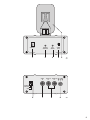
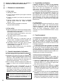
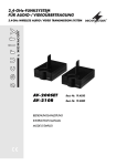
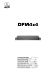
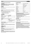
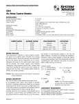
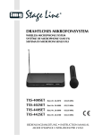
2,4-GHz-FUNKSYSTEM
10-mW-SENDER
2.4 GHz WIRELESS TRANSMISSION SYSTEM
10 mW TRANSMITTER
AV-3040TX
Best.-Nr. 19.5060
BEDIENUNGSANLEITUNG
INSTRUCTION MANUAL
MODE D’EMPLOI
ISTRUZIONI PER L’USO
®
®
AV-3040TX
D
A
CH
GB
ACHTUNG!
Änderung der Bedienungsanleitung
ATTENTION!
Modification of the instruction manual
Das Kapitel 3.1 „Zulassung“ in der Bedienungsanleitung ist nicht mehr gültig. Der aktuelle Text
für dieses Kapitel lautet wie folgt:
The chapter 3.1 “Approval” in the instruction
manual is no longer valid; the current text of this
chapter reads as follows:
Konformität und Zulassung
Hiermit erklärt MONACOR INTERNATIONAL,
dass sich der Sender in Übereinstimmung mit
den grundlegenden Anforderungen und den
übrigen einschlägigen Bestimmungen der Richtlinie 1995/5/EG befindet. Die Konformitätserklärung kann im Internet über die Homepage von
MONACOR INTERNATIONAL abgerufen werden (www.monacor.com).
Der Sender ist für den Betrieb in den EU- und
EFTA-Staaten allgemein zugelassen und anmelde- und gebührenfrei.
Conformity and Approval
Herewith, MONACOR INTERNATIONAL declare
that the transmitter is in accordance with the
basic requirements and the other relevant regulations of the directive 1995/5/EC. The declaration of conformity can be found in the Internet via
the MONACOR INTERNATIONAL home page
(www.monacor.com).
The transmitter is licence-free and generally
approved for operation in EU and EFTA countries.
Bewahren Sie dieses Beiblatt immer zusammen mit der Bedienungsanleitung auf.
Always keep this supplementary sheet together with the instruction manual.
DEUTSCH
Bevor Sie einschalten …
ENGLISH
Before switching on …
Wir wünschen Ihnen viel Spaß mit Ihrem neuen
Gerät von MONACOR. Bitte lesen Sie diese
Bedienungsanleitung vor dem Betrieb gründlich
durch. Nur so lernen Sie alle Funktionsmöglichkeiten kennen, vermeiden Fehlbedienungen
und schützen sich und Ihr Gerät vor eventuellen
Schäden durch unsachgemäßen Gebrauch.
Heben Sie die Anleitung für ein späteres Nachlesen auf.
Der deutsche Text beginnt auf der Seite 6.
FRANÇAIS
Avant toute installation …
ITALIANO
We wish you much pleasure with your new
MONACOR unit. Please read these operating
instructions carefully prior to operating the unit.
Thus, you will get to know all functions of the
unit, operating errors will be prevented, and
yourself and the unit will be protected against
any damage caused by improper use. Please
keep the operating instructions for later use.
The English text starts on page 8.
Prima di accendere …
Nous vous souhaitons beaucoup de plaisir à utiliser cet appareil MONACOR. Lisez ce mode
d'emploi entièrement avant toute utilisation.
Uniquement ainsi, vous pourrez apprendre l’ensemble des possibilités de fonctionnement de
l’appareil, éviter toute manipulation erronée et
vous protéger, ainsi que l’appareil, de dommages éventuels engendrés par une utilisation
inadaptée. Conservez la notice pour pouvoir
vous y reporter ultérieurement.
La version française se trouve page 10.
Vi auguriamo buon divertimento con il vostro
nuovo apparecchio di MONACOR. Leggete
attentamente le istruzioni prima di mettere in
funzione l'apparecchio. Solo così potete conoscere tutte le funzionalità, evitare comandi sbagliati e proteggere voi stessi e l'apparecchio da
eventuali danni in seguito ad un uso improprio.
Conservate le istruzioni per poterle consultare
anche in futuro.
Il testo italiano inizia a pagina 12.
3
4
channel
channel
selection
test
switch
audio
level
1
2
3
4
video
in
audio A
in
5
➀
audio B DC 7-30V
in
switching
channel in
GND
6
7
8
9
➁
5
DEUTSCH
Bitte klappen Sie die Seite 5 heraus. Sie sehen
dann immer die beschriebenen Bedienelemente
und Anschlüsse.
1
Übersicht der Bedienelemente und
Anschlüsse
1.1 Frontseite
1 Kanalanzeige
2 Taste „channel selection“ zur Einstellung des
Empfangskanals 1 – 5
3 Taste „test switch“ zum Testen des Schaltkanals
4 Regler „audio level“ zum Einstellen der Empfindlichkeit für die Audioeingänge (8);
Regelbereich 500 mV – 10 V
5 hochklapp- und drehbare Sendeantenne
(nicht verkratzen)
1.2 Rückseite
6 2polige Klemmleiste für den Schaltkanaleingang
zum Anschluss z. B. eines Bewegungssensors mit
NO-Kontakt
Zum Aktivieren des Schaltkanals die beiden Anschlüsse kurzschließen.
7 Cinch-Buchse „video in“ für den Videoeingang;
1 Vss/75 Ω
8 Cinch-Buchsen „audio A in“ und „audio B in“ für
die Audioeingänge;
Eingangsempfindlichkeit mit dem Regler „audio
level“ (4) von 500 mV bis 10 V einstellbar
9 Kleinspannungsbuchse „DC 7-30V“ für die Spannungsversorgung mit 7 – 30 V /max. 130 mA;
Mittelkontakt = Pluspol;
benötigter Kleinspannungsstecker 5,5/2,1 mm
(Außen-/Innendurchmesser)
2
Wichtige Hinweise für den Gebrauch
Der Sender entspricht allen erforderlichen Richtlinien
der EU und ist deshalb mit
gekennzeichnet.
● Verwenden Sie den Sender nur im Innenbereich.
Schützen Sie ihn vor Tropf- und Spritzwasser,
hoher Luftfeuchtigkeit und extremen Temperaturen
(zulässiger Einsatztemperaturbereich -10 °C bis
+55 °C).
● Verwenden Sie für die Reinigung nur ein trockenes,
weiches Tuch, auf keinen Fall Chemikalien oder
Wasser.
● Wird der Sender zweckentfremdet, nicht richtig angeschlossen, falsch bedient oder nicht fachgerecht
repariert, kann keine Haftung für daraus resultierende Sach- oder Personenschäden und keine
Garantie für den Sender übernommen werden.
Soll der Sender endgültig aus dem Betrieb
genommen werden, übergeben Sie ihn zur
umweltgerechten Entsorgung einem örtlichen Recyclingbetrieb.
6
3
Einsatzmöglichkeiten
Der Sender AV-3040TX dient in Verbindung mit einem
2,4-GHz-Empfänger der Serie „AV-3...R“ von
MONACOR zur drahtlosen Übertragung von Videound Audiosignalen. Zum Aufbau einer drahtlosen
Video-Überwachungsanlage werden zusätzlich nur
noch eine Videokamera und ein Monitor benötigt.
Die Übertragungsreichweite hängt stark von den
örtlichen Gegebenheiten ab. Bei Sichtverbindung
zwischen Sender und Empfänger kann sie bis zu
500 m betragen. In Gebäuden reduziert sich die
Reichweite jedoch durch die Wände und Decken je
nach deren Beschaffenheit auf ca. 50 m. Durch die
Verwendung einer gewinnbringenden Antenne am
Empfänger kann die Reichweite jedoch um ein Mehrfaches erhöht werden.
3.1 Zulassung
Die Zulassung für den Sender AV-3040TX ist nach
der R + TTE-Richtlinie (Radio and Telecommunication Technical Equipment) in den Staaten der Europäischen Union gültig. Für den Betrieb in Staaten
außerhalb der EU fragen Sie bitte Ihren Fachhändler
oder die MONACOR-Niederlassung des entsprechenden Landes.
4
Inbetriebnahme
4.1 Platzierung von Sender und Empfänger
Die beste Empfangsqualität erhält man, wenn die
Antenne des Senders und des Empfängers parallel
zueinander stehen. Nach der Inbetriebnahme am
Sender dazu die Antenne (5) senkrecht hochklappen
und auf optimalen Empfang drehen.
Erfahrungen aus der Praxis haben gezeigt, dass
ein optimaler Empfang bei einer Aufstellung in einer
Höhe von mindestens 1,5 bis 2 m über dem Boden
erreicht wird. Vor der endgültigen Montage sollte ein
Probebetrieb erfolgen, da bereits durch Verschieben
von Sender und Empfänger um nur einige Zentimeter
sich die Übertragungsqualität erheblich ändern kann.
4.2 Geräte anschließen
Vor dem Anschließen von Geräten bzw. Ändern bestehender Anschlüsse den Sender und alle anderen
Geräte der Überwachungsanlage ausschalten.
1) Das Videosignal der Kamera bzw. der Signalquelle über ein 75-Ω-Koaxialkabel auf die Cinchbuchse „video in“ (7) geben. Der Pegel des Videosignals muss normgerecht 1 Vss betragen.
2) Zur Tonübertragung das Audiosignal der Kamera
bzw. der Signalquelle über ein abgeschirmtes
Audiokabel auf die Buchse „audio A in“ geben und
bei einer Stereoübertragung zusätzlich auf die
Buchse „audio B in“ (8).
3) Ist der verwendete Empfänger mit einem Schaltkanal ausgestattet, lässt sich ein an ihm angeschlossener optischer bzw. akustischer Signalgeber hierüber aktivieren oder ein anderes Zusatzgerät (z. B. Videorecorder, um eine Aufnahme
4.3 Einstellungen vornehmen
4.3.1 Kanalwahl
Die Funkübertragung erfolgt im 2,4-GHz-Bereich, der
vom Hersteller in fünf Kanäle mit einem Abstand von
14 MHz aufgeteilt wurde. Maximal können gleichzeitig drei Kanäle benutzt werden (Kanal 1, 3 und 5),
weil zwei direkt nebeneinander liegende Kanäle sich
stören. Es wird folgende Kanalwahl empfohlen:
bei zwei Sendern: Kanal 1 und 5
bei drei Sendern: Kanal 1, 3 und 5
Den Sendekanal mit der Taste „channel selection“ (2)
einstellen. Dieser wird in der Kanalanzeige (1) angegeben.
5
Technische Daten
Sendefrequenz: . . . . . . . . Kanal 1
Kanal 2
Kanal 3
Kanal 4
Kanal 5
2,4145 GHz
2,4285 GHz
2,4425 GHz
2,4565 GHz
2,4705 GHz
DEUTSCH
automatisch zu starten). Am Sender wird der
Schaltkanal durch Kurzschließen der Klemmanschlüsse (6) aktiviert. An diese z. B. einen Bewegungssensor mit Schließkontakt (NO) anschließen.
Zum Testen des Schaltkanals nach der Inbetriebnahme die Taste „test switch“ (3) betätigen.
Für die Dauer des Tastendrucks wird ein Schaltsignal gesendet, welches das am Schaltausgang
des Empfängers angeschlossene Gerät aktiviert.
4) Zur Stromversorgung wird ein stabilisiertes Netzgerät mit einer Ausgangsspannung zwischen
7 V und 30 V und einem Ausgangsstrom von
mindestens 150 mA benötigt, z. B. PS-500ST von
MONACOR. Bei Netzgeräten mit variabler Ausgangsspannung diese zwischen 7 V und 30 V einstellen. Das Netzgerät über einen Kleinspannungsstecker 5,5/2,1 mm (Außen-/Innendurchmesser) an die Buchse „DC 7-30V“ (9)
anschließen. Dabei unbedingt die Polung beachten: den Pluspol an den Innenkontakt des
Steckers anlegen. Nach dem Anschluss der Versorgungsspannung ist der Sender betriebsbereit
und die Kanalanzeige (1) leuchtet.
Sendeleistung: . . . . . . . . . 10 mW (EIRP)
Antenne: . . . . . . . . . . . . . Platinenantenne
Reichweite
bei Sichtverbindung: . . bis 500 m
in Gebäuden: . . . . . . . . bis 50 m
Video
Eingangspegel: . . . . . . 1 Vss ±0,1 Vss an 75 Ω
Bandbreite: . . . . . . . . . 30 Hz – 5 MHz
Audio
Tonträgerfrequenz
Ton A: . . . . . . . . . . . .
Ton B: . . . . . . . . . . .
Eingangspegel: . . . . . .
Bandbreite: . . . . . . . . .
6,5 MHz
5,5 MHz
500 mV – 10 V an 10 kΩ
15 Hz – 15 kHz
Modulation Audio/Video: . frequenzmoduliert F3F
Schaltkanal
Trägerfrequenz: . . . . . . 32 kHz
Eingang: . . . . . . . . . . . für Schließer
(NO-Kontakt)
Stromversorgung: . . . . . . 7 – 30 V /max. 130 mA
Einsatztemperatur: . . . . . -10 °C bis +55 °C
Abmessungen
ohne Antenne (B x H x T): 105 x 48 x 100 mm
Gewicht: . . . . . . . . . . . . . . 470 g
Änderungen vorbehalten.
4.3.2 Audiopegel einstellen
Die Eingangsempfindlichkeit der Eingänge „audio A
in“ und „audio B in“ (8) lässt sich mit dem Regler
„audio level“ (4) von 500 mV bis 10 V einstellen. Das
Tonsignal am Empfänger bzw. Monitor darf weder
verzerren, dann den Regler entsprechend zurückdrehen, noch verrauscht sein, dann den Regler entsprechend weiter aufdrehen.
Diese Bedienungsanleitung ist urheberrechtlich für MONACOR ® INTERNATIONAL GmbH & Co. KG
geschützt. Eine Reproduktion für eigene kommerzielle Zwecke – auch auszugsweise – ist untersagt.
7
ENGLISH
Please unfold page 5. Then you can always see the
operating elements and connections described.
1
Operating Elements and Connections
1.1 Front panel
1 Channel display
2 Button “channel selection” for adjusting the receiving channels 1 – 5
3 Button “test switch” for testing the control channel
4 Control “audio level” for adjusting the sensitivity of
the audio inputs (8);
control range 500 mV – 10 V
5 Transmitting antenna, to be folded out and turned
(antenna must not be scratched)
1.2 Rear panel
6 2-pole terminal strip for the control channel input
for connecting e. g. a motion detector with NO
(normally open) contact
To activate the control channel, short-circuit the
two connections.
7 Phono jack “video in” for the video input;
1 Vpp/75 Ω
8 Phono jacks “audio A in” and “audio B in” for the
audio inputs;
input sensitivity adjustable from 500 mV to 10 V
with the control “audio level” (4)
9 Low voltage jack “DC 7-30 V” for the power supply
with 7 – 30 V /max. 130 mA;
centre contact = positive pole;
required low voltage plug 5.5/2.1 mm (outside/
inside diameter)
2
Important Notes
The transmitter corresponds to all required directives
of the EU and is therefore marked with .
● The transmitter is suitable for indoor use only. Protect it against dripping water and splash water, high
air humidity, and extreme temperatures (admissible
ambient temperature range -10 °C to +55 °C).
● For cleaning only use a dry, soft cloth, by no means
chemicals or water.
● No guarantee claims for the transmitter and no liability for any resulting personal damage or material
damage will be accepted if the transmitter is used
for other purposes than originally intended, if it is
not correctly connected or operated or not repaired
in an expert way.
If the transmitter is to be put out of operation
definitively, take it to a local recycling plant
for a disposal which is not harmful to the
environment.
8
3
Applications
In combination with a 2.4 GHz receiver of the
MONACOR “AV-3...R” series, the transmitter AV-3040
TX serves for wireless transmission of video and
audio signals. For setting up a wireless video surveillance system, merely a video camera and a monitor
are additionally required.
The transmission range largely depends on the
local conditions. Without any obstacles between the
transmitter and the receiver, the maximum range is
500 m. However, in buildings it is reduced to approx.
50 m by walls and ceilings, depending on their condition. By using an antenna with gain at the receiver,
the range can be increased many times over.
3.1 Approval
According to the R+TTE directive (Radio and Telecommunication Technical Equipment), the approval
for the transmitter AV-3040TX is valid in the countries
of the European Union. For operation in countries
outside the EU, please contact your retailer or the
MONACOR subsidiary in the country where this unit
will be operated.
4
Operation
4.1 Placing the transmitter and the receiver
The highest reception quality is achieved when placing the antennas of the transmitter and the receiver in
parallel. For this purpose, after setting the unit into
operation, unfold the antenna (5) vertically and turn it
to optimum reception.
Practical experience has shown that an optimum
reception is achieved when placing the units at a
height of minimum 1.5 m to 2 m above the ground.
Prior to final mounting, a trial run is recommended as
the transmission quality can be substantially changed
by displacing the transmitter and the receiver by a few
centimetres only.
4.2 Connecting units
Prior to connecting any units or to changing any existing connections, switch off the transmitter and all
other units of the surveillance system.
1) Feed the video signal of the camera or the signal
source via a 75 Ω coaxial cable to the phono jack
“video in” (7). The level of the video signal must be
1 Vpp according to standard.
2) For audio transmission, feed the audio signal of
the camera or the signal source via a shielded
audio cable to the jack “audio A in” and, in case of
stereo transmission, additionally to the jack “audio
B in” (8).
3) If the receiver used is provided with a control
channel, it is possible to activate an optical or
acoustic signal device or another additional unit
connected to the receiver via this channel (e. g.
5
4.3 Adjustments
Control channel
Carrier frequency: . . . . 32 kHz
Input: . . . . . . . . . . . . . . for NO (normally open)
contact
4.3.1 Channel selection
The wireless transmission is made in the 2.4 GHz
range which has been divided by the manufacturer
into five channels with a distance of 14 MHz. As a
maximum, three channels can be used simultaneously (channels 1, 3, and 5) as two adjacent channels will interfere with each other. The following channel selection is recommended:
for two transmitters: channels 1 and 5
for three transmitters: channels 1, 3, and 5
Specifications
Transmitting frequency: . . channel 1
channel 2
channel 3
channel 4
channel 5
2.4145 GHz
2.4285 GHz
2.4425 GHz
2.4565 GHz
2.4705 GHz
ENGLISH
video recorder for automatic start of a recording).
On the transmitter, the control channel is activated
by short-circuiting the terminals (6). Connect e. g.
a motion detector with NO (normally open) contact
to these terminals.
For testing the control channel after setting the
transmitter into operation, actuate the button “test
switch” (3). As long as the button is actuated, a
control signal is transmitted which will activate the
unit connected to the control output of the receiver.
4) For power supply, a regulated power supply unit
with an output voltage between 7 V and 30 V
and an output current of at least 150 mA is required, e. g. MONACOR PS-500ST. In case of
power supply units with variable output voltage,
adjust a value between 7 V and 30 V. Connect the
power supply unit via a low voltage plug 5.5/
2.1 mm (outside/inside diameter) to the jack “DC
7-30 V” (9). Always observe the correct polarity:
connect the positive pole to the inner contact of the
plug. After the supply voltage has been applied,
the transmitter is ready for operation and the channel display (1) lights up.
Transmitting power: . . . . . 10 mW (EIRP)
Antenna: . . . . . . . . . . . . . PCB antenna
Operating range
without any obstacles: . 500 m max.
in buildings: . . . . . . . . . 50 m max.
Video
Input level: . . . . . . . . . . 1 Vpp ±0.1 Vpp at 75 Ω
Bandwidth: . . . . . . . . . . 30 Hz – 5 MHz
Audio
Audio carrier frequency
Audio A . . . . . . . . . .
Audio B: . . . . . . . . . .
Input level: . . . . . . . . . .
Bandwidth: . . . . . . . . . .
6.5 MHz
5.5 MHz
500 mV – 10 V at 10 kΩ
15 Hz – 15 kHz
Modulation audio/video: . frequency modulated
F3F
Power supply: . . . . . . . . . 7 – 30 V /max. 130 mA
Ambient temperature: . . . -10 °C to +55 °C
Dimensions w/o antenna
(W x H x D): . . . . . . . . . . . 105 x 48 x 100 mm
Weight: . . . . . . . . . . . . . . . 470 g
Subject to technical modification.
Adjust the transmission channel with the button
“channel selection” (2). The selected channel will then
appear on the channel display (1).
4.3.2 Adjusting the audio level
The input sensitivity of the inputs “audio A in” and
“audio B in” (8) can be adjusted from 500 mV to 10 V
with the control “audio level” (4). The audio signal at
the receiver or the monitor must neither be distorted
(in this case turn back the control correspondingly)
nor noisy (in this case advance the control correspondingly).
All rights reserved by MONACOR ® INTERNATIONAL GmbH & Co. KG. No part of this instruction manual may
be reproduced in any form or by any means for any commercial use.
9
FRANÇAIS
Ouvrez le présent livret page 5 de manière à
visualiser les éléments et branchements.
1
Eléments et branchements
1.1 Face avant
1 Affichage du canal
2 Touche “channel selection” pour régler le canal de
réception 1 à 5
3 Touche “test switch” pour tester le canal de commutation
4 Réglage “audio level” pour régler la sensibilité
pour les entrées audio (8) : plage de réglage
500 mV – 10 V
5 Antenne émettrice dépliable et tournante
(ne pas érafler l’antenne)
1.2 Face arrière
6 Barrette 2 pôles pour l’entrée du canal de commutation pour brancher par exemple un détecteur de
mouvements avec contact NO
Pour activer le canal de commutation, court-circuitez les deux branchements.
7 Prise RCA “video in” pour l’entrée vidéo :
1 Vcc/75 Ω
8 Prises RCA “audio A in” et “audio B in” pour les
entrées audio ; sensibilité d’entrée réglable avec
le réglage “audio level” (4) de 500 mV à 10 V
9 Prise basse tension “DC 7-30V” pour la tension
d’alimentation avec 7 – 30 V /130 mA max ;
contact médian = pôle plus
Une fiche basse tension 5,5/2,1 mm (diamètre
extérieur/intérieur) est nécessaire.
2
Conseils importants d’utilisation
L’émetteur répond à toutes les directives nécessaires
de l’Union Européenne et porte donc le symbole .
●
L’émetteur n’est conçu que pour une utilisation en
intérieur. Protégez-le des projections d’eau et éclaboussures, d’une humidité élevée de l’air et de
températures extrêmes (plage de température de
fonctionnement autorisée : -10 °C à +55 °C).
●
Pour le nettoyer, utilisez uniquement un chiffon sec
et doux, en aucun cas de produits chimiques ou
d’eau.
●
Nous déclinons toute responsabilité en cas de
dommages corporels ou matériels résultants si
l’émetteur est utilisé dans un but autre que celui
pour lequel il a été conçu, s’il n’est pas correctement branché, utilisé ou réparé par une personne
habilitée; en outre, la garantie deviendrait caduque.
Lorsque l’émetteur est définitivement retiré
du service, vous devez le déposer dans une
usine de recyclage de proximité pour contribuer à son élimination non polluante.
10
3
Possibilités d’utilisation
L’émetteur AV-3040TX, combiné à un récepteur
2,4 GHz de la série “AV-3…R” de MONACOR sert
pour une transmission sans fil de signaux vidéo et
audio. Pour créer une installation de surveillance
vidéo sans fil, une caméra vidéo et un moniteur uniquement sont, en plus, nécessaires.
La portée de transmission dépend grandement de
la configuration des lieux d’utilisation. Lorsqu’il n’y a
pas d’obstacle entre l’émetteur et le récepteur, elle
peut atteindre 500 m. Dans des bâtiments, elle diminue jusqu’à 50 m environ selon la composition des
murs et plafonds. Si vous utilisez une antenne avec
gain sur le récepteur, la portée peut être augmentée
plusieurs fois.
3.1 Autorisation
L’autorisation pour l’émetteur AV-3040TX est, selon la
directive R+TTE (Radio and Telecommunication
Technical Equipment), valable dans les pays de
l’Union Européenne. Pour un fonctionnement en
dehors de l’Union Européenne, contactez votre
revendeur ou la succursale MONACOR dans le pays
concerné.
4
Fonctionnement
4.1 Placement de l’émetteur et du récepteur
La qualité de réception est optimale lorsque les
antennes de l’émetteur et du récepteur sont parallèles. Après la mise en fonction, sur l’émetteur,
déployez l’antenne (5) à la verticale et tournez-la vers
la réception optimale.
L’expérience montre que la réception est optimale
pour un positionnement des appareils à une hauteur
de 1,5 m à 2 m au moins au-dessus du sol. Avant le
montage définitif, il est conseillé d’effectuer un test
car un déplacement de l’émetteur et du récepteur de
quelques centimètres uniquement peut modifier considérablement la qualité de transmission.
4.2 Branchements des appareils
Avant de brancher les appareils ou de modifier les
branchements existants, veillez à éteindre l’émetteur
et tous les appareils de l’installation de surveillance.
1) Appliquez le signal vidéo de la caméra ou de la
source de signal via un câble coaxial 75 Ω à la
prise RCA “video in” (7). Le niveau du signal vidéo
doit, selon la norme, être de 1 Vcc.
2) Pour la transmission audio, appliquez le signal
audio de la caméra ou de la source de signal via
un cordon audio blindé à la prise “audio A in” et
pour une transmission stéréo, en plus à la prise
“audio B in” (8).
3) Si le récepteur utilisé est doté d’un canal de commutation, on peut activer un avertisseur optique
ou acoustique ou un appareil supplémentaire (par
exemple magnétoscope pour démarrer automatiquement un enregistrement) branché à ce canal.
Le canal de commutation est activé, côté émet-
4.4 Réglages
4.4.1 Sélection des canaux
La transmission sans fil s’effectue dans la plage
2,4 GHz, divisée par le fabricant en cinq canaux avec
une distance de 14 MHz. On peut utiliser simultanément trois canaux (canal 1, 3 et 5) au plus car deux
canaux directement consécutifs se perturbent. La
sélection suivante de canaux est recommandée :
Pour deux émetteurs : canaux 1 et 5
Pour trois émetteurs : canaux 1, 3 et 5
Réglez le canal d’émission avec la touche “channel
selection” (2), il est indiqué sur l’affichage de canal (1).
4.4.2 Réglage du niveau audio
La sensibilité d’entrée des entrées “audio A in” et
“audio B in” (8) se règle avec le réglage “audio level”
(4) de 500 mV à 10 V. Le signal audio sur le récepteur
ou le moniteur ne doit pas être distordu, tournez,
dans ce cas, le réglage en arrière, ni bruyant – ouvrez
le réglage en conséquence.
5
Caractéristiques techniques
Fréquence d’émission : . . canal 1
canal 2
canal 3
canal 4
canal 5
2,4145 GHz
2,4285 GHz
2,4425 GHz
2,4565 GHz
2,4705 GHz
FRANÇAIS
teur, en court-circuitant les bornes (6). On peut
relier par exemple à ces bornes un détecteur de
mouvements avec contact de fermeture (NO).
Pour tester le canal de commutation, après la
mise en fonction, activez la touche “test switch”
(3). Tant que la touche est activée, un signal de
contrôle est émis, il active l’appareil relié à la sortie de commutation du récepteur.
4) Pour l’alimentation, une alimentation stabilisée
avec une tension de sortie entre 7 V et 30 V et
un courant de sortie de 150 mA au moins est
nécessaire, p. ex. PS-500ST de MONACOR. Pour
des alimentations avec une tension de sortie
variable, réglez-la entre 7 V et 30 V. Reliez l’alimentation via une fiche basse tension 5,5/2,1 mm
(extérieur/intérieur) à la prise “DC 7-30V” (9).
Veillez à respecter la polarité : le pôle plus est au
contact intérieur de la fiche. L’émetteur est prêt à
fonctionner une fois la tension de fonctionnement
appliquée, l’affichage de canal (1) brille.
Puissance émission : . . . . 10 mW (EIRP)
Antenne : . . . . . . . . . . . . . antenne platine
Portée
en l’absence
d’obstacle : . . . . . . . . . jusqu’à 500 m
en intérieur : . . . . . . . . . jusqu’à 50 m
Vidéo
Niveau d’entrée : . . . . . 1 Vcc ±0,1 Vcc sous 75 Ω
Largeur de bande : . . . 30 Hz – 5 MHz
Audio
Fréquence porteuse audio
Son A : . . . . . . . . . . . 6,5 MHz
Son B : . . . . . . . . . . . 5,5 MHz
Niveau d’entrée : . . . . . 500 mV – 10 V sous 10 kΩ
Largeur de bande : . . . 15 Hz – 15 kHz
Modulation Audio/Vidéo : modulation de fréquence
F3F
Canal de commutation
Fréquence porteuse : . 32 kHz
Entrée : . . . . . . . . . . . . pour fermeture
(contact NO)
Alimentation : . . . . . . . . . . 7 – 30 V
/130 mA max.
Température fonc. : . . . . . -10 °C jusqu’à +55 °C
Dimensions
sans antenne (l x h x p) : . 105 x 48 x 100 mm
Poids : . . . . . . . . . . . . . . . 470 g
Tout droit de modification réservé.
Notice d’utilisation protégée par le copyright de MONACOR ® INTERNATIONAL GmbH & Co. KG. Toute reproduction même partielle à des fins commerciales est interdite.
11
ITALIANO
Vi preghiamo di aprire completamente la pagina 5.
Così vedrete sempre gli elementi di comando e i
collegamenti descritti.
1
Elementi di comando e collegamenti
1.1 Lato frontale
1 Indicazione dei canali
2 Tasto “channel selection” per impostare il canale
di ricezione 1 – 5
3 Tasto “test switch” per testare il canale di controllo
4 Regolatore “audio level” per impostare la sensibilità per gli ingressi audio (8);
range di regolazione 500 mV – 10 V
5 Antenna di ricezione alzabile e girevole
(non graffiarla)
1.2 Lato posteriore
6 Morsettiera a 2 poli per l’ingresso del canale di
controllo per il collegamento p. es. di un sensore
di movimento con contatto NA
Per attivare il canale di controllo mettere in corto i
due contatti.
7 Presa RCA “video in” per l’ingresso video;
1 Vpp/75 Ω
8 Prese RCA “audio A in” e “audio B in” per gli ingressi audio;
la sensibilità d’ingresso è impostabile con il regolatore “audio level” (4) da 500 mV fino 10 V
9 Presa per alimentazione “DC 7-30 V”
per 7 – 30 V /max. 130 mA;
contatto centrale = polo positivo;
spinotto richiesto 5,5/2,1 mm
(diametro esterno/interno)
2
Avvertenze importanti per l’uso
Il trasmettitore è conforme a tutte le direttive richieste
dell’UE e pertanto porta la sigla .
●
Usare il trasmettitore solo all’interno di locali. Proteggerlo dall’acqua gocciolante e dagli spruzzi
d’acqua, da alta umidità dell’aria e dal calore (temperatura d’impiego ammessa fra -10 °C e +55 °C).
●
Per la pulizia usare solo un panno morbido, asciutto; non impiegare in nessun caso prodotti chimici o
acqua.
●
Nel caso d’uso improprio, di collegamenti sbagliatI,
d’impiego scorretto o di riparazione non a regola
d’arte del trasmettitore, non si assume nessuna
responsabilità per eventuali danni consequenziali a
persone o a cose e non si assume nessuna garanzia per l’apparecchio.
Se si desidera eliminare il trasmettitore definitivamente, consegnarlo per lo smaltimento
ad un’istituzione locale per il riciclaggio.
12
3
Possibilità d’impiego
Il trasmettitore AV-3040TX, insieme ad un ricevitore a
2,4 GHz della serie “AV-3...R” di MONACOR serve
per la trasmissione wireless di segnali video e audio.
Per creare un impianto senza fili di sorveglianza video
bastano in aggiunta una telecamera e un monitor.
La portata di trasmissione dipende fortemente
dalle condizioni locali e dall’antenna di ricezione
impiegata. Se non ci sono ostacoli fra trasmettitore e
ricevitore, può arrivare fino a 500 m. Negli edifici, la
portata è ridotta per via delle pareti e dei soffitti, a
seconda delle loro caratteristiche, a 50 m ca. Impiegando un’antenna con guadagno sul ricevitore, la
portata può essere aumentata più volte.
3.1 Omologazione
Secondo la direttiva R+TTE (Radio and Telecommunication Technical Equipment), l’omologazione del
trasmettitore AV-3040TX è valida negli stati
dell’Unione Europea. Per l’impiego in stati extracomunitari occorre informarsi presso il rivenditore o la
rispettiva filiale MONACOR.
4
Messa in funzione
4.1 Posizionamento di trasmettitore e ricevitore
La migliore qualità di ricezione si ottiene quando le
antenne del trasmettitore e del ricevitore sono sistemate in modo parallelo. Dopo la messa in funzione
sul trasmettitore, alzare l’antenna (5) in senso verticale e girarla per una ricezione ottimale.
L’esperienza pratica ha dimostrato che si ottiene
una ricezione ottimale posizionando gli apparecchi ad
un’altezza di non meno di 1,5 m a 2 m dal pavimento.
Prima del montaggio definitivo conviene fare delle
prove, perché uno spostamento del trasmettitore e
del ricevitore anche di pochi centimetri può modificare notevolmente la qualità di trasmissione.
4.2 Collegare gli apparecchi
Prima di collegare degli apparecchi o modificare dei
collegamenti esistenti occorre spegnere il trasmettitore e tutti gli altri apparecchi dell’impianto di sorveglianza
1) Portare il segnale video della telecamera o della
sorgente dei segnali per mezzo di un cavo coassiale 75 Ω sulla presa RCA “video in” (7). Il livello
del segnale video deve essere 1 Vpp come da
norma.
2) Per la trasmissione audio, portare il segnale
audio della telecamera o della sorgente sulla
presa RCA “audio A in” servendosi di un cavo
schermato e, nel caso di una trasmissione stereo,
in più sulla presa RCA “audio B in” (8).
3) Se il ricevitore usato dispone di un canale di controllo, è possibile attivare con questo un segnalatore ottico o acustico collegato oppure un altro dispositivo (p. es. un videoregistratore per avviare
automaticamente una registrazione). Sul lato del
trasmettitore, il canale di controllo viene attivato
4.3 Effettuare le impostazioni
5
Dati tecnici
Frequenza di trasmissione: Canale 1
Canale 2
Canale 3
Canale 4
Canale 5
2,4145 GHz
2,4285 GHz
2,4425 GHz
2,4565 GHz
2,4705 GHz
ITALIANO
mettendo in corto i morsetti (6). Collegare con
questi morsetti p. es. un segnalatore di movimento
con contatto di lavoro (NA).
Per testare il canale di controllo azionare, dopo
la messa in funzione, il tasto “test switch” (3). Per
la durata della pressione del tasto viene inviato un
segnale sonoro che attiva il dispositivo collegato
con il canale di controllo del ricevitore.
4) Per l’alimentazione è richiesto un alimentatore
stabilizzato con tensione d’uscita fra 7 V
e
30 V e con corrente d’uscita di 150 mA min.,
p. es. PS-500ST di MONACOR. In caso di alimentatori con tensione d’uscita variabile impostare la
tensione fra 7 V e 30 V. Collegare l’alimentatore
con la presa “DC 7-30V” (9) servendosi di uno
spinotto 5,5/2,1 mm (diametro esterno/interno).
Rispettare assolutamente la corretta polarità: il
polo positivo al contatto interno dello spinotto.
Dopo aver applicato al tensione d’esercizio, il trasmettitore è acceso e la spia interna di funzionamento (1) rimane accesa.
Potenza di trasmissione: . 10 mW (EIRP)
Antenna: . . . . . . . . . . . . . antenna sul circuito
stampato
Portata
in linea diretta
senza ostacoli: . . . . . . . fino a 500 m
in edifici: . . . . . . . . . . . . fino a 50 m
Video
Livello d’ingresso: . . . . 1 Vpp ±0,1 Vpp con 75 Ω
Banda passante: . . . . . 30 Hz – 5 MHz
Audio
Frequenza della portante
Tono A: . . . . . . . . . . . 6,5 MHz
Tono B: . . . . . . . . . . 5,5 MHz
Livello d’ingresso: . . . . 500 mV – 10 V con 10 kΩ
Banda passante: . . . . . 15 Hz – 15 kHz
4.3.1 Scelta dei canali
La trasmissione wireless avviene nel settore dei
2,4 GHz, suddiviso dal produttore in cinque canali
distanti di 14 MHz gli uni dagli altri. Si possono usare
contemporaneamente al massimo tre canali (canali 1,
3 e 5), perché due canali adiacenti creerebbero delle
interferenze. È consigliabile la seguente scelta dei
canali:
con due trasmettitori: canali 1 e 5
con tre trasmettitori: canali 1, 3 e 5
Modulazione Audio/Video: modulazione di
frequenza F3F
Impostare il canale di trasmissione con il tasto “channel selection” (2). Il canale selzionato viene indicato
sul display (1).
Peso: . . . . . . . . . . . . . . . . 470 g
Canale di controllo
Frequenza portante: . . 32 kHz
Ingresso: . . . . . . . . . . . per contatto di lavoro
(NA)
Alimentazione: . . . . . . . . . 7 – 30 V
/130 mA max.
Temperatura d’esercizio: . -10 °C a +55 °C
Dimensioni
senza antenna (l x h x p): 105 x 48 x 100 mm
Con riserva di modifiche tecniche.
4.3.2 Impostare il livello audio
La sensibilità degli ingressi “audio A in” e “audio B in”
(8) può essere impostata con il regolatore “audio
level” (4) da 500 mV fino a 10 V. Il segnale audio sul
ricevitore o monitor non deve essere distorto (allora
abbassare il regolatore) e non deve presentare un
fruscio (in questo caso aprire di più il regolatore).
La MONACOR ® INTERNATIONAL GmbH & Co. KG si riserva ogni diritto di elaborazione in qualsiasi forma
delle presenti istruzioni per l’uso. La riproduzione – anche parziale – per propri scopi commerciali è vietata.
13
®
Copyright © by MONACOR INTERNATIONAL GmbH & Co. KG, Bremen, Germany. All rights reserved. A-0058.98.02.11.2006