1
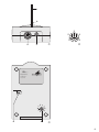
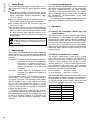
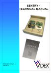
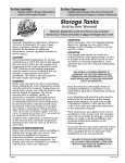
2,4-GHz-FUNKSYSTEM
FÜR AUDIO-/ VIDEOÜBERTRAGUNG
2.4 GHz WIRELESS AUDIO / VIDEO TRANSMISSION SYSTEM
AV-200SET
AV-210R
BEDIENUNGSANLEITUNG
INSTRUCTION MANUAL
MODE D’EMPLOI
Best.-Nr. 19.4030
Best.-Nr. 19.4080
®
DEUTSCH
ENGLISH
Before switching on …
FRANÇAIS
Bevor Sie einschalten …
Wir wünschen Ihnen viel Spaß mit Ihrem neuen
Gerät von MONACOR. Bitte lesen Sie diese
Bedienungsanleitung vor dem Betrieb gründlich
durch. Nur so lernen Sie alle Funktionsmöglichkeiten kennen, vermeiden Fehlbedienungen
und schützen sich und Ihr Gerät vor eventuellen
Schäden durch unsachgemäßen Gebrauch.
Heben Sie die Anleitung für ein späteres Nachlesen auf.
Der deutsche Text beginnt auf der Seite 6.
We wish you much pleasure with your new
MONACOR unit. Please read these operating
instructions carefully prior to operating the unit.
Thus, you will get to know all functions of the
unit, operating errors will be prevented, and
yourself and the unit will be protected against
any damage caused by improper use. Please
keep the operating instructions for later use.
The English text starts on page 9.
Avant toute installation …
Nous vous souhaitons beaucoup de plaisir à utiliser cet appareil MONACOR. Lisez ce mode
d'emploi entièrement avant toute utilisation.
Uniquement ainsi, vous pourrez apprendre l’ensemble des possibilités de fonctionnement de
l’appareil, éviter toute manipulation erronée et
vous protéger, ainsi que l’appareil, de dommages éventuels engendrés par une utilisation
inadaptée. Conservez la notice pour pouvoir
vous y reporter ultérieurement.
La version française se trouve page 12.
3
4
1
2
3
2
1
3
➀
4
4
6
5
➁
AV-...
®
Best.-Nr. 19...
Pegel
Empfänger
Receiver
2 3
9
5 6
0 1
4
7 8
5
6
➂
5
DEUTSCH
6
Bitte klappen Sie die Seite 5 heraus. Sie sehen
dann immer die beschriebenen Bedienelemente
und Anschlüsse.
Inhalt
1
Übersicht der Bedienelemente und
Anschlüsse . . . . . . . . . . . . . . . . . . . . . . . . . 6
1.1
Anschlüsse an der Sende- und
an der Empfangsstation . . . . . . . . . . . . . . . . 6
1.2
Geräteunterseite . . . . . . . . . . . . . . . . . . . . . . 6
2
Hinweise für den sicheren Gebrauch . . . . 7
3
Einsatzmöglichkeiten . . . . . . . . . . . . . . . . . 7
3.1
Konformität und Zulassung . . . . . . . . . . . . . . 7
4
Inbetriebnahme . . . . . . . . . . . . . . . . . . . . . . 7
4.1
Platzierung der Sende- und der Empfangsstation . . . . . . . . . . . . . . . . . . . . . . . . . . . . . . 7
4.2
Übertragungskanal einstellen . . . . . . . . . . . . 7
4.3
Geräte anschließen . . . . . . . . . . . . . . . . . . . . 8
4.4
Audio- und Videopegel korrigieren . . . . . . . . 8
5
Technische Daten . . . . . . . . . . . . . . . . . . . . 8
1
Übersicht der Bedienelemente und
Anschlüsse
1.1 Anschlüsse an der Sende- und an der
Empfangsstation
1 Antenne (nicht verkratzen oder abbrechen)
2 Betriebsanzeige, nur an der Sendestation
3 DIN-AV-Buchse, Anschlussbelegung (Abb. 2):
1 —
2 Videosignal, 1 Vss
3 Masse
4 Audio, links
5 nur an der Empfangsstation: Ausgang Versorgungsspannung +5 V, max. 80 mA für Zusatzgeräte, z. B. HF-Modulator
6 Audio, rechts (nur bei Stereo)
4 Kleinspannungsbuchse zur Spannungsversorgung
der Sender benötigt 12 V /150 mA,
der Empfänger benötigt 8 – 10 V /320 mA;
Mittelkontakt = Pluspol;
benötigter Kleinspannungsstecker 5,5/2,1 mm
(Außen-/Innendurchmesser)
1.2 Geräteunterseite
5 Trimmregler
am Empfänger zum Korrigieren des Videopegels, wenn am Wiedergabegerät (z. B. TV-Gerät,
Überwachungsmonitor) das Bild zu hell oder zu
dunkel ist
am Sender zum Korrigieren des Audiopegels,
wenn die Tonübertragung zu leise oder verzerrt ist
6 Schalter für den Übertragungskanal;
ab Werk auf Kanal 1 eingestellt
Hinweise für den sicheren Gebrauch
Das 2,4-GHz-Funksystem entspricht allen erforderlichen Richtlinien der EU und ist deshalb mit
gekennzeichnet.
● Das System ist nur zur Verwendung im Innenbereich geeignet. Schützen Sie es vor Verschmutzung, Feuchtigkeit und extremen Temperaturen
(zulässiger Einsatztemperaturbereich -10 °C bis
+55 °C).
● Die Antenne (1) nicht abbrechen oder verkratzen.
Sie ist fest montiert. Versuchen Sie nicht, die
Antenne aus dem Gerät herauszuziehen.
● Verwenden Sie für die Reinigung nur ein trockenes,
weiches Tuch, auf keinen Fall Chemikalien oder
Wasser.
● Wird das Übertragungssystem zweckentfremdet,
nicht richtig angeschlossen, falsch bedient oder
nicht fachgerecht repariert, kann keine Haftung für
daraus resultierende Sach- oder Personenschäden
und keine Garantie für das System übernommen
werden.
Soll das System endgültig aus dem Betrieb
genommen werden, übergeben Sie es zur
umweltgerechten Entsorgung einem örtlichen Recyclingbetrieb.
3
3.1 Konformität und Zulassung
Hiermit erklärt MONACOR INTERNATIONAL, dass
sich das Funksystem AV-200SET in Übereinstimmung mit den grundlegenden Anforderungen und den
übrigen einschlägigen Bestimmungen der Richtlinie
1995/5/EG befindet. Die Konformitätserklärung kann
im Internet über die Homepage von MONACOR
INTERNATIONAL (www.monacor.com) abgerufen
werden.
Das Funksystem ist für den Betrieb in den EU- und
EFTA-Staaten allgemein zugelassen und anmeldeund gebührenfrei.
4
DEUTSCH
2
Inbetriebnahme
4.1 Platzierung der Sende- und der Empfangsstation
Die beste Empfangsqualität erhält man, wenn die
Antennen (1) der Stationen parallel zueinander stehen. Erfahrungen aus der Praxis haben gezeigt, dass
ein optimaler Empfang bei einer Aufstellung in einer
Höhe von mindestens 1,5 bis 2 m über dem Boden
erreicht wird. Vor der endgültigen Montage sollte ein
Probebetrieb erfolgen, denn durch Verschieben der
Sende- und der Empfangsstation um nur einige Zentimeter kann sich die Übertragungsqualität erheblich
ändern.
Einsatzmöglichkeiten
Das 2,4-GHz-Funksystem überträgt drahtlos TV-/
Video-Bild und Stereo-HiFi-Ton. Dazu sind die folgenden Geräte verfügbar:
AV-200SET Komplettset mit Sender und Empfänger
mit Stereoton. Zur gleichzeitigen Übertragung unterschiedlicher Signale (z. B.
Kinderzimmerüberwachung und Musikübertragung) können bis zu drei Sets
parallel genutzt werden.
AV-210R
Empfangsstation zur Erweiterung des
Komplettsets, um die Signale zu einem
zweiten Gerät zu übertragen
An die Sendestation lässt sich z. B. ein Satellitenreceiver, ein Videorecorder, eine HiFi-Anlage oder
eine Überwachungskamera anschließen. Die Sendestation überträgt die Signale zur Empfangsstation,
von wo aus sie zum Wiedergabegerät gelangen (z. B.
TV-Gerät, Videorecorder, HiFi-Verstärker oder Überwachungsmonitor). VPS- und Videotextsignale werden dabei selbstverständlich mitübertragen.
Die Übertragungsreichweite hängt stark von den
örtlichen Gegebenheiten ab. Bei Sichtverbindung
zwischen Sender und Empfänger kann sie bis zu
300 m betragen. In Gebäuden reduziert sich die
Reichweite jedoch durch die Wände und Decken je
nach deren Beschaffenheit auf ca. 30 m.
4.2 Übertragungskanal einstellen
Die Funkübertragung erfolgt im 2,4-GHz-Bereich, der
vom Hersteller in fünf Kanäle mit einem Abstand von
14 MHz aufgeteilt wurde. Maximal können gleichzeitig drei Kanäle benutzt werden (Kanal 1, 3 und 5),
weil zwei direkt nebeneinander liegende Kanäle sich
stören. Bei Betrieb mehrerer Funksysteme gleichzeitig wird folgende Kanalwahl empfohlen:
bei zwei Systemen: Kanal 1 und 5
bei drei Systemen: Kanal 1, 3 und 5
Die Sende- und die Empfangsstation müssen auf den
gleichen Kanal eingestellt sein, anderenfalls ist keine
Übertragung möglich. Vom Werk aus sind die Geräte
auf Kanal 1 eingestellt. Zum Einstellen des Kanals
den Umschalter (6) mithilfe eines Schraubendrehers
in die entsprechende Position drehen:
Position
Kanal
1
1
2
2
3
3
4
4
5
5
6 ... 0
1
7
DEUTSCH
4.3 Geräte anschließen
Zum Betrieb der Sende- und der Empfangsstation
wird zusätzlich je ein stabilisiertes Netzgerät benötigt,
z. B. PS-500ST von MONACOR.
Wichtig!
Beim Anschluss die Sende- und die Empfangsstation nicht verwechseln, sonst arbeitet das Funksystem nicht. Die Stationen unterscheiden sich äußerlich kaum. Nur die Sendestation hat eine Betriebsanzeige (2). Weiterhin lassen sich die Geräte auf der
Unterseite durch den Aufkleber mit dem Schriftzug
„Sender“ bzw. „Empfänger“ unterscheiden.
1) Die DIN-AV-Buchse (3) der Sendestation mit dem
Audio-(Video)-Ausgang der Signalquelle (z. B. HiFiAnlage, Überwachungskamera, Satellitenreceiver,
Videorecorder) verbinden. Ist an der Signalquelle
eine Scart-Buchse vorhanden, das beiliegende
Scart-Anschlusskabel verwenden und den Schalter am Scart-Stecker in die Position „IN“ stellen.
Sind an der Signalquelle Cinch-Buchsen vorhanden, das Cinch-Anschlusskabel verwenden:
Den gelben Cinch-Stecker in den Video-Ausgang
stecken, den schwarzen Cinch-Stecker in den
Ausgang des (linken) Audiokanals und bei einer
Stereoton-Übertragung den roten Cinch-Stecker
in den Ausgang des rechten Audiokanals.
2) Die DIN-AV-Buchse (3) der Empfangsstation mit
dem Audio-(Video)-Eingang des Wiedergabegerätes (z. B. HiFi-Verstärker, TV-Gerät, Überwachungsmonitor) verbinden. Ist an dem Wiedergabegerät
eine Scart-Buchse vorhanden, das beiliegende
Scart-Anschlusskabel verwenden und den Schalter am Scart-Stecker in die Position „OUT“ stellen.
Sind am Wiedergabegerät Cinch-Buchsen vorhanden, das Cinch-Anschlusskabel verwenden:
Den gelben Cinch-Stecker in den Video-Eingang
stecken, den schwarzen Cinch-Stecker in den Eingang des (linken) Audiokanals und bei einer Stereoton-Übertragung den roten Cinch-Stecker in
den Eingang des rechten Audiokanals.
Zum Anschluss der Empfangsstation an ein TVGerät ohne Scart- oder Cinch-Buchsen den HFModulator VAM-3 von MONACOR verwenden. Er
wird an die Antennenbuchse des TV-Gerätes angeschlossen.
3) An die Gleichspannungsbuchse (4) der Sendeund der Empfangsstation je ein Netzgerät anschließen. Dabei unbedingt die Polung beachten:
den Pluspol an den Innenkontakt des Steckers anlegen. An den Netzgeräten die Ausgangsspannung einstellen:
9 V für den Empfänger
12 V für den Sender
Erst nachdem alle anderen Anschlüsse ausgeführt
sind, die Netzgeräte an eine Steckdose (230 V~/
50 Hz) anschließen. Das Funksystem ist danach
betriebsbereit. Am Sender leuchtet die Betriebsanzeige (2).
4) Ist die Übertragung durch Störungen im gewählten
Kanal schlecht, sowohl die Sende- als auch die
Empfangsstation auf einen störungsfreien Kanal
umschalten.
5) Wird das System längere Zeit nicht benutzt, die
Netzgeräte aus den Steckdosen ziehen, weil diese
ständig einen geringen Strom verbrauchen.
4.4 Audio- und Videopegel korrigieren
1) Wenn am Wiedergabegerät (TV-Gerät, Überwachungsmonitor) das Bild zu hell oder zu dunkel
erscheint, mit dem Regler „Pegel“ (5) an der Empfangsstation den Videopegel korrigieren. Dazu
einen Schraubendreher zu Hilfe nehmen.
2) Wenn die Tonwiedergabe verzerrt oder zu leise ist,
mit dem Regler „Pegel“ (5) an der Sendestation
den Audiopegel korrigieren.
5
Technische Daten
Sendeleistung: . . . . . . . . . ≤ 10 mW (EIRP)
Sende-/Empfangsfrequenz: . . . . . . . . . . . . . Kanal 1
Kanal 2
Kanal 3
Kanal 4
Kanal 5
2,4145 GHz
2,4285 GHz
2,4425 GHz
2,4565 GHz
2,4705 GHz
Antenne: . . . . . . . . . . . . . Platinenantenne
Reichweite
bei Sichtverbindung: . . bis 300 m
in Gebäuden: . . . . . . . . bis 30 m
Video
Ein- bzw. Ausgang: . . . 1 Vss/75 Ω
Bandbreite: . . . . . . . . . 30 Hz bis 5 MHz
Audio
Ein- bzw. Ausgang: . . . 500 mV/10 kΩ
Bandbreite: . . . . . . . . . 15 Hz bis 16 kHz
Stromversorgung
Sender: . . . . . . . . . . . . 12 V /150 mA
Empfänger . . . . . . . . . . 8 – 10 V /320 mA
Gehäuseschutzart: . . . . . IP 30
Einsatztemperatur: . . . . . -10 °C bis +55 °C
Abmessungen (B x H x T): 80 x 35 x 130 mm
Gewicht
AV-200SET: . . . . . . . . . 450 g
AV-210R: . . . . . . . . . . . 230 g
Änderungen vorbehalten.
Diese Bedienungsanleitung ist urheberrechtlich für MONACOR ® INTERNATIONAL GmbH & Co. KG
geschützt. Eine Reproduktion für eigene kommerzielle Zwecke – auch auszugsweise – ist untersagt.
8
Contents
1
Operating Elements and Connections
1.1
Connections of the transmitter station
and the receiver station . . . . . . . . . . . . . . . . . 9
1.2
Lower side of the unit . . . . . . . . . . . . . . . . . . 9
2
Safety Notes . . . . . . . . . . . . . . . . . . . . . . . . 10
3
Applications . . . . . . . . . . . . . . . . . . . . . . . . 10
3.1
Conformity and Approval . . . . . . . . . . . . . . . 10
4
Operation . . . . . . . . . . . . . . . . . . . . . . . . . . 10
4.1
Placing the transmitter station
and the receiver station . . . . . . . . . . . . . . . . 10
4.2
Setting the transmission channel . . . . . . . . 10
4.3
Connecting the units . . . . . . . . . . . . . . . . . . 11
4.4
Readjusting the audio and video levels . . . . 11
5
Specifications . . . . . . . . . . . . . . . . . . . . . . 11
1
Operating Elements and Connections
1.1 Connections of the transmitter station and
the receiver station
ENGLISH
Please unfold page 5. Then you can always see the
operating elements and connections described.
1 Antenna (do not scratch or break off)
2 Power LED, on the transmitter station only
3 DIN AV jack, pin configuration (fig. 2):
1 —
2 video signal, 1 Vpp
3 ground
4 audio, left
5 on the receiver station only: output of control
voltage +5 V, max. 80 mA for additional units,
e. g. RF modulator
6 audio, right (for stereo only)
4 Low voltage jack for power supply
the transmitter requires 12 V /150 mA,
the receiver requires 8 – 10 V /320 mA;
centre contact = positive pole
required low voltage plug 5.5/2.1 mm (outside/inside diameter)
1.2 Lower side of the unit
5 Trimming control
on the receiver for readjusting the video level if
the picture on the reproduction unit (e. g. TV set,
surveillance monitor) is too bright or too dark
on the transmitter for readjusting the audio level
if the sound transmission is too low or distorted
6 Selector switch for the transmission channel;
factory-set to channel 1
9
ENGLISH
2
Safety Notes
The 2.4 GHz wireless system corresponds to all required directives of the EU and is therefore marked
with .
● The system is suitable for indoor use only. Protect
it against impurities, humidity, and extreme temperatures (admissible ambient temperature range
-10 °C to +55 °C).
● Do not scratch or break off the antenna (1). It is rigidly mounted. Do not try to pull it out of the unit.
● For cleaning only use a dry, soft cloth; never use
chemicals or water.
● No guarantee claims for the unit and no liability for
any resulting personal damage or material damage
will be accepted if the transmission system is used
for other purposes than originally intended, if it is
not correctly connected, operated or not repaired in
an expert way.
If the system is to be put out of operation definitively, take it to a local recycling plant for
a disposal which is not harmful to the environment.
3
Applications
The 2.4 GHz wireless transmission system serves for
wireless transmission of TV/video pictures and stereo
HiFi sound. For this purpose, the following units are
available:
AV-200SET complete set with transmitter and receiver with stereo sound. For simultaneous
transmission of different signals (e. g.
monitoring of nursery and music transmission), parallel use of up to three sets
is possible.
AV-210R
receiver station as an extension of the
complete set to transmit the signals to a
second unit
To the transmitter station, e. g. a satellite receiver, a
video recorder, a HiFi system, or a surveillance camera can be connected. The transmitter station transmits the signals to the receiver station from where
they are fed to the reproduction unit (e. g. TV set,
video recorder, HiFi amplifier, or surveillance monitor).
Of course, VPS and video text signals are transmitted
together with these signals.
The transmission range largely depends on the local conditions. Without any obstacles between the
transmitter and the receiver, the maximum range may
be 300 m. In buildings, however, it is reduced to approx. 30 m by walls and ceilings, depending on their
condition.
10
3.1 Conformity and Approval
Herewith, MONACOR INTERNATIONAL declare that
the wireless system AV-200SET is in accordance with
the basic requirements and the other relevant
regulations of the directive 1995/5/EC. The declaration of conformity can be found in the Internet via
the MONACOR INTERNATIONAL home page
(www.monacor.com).
The wireless system is licence-free and generally
approved for operation in EU and EFTA countries.
4
Operation
4.1 Placing the transmitter station and the
receiver station
The best reception quality is obtained when placing
the antennas (1) of the stations in parallel. Practical
experience has shown that an optimum reception is
obtained when placing the units at a minimum height
of 1.5 m to 2 m above the ground. Prior to final mounting, a trial run is recommended as the transmission
quality can be substantially changed by displacing the
transmitter station and the receiver station by a few
centimetres only.
4.2 Setting the transmission channel
The wireless transmission is made in the 2.4 GHz
range which has been divided by the manufacturer
into five channels with a distance of 14 MHz. As a
maximum, three channels can be used simultaneously (channels 1, 3, and 5) as two adjacent channels will interfere with each other. When operating
several wireless systems at the same time, the following channel selection is recommended:
for two systems:
for three systems:
channels 1 and 5
channels 1, 3, and 5
The transmitter station and the receiver station must
be set to the same channel, otherwise no transmission
will be possible. The units are factory-set to channel 1.
To adjust a channel, turn the selector switch (6) to the
corresponding position by means of a screwdriver:
Position
Channel
1
1
2
2
3
3
4
4
5
5
6 ... 0
1
For operation of the transmitter station and the receiver station, a regulated power supply unit each is
additionally required, e. g. MONACOR PS-500ST.
Important!
When connecting, do not confuse the transmitter
station and the receiver station, otherwise operation
of the wireless system will not be possible. The stations are hardly distinguishable by their outward appearance, however, only the transmitter station is
provided with a power LED (2). Besides, the units
can be distinguished by the labels on their lower
sides with the corresponding designation “transmitter” or “receiver”.
1) Connect the DIN AV jack (3) of the transmitter station to the audio (video) output of the signal source
(e. g. HiFi system, surveillance camera, satellite
receiver, video recorder). If a scart jack is provided
on the signal source, use the supplied scart
connection cable and set the switch on the scart
plug to the position “IN”.
If phono jacks are provided on the signal
source, use the cable with phono connectors:
Connect the yellow phono plug to the video output,
connect the black phono plug to the output of the
(left) audio channel, and for stereo sound transmission, connect the red phono plug to the output
of the right audio channel.
2) Connect the DIN AV jack (3) of the receiver station
to the audio (video) input of the reproduction unit
(e. g. HiFi amplifier, TV set, surveillance monitor).
If a scart jack is provided on the reproduction unit,
use the supplied scart connection cable and set
the switch on the scart plug to the position “OUT”.
If phono jacks are provided on the reproduction
unit, use the cable with phono connectors: Connect the yellow phono plug to the video input,
connect the black phono plug to the input of the
(left) audio channel, and for stereo sound transmission, connect the red phono plug to the input of
the right audio channel.
To connect the receiver station to a TV set
without scart or phono jacks, use the MONACOR
RF modulator VAM-3. It is connected to the antenna jack of the TV set.
3) Connect a power supply unit each to the DC jack
(4) of the transmitter station and the receiver station. Always observe the correct polarity: The positive pole must be at the inner contact of the plug.
Adjust the output voltage on the power supply units:
9 V for the receiver
12 V for the transmitter
Make all other connections before connecting the
power supply units to a mains socket (230 V~/
50 Hz). After that, the wireless system will be ready
for operation. The power LED (2) on the transmitter will light up.
4) If the transmission is poor due to interference in
the selected channel, switch both the transmitter
station and the receiver station to an interferencefree channel.
5) If the system is not used for a longer period, disconnect the power supply units from the mains
sockets as they will permanently have a low current consumption.
ENGLISH
4.3 Connecting the units
4.4 Readjusting the audio and video levels
1) If the picture on the reproduction unit (TV set, surveillance monitor) is too bright or too dark, readjust the video level on the receiver station with
the control “Pegel” (level) [5]. Use a screwdriver
for this purpose.
2) If the sound reproduction is distorted or too low, readjust the audio level on the transmitter station
with the control “Pegel” (level) [5].
5
Specifications
Transmitting power: . . . . . < 10 mW (EIRP)
Transmitter/receiver
frequency: . . . . . . . . . . . . channel 1
channel 2
channel 3
channel 4
channel 5
2.4145 GHz
2.4285 GHz
2.4425 GHz
2.4565 GHz
2.4705 GHz
Antenna: . . . . . . . . . . . . . PCB antenna
Transmission range
without any obstacles: . 300 m max.
in buildings: . . . . . . . . . 30 m max.
Video
Input or output: . . . . . . 1 Vpp/75 Ω
Bandwidth: . . . . . . . . . . 30 Hz to 5 MHz
Audio
Input or output: . . . . . . 500 mV/10 kΩ
Bandwidth: . . . . . . . . . . 15 Hz to 16 kHz
Power supply
Transmitter: . . . . . . . . . 12 V /150 mA
Receiver: . . . . . . . . . . . 8 – 10 V /320 mA
Protective class of housing: IP 30
Ambient temperature: . . . -10 °C to +55 °C
Dimensions (W x H x D): . 80 x 35 x 130 mm
Weight
AV-200SET: . . . . . . . . . 450 g
AV-210R: . . . . . . . . . . . 230 g
Subject to technical modification.
All rights reserved by MONACOR ® INTERNATIONAL GmbH & Co. KG. No part of this instruction manual may
be reproduced in any form or by any means for any commercial use.
11
FRANÇAIS
Ouvrez le présent livret page 5 de manière à
visualiser les éléments et branchements.
Table des matières
1
Eléments et branchements . . . . . . . . . . . . 12
1.1
Branchements à la station d’émission
et à la station de réception . . . . . . . . . . . . . 12
1.2
Face inférieure de l’appareil . . . . . . . . . . . . 12
2
Conseils d’utilisation et de sécurité . . . . 13
3
Possibilités d’utilisation . . . . . . . . . . . . . . 13
3.1
Conformité et autorisation . . . . . . . . . . . . . . 13
4
Fonctionnement . . . . . . . . . . . . . . . . . . . . 13
4.1
Placement des stations de réception
et d’émission . . . . . . . . . . . . . . . . . . . . . . . . 13
4.2
Réglage du canal de transmission . . . . . . . 13
4.3
Branchements . . . . . . . . . . . . . . . . . . . . . . . 14
4.4
Correction des niveaux audio et vidéo . . . . 14
5
Caractéristiques techniques . . . . . . . . . . 14
1
Eléments et branchements
1.1 Branchements à la station d’émission et à
la station de réception
1 Antenne (ne pas érafler ou casser)
2 Témoin de fonctionnement : uniquement sur la
station d’émission
3 Prise DIN AV, configuration de branchement
(schéma 2) :
1 —
2 signal vidéo, 1 Vcc
3 masse
4 audio, gauche
5 uniquement sur la station de réception : sortie
tension alimentation +5 V, 80 mA max pour appareils supplémentaires, p. ex. modulateur HF
6 audio, droit (uniquement en stéréo)
4 Prise alimentation pour l’alimentation :
l’émetteur requiert 12 V /150 mA,
le récepteur 8 – 10 V /320 mA
contact médian = pôle plus
fiche nécessaire 5,5/2,1 mm (diamètre extérieur/
diamètre intérieur)
1.2 Face inférieure de l’appareil
5 Réglage trimmer
sur le récepteur pour corriger le niveau vidéo
lorsque sur l’appareil de lecture (p. ex. téléviseur,
moniteur de surveillance), l’image est trop claire
ou trop sombre
sur l’émetteur pour corriger le niveau audio lorsque la transmission audio est trop faible ou distordue
6 Sélecteur pour le canal de transmission
sortie usine : réglé sur canal 1
12
Conseils d’utilisation et de sécurité
Le système de transmission sans fil 2,4 GHz répond
à toutes les directives nécessaires de l’Union
Européenne et porte donc le symbole .
● Le système n’est conçu que pour une utilisation en
intérieur. Protégez-le des salissures, de l’humidité et
des températures extrêmes (plage de température
de fonctionnement autorisée : -10 °C à +55 °C).
● Ne coupez pas ou n’éraflez pas l’antenne (1). Elle
est fixée dans l’appareil. N’essayez pas de la retirer
de l’appareil.
● Pour nettoyer les appareils, utilisez uniquement un
chiffon sec et doux, en aucun cas de produits chimiques ou d’eau.
● Nous déclinons toute responsabilité en cas de
dommages corporels ou matériels résultants si le
système de transmission est utilisé dans un but autre que celui pour lequel il a été conçu, s’il n’est pas
correctement branché, utilisé ou s’il n’est pas
réparé par une personne habilitée ; de même, la
garantie deviendrait caduque.
Lorsque le système est définitivement retiré
du service, vous devez le déposer dans une
usine de recyclage adaptée pour contribuer
à son élimination non polluante.
3
Possibilités d’utilisation
Le système de transmission sans fil 2,4 GHz permet
une transmission sans fil d’images TV/vidéo et de son
stéréo Hi-Fi. Les appareils suivants sont disponibles :
AV-200SET : set complet avec émetteur et récepteur
avec son stéréo ; pour une transmission
simultanée de divers signaux (p. ex.
surveillance de chambre d’enfants et
transmission de musique), il est possible d’utiliser en parallèle jusqu’à 3 sets.
AV-210R : station de réception pour agrandir le set
complet, pour transmettre des signaux
vers un autre appareil
Sur la station d’émission, on peut p. ex. brancher un
récepteur satellite, un magnétoscope, une installation
Hi-Fi ou une caméra de surveillance. La station
d’émission transmet les signaux vers la station de réception d’où ils sont dirigés vers l’appareil de lecture
(p. ex., téléviseur, magnétoscope, amplificateur Hi-Fi
ou moniteur de surveillance). Les signaux VPS ou de
vidéo texte sont bien sûr transmis avec eux.
La portée de transmission dépend grandement de
la configuration des lieux. Lorsqu’il n’y a pas d’obstacle entre l’émetteur et le récepteur, la portée peut
atteindre 300 m ; dans des bâtiments, selon la nature
des murs et plafonds, la portée est réduite à 30 m
environ.
3.1 Conformité et autorisation
Par la présente, MONACOR INTERNATIONAL déclare que le système de transmission sans fil
AV-200SET se trouve en conformité avec les exigences fondamentales et les autres réglementations
inhérentes à la directive 1995/5/CEE. Le certificat de
conformité peut être appelé via la page d’accueil
du site internet de MONACOR INTERNATIONAL
(www.monacor.com).
Le système de transmission sans fil est autorisé
dans l’Union Européenne et les pays de l’A.E.L.E. et
ne requiert pas de déclaration.
4
FRANÇAIS
2
Fonctionnement
4.1 Placement des stations de réception et
d’émission
La qualité de réception est la meilleure lorsque les antennes (1) des stations sont parallèles l’une par rapport à l’autre. L’expérience montre que pour un positionnement des appareils à une hauteur de 1,5 m à 2 m
au moins au-dessus du sol, la réception est optimale.
Avant le montage définitif, il est conseillé d’effectuer un
test car un déplacement des stations de réception et
d’émission de quelques centimètres uniquement peut
modifier considérablement la qualité de transmission.
4.2 Réglage du canal de transmission
La transmission sans fil s’effectue dans la plage
2,4 GHz, divisée en 5 canaux par le fabricant avec un
intervalle de 14 MHz. On peut utiliser simultanément
3 canaux au plus (canal 1, 3 et 5) car deux canaux immédiatement proches génèrent entre eux des interférences. Pour un fonctionnement de plusieurs systèmes simultanément, la sélection suivante des canaux
est recommandée :
2 systèmes : canal 1 et 5
3 systèmes : canal 1, 3 et 5
Les stations de réception et d’émission doivent être
réglées sur le même canal sinon aucune transmission n’est possible. Les appareils sont, en sortie
d’usine, réglés sur le canal 1. Pour régler le canal,
tournez le sélecteur (6) sur la position correspondante à l’aide d’un tournevis.
Position
Canal
1
1
2
2
3
3
4
4
5
5
6 ... 0
1
13
FRANÇAIS
4.3 Branchements
Pour le fonctionnement des stations de réception et
d’émission, un bloc secteur supplémentaire pour chacune d’entre elles est nécessaire, p. ex. PS-500ST de
MONACOR.
Important!
Lors du branchement n’intervertissez pas les stations d’émission et de réception, sinon le système
sans fil ne fonctionne pas. En ce qui concerne l’apparence, la différence entre les deux stations est infime, seule la station d’émission a un témoin de fonctionnement (2). De plus, les appareils se distinguent
par l’autocollant “Transmitter” (émetteur) ou “Receiver” (récepteur) sur la face inférieure des appareils.
1) Reliez la prise DIN AV (3) de la station d’émission
à la sortie audio (vidéo) de la source de signal
(p. ex. installation Hi-Fi, caméra de surveillance,
récepteur satellite, magnétoscope). Si une prise
péritel est prévue sur la source de signal, utilisez
le cordon péritel livré et mettez l’interrupteur sur la
fiche péritel sur la position “IN”.
Si des prises RCA sont prévues sur la source
de signal, utilisez le cordon RCA livré ; reliez la fiche RCA jaune à la sortie vidéo, la fiche RCA noire
à la sortie du canal audio (gauche) et pour une
transmission stéréo, la fiche RCA rouge à la sortie
du canal audio droit.
2) Reliez la prise DIN AV (3) de la station de réception à l’entrée audio (vidéo) de l’appareil de lecture
(p. ex. amplificateur Hi-Fi, téléviseur, moniteur de
surveillance). Si une prise péritel est prévue sur
l’appareil de lecture, utilisez le cordon péritel livré
et mettez l’interrupteur sur la fiche péritel sur la
position “OUT”.
Si sur l’appareil de lecture, des prises RCA sont
prévues, utilisez le cordon RCA livré ; reliez la fiche RCA jaune à l’entrée vidéo, la fiche RCA noire
à l’entrée du canal audio (gauche) et pour une
transmission stéréo, la fiche RCA rouge à l’entrée
du canal audio droit.
Pour brancher la station de réception à un
téléviseur sans prises RCA ou Péritel, utilisez le
modulateur HF VAM-3 de MONACOR. Il est à relier à la antenne du téléviseur.
3) Connectez à la prise d’alimentation à tension continue (4) des unités de réception et d’émission,
respectivement un bloc d’alimentation. Respectez
impérativement la polarité : le pôle plus est au
contact intérieur de la fiche. Réglez sur les blocs
d’alimentation la tension de sortie :
9 V pour le récepteur
12 V pour l’émetteur
Une fois tous les autres branchements effectués,
reliez les blocs secteur à une prise secteur 230 V~/
50 Hz. Le système est prêt à fonctionner : sur
l’émetteur, le témoin de fonctionnement (2) brille.
4) Si la transmission sur le canal sélectionné est perturbé par des interférences, commutez les stations
d’émission et de réception sur un canal sans interférences.
5) En cas de non utilisation prolongée du système,
débranchez les blocs secteur car il ont toujours
une faible consommation.
4.4 Correction des niveaux audio et vidéo
1) Si sur l’appareil de lecture (téléviseur, moniteur de
surveillance) l’image est trop claire ou trop sombre, corrigez le niveau vidéo sur la station de
réception avec le réglage “Pegel” (5). Utilisez
pour ce faire un tournevis.
2) Si la restitution audio est distordue ou trop basse,
corrigez le niveau audio sur la station d’émission avec le réglage “Pegel” (5).
5
Caractéristiques techniques
Puissance émission : . . . . ≤ 10 mW (EIRP)
Fréquence émission/
réception : . . . . . . . . . . . . canal 1
canal 2
canal 3
canal 4
canal 5
2,4145 GHz
2,4285 GHz
2,4425 GHz
2,4565 GHz
2,4705 GHz
Antenne : . . . . . . . . . . . . . antenne platine
Portée
en l’absence
d’obstacles : . . . . . . . . . jusqu’à 300 m
dans des bâtiments : . . jusqu’à 30 m
Vidéo
Entrée/sortie : . . . . . . . 1 Vcc/75 Ω
Largeur bande : . . . . . . 30 Hz jusqu’à 5 MHz
Audio
Entrée/sortie : . . . . . . . 500 mV/10 kΩ
Largeur bande : . . . . . . 15 Hz jusqu’à 16 kHz
Alimentation
Emetteur : . . . . . . . . . . 12 V /150 mA
Récepteur : . . . . . . . . . 8 – 10 V /320 mA
Indice protection boîtier : . IP 30
Température de fonc. : . . . -10 °C jusqu’à +55 °C
Dimensions (L x H x P) : . 80 x 35 x 130 mm
Poids
AV-200SET : . . . . . . . . 450 g
AV-210R : . . . . . . . . . . 230 g
Tout droit de modification réservé.
Notice d’utilisation protégée par le copyright de MONACOR ® INTERNATIONAL GmbH & Co. KG. Toute reproduction même partielle à des fins commerciales est interdite.
14
®
Copyright © by MONACOR INTERNATIONAL GmbH & Co. KG, Bremen, Germany. All rights reserved.
www.monacor.com
A-0167.98.04.02.2007