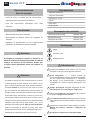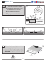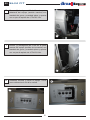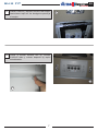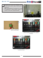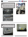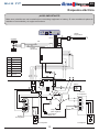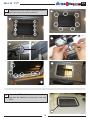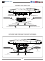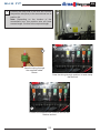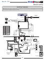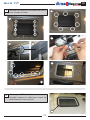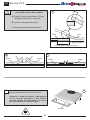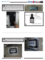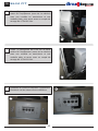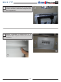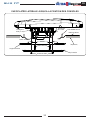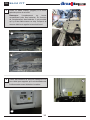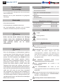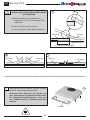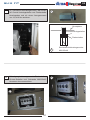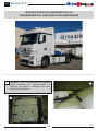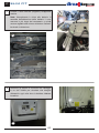
1
Air conditioning for vehicles
SLIM FIT
MERCEDES
EURO 6
F-4218 rev.01
Instrucciones de Montaje
Mounting Instructions
Instructions de Montage
Montageanweisungen
Istruzioni di Montaggio
ES
Spanish
EN
English
FR
French
GE
German
IT
Italian
220AA35384
ES
SLIM FIT
Air conditioning for vehicles
Herramientas
Recomendaciones
Para el montaje
Juego de Llaves Torx
Juego de Llaves Allen
• Antes de iniciar el montaje leer las instrucciones y
Llave fija 13, 14, 22
seguirlas durante el proceso de instalacion.
• Usar
las
herramientas
adecuadas
para
Tijeras
Flexómetro
cada
Destornillador
operación.
Electricidad
Documentación incluída
• Desconectar la llave de contacto.
Instrucciones de montaje
220.AA3.5384
•
Desconectar la batería antes de empezar el
montaje.
Manual del usuario
220.AA3.5378
Diagnosis de averías
220.AA3.5379
•
Asegurar el conexionado de los componentes
eléctricos, verificando su correcto encaje.
Simbología
Frágil
! Atención
Atención corte!
Si durante el montaje el equipo se inclina ó se
abate la cabina con el equipo montado, se deberá
esperar un mínimo de 60 minutos, desde que
el quipo quede horizontal, antes de ponerlo en
marcha.
Riesgo eléctrico
! Advertencias
! El
personal instalador debe poseer una formación
suficiente en Aire Acondicionado de vehículos.
! dirna
Bergstrom, s. l. queda exenta de
responsabilidad si se producen averías que procedan
de una inadecuada manipulación ó instalación
del equipo, ó por modificaciones y sustituciones
efectuadas sin nuestra expresa autorización por
escrito.
! Atención
Al instalar el equipo de aire acondicionado en el techo
se debe proteger la parte superior de la cabina con un
paño ó manta protectora para evitar posibles arañazos.
! Equipo
precargado con gas refrigerante R-134a.
Al instalar Slimfit en el techo hay que tener en cuenta
que, normalmente, las cabinas que vienen provistas de
(No manipular el circuito de gas refrigerante).
escotilla, tienen una estructura suficiente para soportar
! Véase
procedimiento de garantía del producto
incluido en Diagnosis de Averías.
el peso del equipo. Sin embargo, cuando no ocurra así y
sea necesario realizar corte en el techo ó incluso si en el
! Véase
Manual de Usuario del equipo para el correcto
caso de llevar escotilla el material no es lo suficientemente
funcionamiento del mando a distancia y del panel de
control.
resistente (caso de techo de fibra, plástico, etc...) es el
instalador el que debe decidir, bajo su responsabilidad,
! Al
finalizar la instalación se debe entregar al usuario:
Manual del Usuario, Garantía y Diagnosis de
averías.
sobre la necesidad de reforzar el techo para evitar
posibles deformaciones, roturas, entradas de agua, etc...
! El
equipo no cumple con la normativa ADR.
habilitando los medios para que esto no ocurra.
2
SLIM FIT
1
Air conditioning for vehicles
Desmontar escotilla y los elementos de fijación y
entregar éstos al cliente.
1
1
1
1
1
1
1
2
Pegue la junta EPDM 25x15 alrededor del hueco
escotilla (mirar detalle para cortar los bordes
finales de la unión de la junta).
2
3
ES
ES
SLIM FIT
Air conditioning for vehicles
COMO CORTAR LA JUNTA EPDM PARA EVITAR
FILTRACIÓN DE AGUA EN LA CABINA
!
15 mm
A
A- Pegar la junta, manteniendo 100 mm
de papel protector por cada lado.
B- Quita los dos piezas de papel.
C- Pegue presionado ambos finales.
Junta
Junta
Techo cabina
100 mm Aprox. (papel protector)
C
B
Junta
Junta
Junta
Junta
Eliminar
3
3
Posicionar el equipo sobre la junta introduciendo
el frente en el hueco de escotilla.
¡Atención! Al colocar el equipo sobre el
hueco escotilla, verificar que las salidas
de desagüe no queden obstruidas por la
junta EPDM.
Escotilla
4
SLIM FIT
4
ES
Air conditioning for vehicles
Roscar (4) hexagonos M8/125x40 con arandela
goma, arandela plana y apretar con un par de
apriete de 12,7±10 Nm.
4
Base
Arandela goma
Arandela plana
4
5
Colocar soportes de fijación con arandela
plana, arandela grower y tornillo M8/125x45
sin apretar.
5
5
5
Hexágono M8/125x40
ES
6
SLIM FIT
Air conditioning for vehicles
Roscar (2) hexágonos M6 L=19 en la parte
delantera del equipo (sentido marcha) con
arandela de goma y arandela plana y apretar
con un par de apriete de 4,75±10% Nm.
6
7
Roscar (2) hexágonos M6 L=68 en la parte
trasera del equipo (sentido de la marcha) con
arandela de goma y arandela plana y apretar
con un par de apriete de 4,75±10% Nm.
7
8
Presentar consola y mover el equipo. Tomar
como referencia el riel de la cortina.
8
6
8
SLIM FIT
9
Air conditioning for vehicles
Retirar consola y apretar tornillos M8/125x45
hasta hacer tope con los hexágonos para fijar
el equipo.
ES
9
10 Volver a montar consola con (4) tornillos
6/100x15 allen y colocar después (4) tapón
embellecedor.
10
10
7
ES
SLIM FIT
Air conditioning for vehicles
VISTA EXPLOSIONADA MONTAJE
Arandela goma
Arandela goma
Arandela plana Ø 6
Arandela plana Ø 6
(2) M6 M-H L=19
(2) M6 M-H L=68
Junta EPDM 25x15
techo cabina
canalizador
Frente
Separador L=10
Tornillo 8/125x45
Tornillo 8/125x45
Tornillo 6/100x15 allen
Tornillo 6/100x15 allen
VISTA EXPLOSIONADA HASTA LA FIJACIÓN DE LOS SOPORTES
Junta EPDM 25x15
Techo cabina
Arandela goma
Arandela plana Ø 8
M8 M-H L=40
M8 M-H L=40
Soporte fijación
8/125x45
8/125x45
8
Tapizado
SLIM FIT
ES
Air conditioning for vehicles
VISTA EXPLOSIONADA LATERAL HASTA LA FIJACIÓN DE LAS CONSOLAS
hexágono
M-H L 68
Hexágono
M-H (L=19)
Junta EPDM 25x15
Techo cabina
Frente
M8/125x45
Tapizado
Soporte fijación
6/100x15 allen
9
Consola
ES
SLIM FIT
Air conditioning for vehicles
INSTRUCCIONES DETALLADAS SOBRE
CONEXIÓN CABLEADO ALIMENTACIÓN
1
Conectar el cable de alimentación al equipo, fijar
al techo con soportes con adhesivo y bridas.
Después bajar el cableado por la parte trasera
de la cabina.
1
10
1
SLIM FIT
2
Air conditioning for vehicles
Conectar el otro extremo del cableado y llevar
el cable positivo (azul) a caja de conexiones en
posición X4.
Nota: Dependiendo de la ubicación de la caja
de conexiones el cable positivo sobrará en
longitud. Cortar éste a longitud deseada.
2
2
2
Introducir cableado por
gomino suministrado
Pasar cableado por posición X4 y grapar
terminal
2
Colocar fusible suministrado 30A y fijar con
arandela y tuerca
11
ES
ES
3
SLIM FIT
Air conditioning for vehicles
Llevar el cable marrón (negativo) a caja especial
para ello.
Nota: Normalmente suele estar cerca de las
baterías. Dependiendo de la ubicación de las
baterías sobrará cableado marrón, cortar a
medida deseada y grapar terminal suministrado.
3
3
3
4
Colocar adhesivos seguridad cableado, en
un lugar visible para recordar que hay que
desconectarlo cada vez que se quiera abatir la
cabina.
4
12
4
SLIM FIT
ES
Air conditioning for vehicles
Esquema eléctrico
¡AVISO IMPORTANTE!
Make sure polarities are not inverted when connecting equipment to battery. Si esto sucediera la placa de
mandos no se enciende y el equipo no funciona.
ºC
ºF
TEMP
Sonda
temperatura
ON/OFF
Cinta
Soplador
Na
Control
electrónico
Az
Azul
N
Negro
R
Rojo
V
Verde
B
Blanco
A
Amarillo
Na
Naranja
M
Marrón
Fusible 10A
+
-
Electro
Control
1º Compresor
-
-
+
+
F
D
C
P
T
Control
2º Compresor
Fusible 30 A
Caja especial
para negativos
+
+
+
F
D
C
P
T
Caja positivos
posición X4
2 Compresor
1 Compresor
13
EN
SLIM FIT
Air conditioning for vehicles
Tools
Assembly
Recommendations
Torx wrenches set
Allen wrenches set
• Before starting assembly, please read instructions
and follow them during installation process.
Open-jawed spanner 13, 25
Scissors
• Use the adequate tools for each operation.
Flexo-meter
Screwdriver
Electricity
• Disconnect ignition key.
Documentation included
• Disconnect battery before starting assembly.
• Make sure electric components are securely
connected, checking their correct fitting.
Mounting instructions
220.AA3.5384
User’s guide
220.AA3.5378
Troubleshooting
220.AA3.5379
Symbology
Fragile
! Warning
Beware of cuts!
If the unit slants during assembly, wait for at
least 60 minutes with the unit in horizontal
position before starting it up.
Electrical hazard
! Warnings
! The
installing personnel must have a sufficient
training in vehicles air conditioning.
! dirna
Bergstrom, s. l. shall not be responsible for
! Warning
breakdowns or damages coming from an inadequate
handling or installation of the equipment or from
When installing air conditioning equipment on roof, the
modifications and substitutions carried out without
upper cabin part must be protected with a cloth or a
our express and written authorisation.
protective blanket to avoid possible scratches. When
! Equipment
pre-charged with refrigerating gas.
installing Slimfit on roof, take into account that, normally,
(Do not handle refrigerating gas circuit).
cabins equipped with a hatch have a strong enough
! Please
see product warranty procedure included in
structure to hold equipment weight. However, if it is not
Troubleshooting diagnosis.
the case and it is necessary to carry out a cut in the roof
! Please
see equipment User’s Guide for its correct
or, although it has a hatch, the material is not resistant
functioning of the remote control and control panel.
enough (if roof is made of fibre, plastic, etc...), it is the
installer who will have to decide, under his responsibility,
! Once
installation is finished, the following documents
if it is necessary to reinforce the roof to avoid possible
must be handed over to the user: User’s Guide,
deformations, breaks, water entries, etc., habilitating the
Warranty and Troubleshooting Diagnosis.
! The
unit does not comply with ADR regulations.
means required to stop it from occurring.
14
SLIM FIT
1
Air conditioning for vehicles
Take down the hatch and the fastening elements,
and hand them over to the customer.
1
1
1
1
1
1
1
2
Attach the EPDM 25x15 seal around the hatch
gap (see the details to cut the ends of the seal
joint).
2
15
EN
EN
SLIM FIT
Air conditioning for vehicles
HOW TO CUT EPDM GASKET TO AVOID
WATER FILTRATION INTO THE CABIN
!
15 mm
A
A- Glue gasket, keeping 100 mm of protection
paper at each side.
B- Remove the two pieces of paper.
C- Glue by pressing both ends.
Gasket
Gasket
Cabin roof
100 mm Approx. (protection paper)
C
B
Gasket
Gasket
Gasket
Gasket
Remove
3
3
Position the unit on the seal, introducing the front
in the hatch gap.
Caution! When positioning the unit above
the hatch gap, check that the wastewater
run-offs are not blocked by the EPDM
seal.
Hatch
16
SLIM FIT
4
EN
Air conditioning for vehicles
Screw (4) M8/125x40 hexagons with rubber
washer and flat washer, and tighten with a torque
of 12.7±10 Nm.
4
Base
Rubber washer
Flat washer
4
5
Position the fastening mounts with a flat
washer, grower washer and M8/125x45 screw,
without tightening.
5
17
5
Hexagon M8/125x40
EN
6
SLIM FIT
Air conditioning for vehicles
Screw (2) M6 L=19 hexagons on the front of
the unit (direction of travel) with rubber washer
and flat washer, and tighten with a torque of
4.75±10% Nm.
6
7
Screw (2) M6 L=68 hexagons on the rear of
the unit (direction of travel) with rubber washer
and flat washer, and tighten with a torque of
4.75±10% Nm.
7
8
Position the console and move the unit. Use the
curtain rail as a reference.
8
18
8
SLIM FIT
9
Air conditioning for vehicles
Remove the console and tighten M8/125x45
screws until it comes up against the hexagons
in order to secure the unit.
EN
9
10 Replace the console with (4) 6/100x15 Allen
screws and then position (4) decorative
caps.
10
10
19
EN
SLIM FIT
Air conditioning for vehicles
ASSEMBLY EXPLODED VIEW
Rubber washer
Rubber washer
Ø6 Flat washer
Ø6 Flat washer
(2) M6 M-H L=19
(2) M6 M-H L=68
25x15 EPDM seal
Cabin roof
duct unit
Front
L=10 Spacer
8/125x45 Screw
8/125x45 Screw
6/100x15 Allen screw
6/100x15 Allen screw
EXPLODED VIEW THROUGH TO MOUNT FASTENINGS
25x15 EPDM seal
Cabin roof
Rubber washer
Ø8 Flat washer
M8 M-H L=40
M8 M-H L=40
Fastening mount
8/125x45
8/125x45
20
Upholstery
SLIM FIT
EN
Air conditioning for vehicles
EXPLODED SIDE VIEW THROUGH TO CONSOLE ATTACHMENT
M-H Hexagon
25x15 EPDM seal
L 68
M-F Hexagon
(L=19)
Cabin roof
Front
M8/125x45
Upholstery
Fastening mount
6/100x15 allen
21
Console
EN
SLIM FIT
Air conditioning for vehicles
DETAILED INSTRUCTIONS ON
POWER CABLE CONNECTION
1
Connect the power cable to the unit, secure
to the roof with the mounts and adhesive and
flanges. Then lower the wiring through the rear
of the cabin.
1
22
1
SLIM FIT
2
Air conditioning for vehicles
Connect the other end of the wire and connect
the positive wire (blue) to the connections box in
position X4.
Note: Depending on the location of the
connections box, the positive wire will have
excess length. Cut this to the required length.
EN
2
2
2
Pass the wiring through
the supplied rubber
sleeve
Pass the wiring through position X4 and clamp
the terminal
2
Position the supplied 30A fuse and secure with
washer and nut
23
EN
3
SLIM FIT
Air conditioning for vehicles
Run the brown wire (negative) to the specially
fitted box.
Note: This is normally close to the batteries.
Depending on the location of the batteries, the
brown wire will have excess length; cut to the
required size and clamp the supplied terminal.
3
3
3
4
Position wire safety stickers in a visible place as
a reminder to disconnect every time the cabin is
tilted.
4
24
4
SLIM FIT
EN
Air conditioning for vehicles
Electric wiring
IMPORTANT WARNING!
Take care not to invert the polarities when connecting the unit to the battery. If this happens, the control plate
does not come on and the unit does not work.
ºC
ºF
TEMP
Temperature
probe
ON/OFF
Wiring strip
Blower
Na
Electronic
module
Az
Blue
N
Black
R
Red
V
Green
B
White
A
Yellow
Na
Orange
M
Brown
10 A. Fuse
+
-
Fan
Compressor
electronic
module
-
-
+
+
F
D
C
P
T
30 A. Fuse
Special box for
negatives
+
+
+
F
D
C
P
T
Positives box
position X4
Compressor
electronic
module
Compressor
Compressor
25
FR
SLIM FIT
Air conditioning for vehicles
Outils
Recommendations
Pour Le Montage
Jeu de clés Torx
Jeu de clés Allen
• Avant de commencer le montage de l’appareil, prière de
Clé fixe 13, 14, 22
lire les instructions et de les suivre attentivement.
Ciseaux
Mètre
• Utiliser les outils convenant à chaque opération.
Tournevis
Electricity
• Déconnecter la clé de contact.
Documentation included
•
Déconnecter la batterie avant de commencer le
montage.
• Vérifier le câblage des composants électriques et leur
correcte installation.
Instructions de montage
220.AA3.5384
Guide de l’utilisateur
220.AA3.5378
Solution des problèmes
220.AA3.5379
Symbologie
! Attention
Fragile
Si pendant le montage l’équipement est incliné,
il faudra attendre au moins 60 minutes avant de
le mettre en marche une fois qu’il aura été remis
sur sa position horizontale.
Attention aux coupures !
Risque électrique
! Garantie
! L’installateur
devra posséder la formation pertinente
en air conditionné sur véhicules.
! Attention
! dirna
Bergstrom, s.l., ne sera pas responsable
des dommages ou des bris dérivés d’une
installation ou d’une manipulation incorrecte ni
des modifications réalisées sans autorisation
expresse par écrit.
Lors de l’installation de l’appareil d’air conditionné sur le
toit, il faudra protéger la partie supérieure de la cabine
avec un linge ou une couverture de protection afin
d’éviter les éventuelles égratignures.
! Appareil
pré-chargé de gaz réfrigérant R-134. (Ne
Durant l’installation du Slimfit, tenir compte du fait que
pas manipuler le circuit de gaz réfrigérant).
normalement les cabines pourvues d’écoutille possède
! Voir
la procédure de garantie du produit au
une structure suffisamment solide pour supporter le
Diagnostic de problèmes.
poids de l´appareil. Cependant, si ce n’est pas le cas
! Voir
le Guide de l’Usager de l’appareil pour le
et qu’il est nécessaire de découper le toit ou même si
disposant d’écoutille, la structure n’est pas suffisamment
fonctionnement correcte de la télécommande et du
tableau de commande.
rigide (si elle était en fibre, plastique, etc.) il appartiendra
! Après
l’installation, vous devez fournir à l’utilisateur:
Manuel d’utilisation, garantie et diagnostic de
pannes.
à l’installateur de décider s’il faut renforcer le toit pour
éviter toute déformation, rupture ou voie d’eau, etc., et
! L’équipement
ne remplit pas la norme ADR.
prendre les mesures nécessaires à cet effet.
26
SLIM FIT
1
Air conditioning for vehicles
Démonter l’écoutille et les éléments de fixation
et les remettre au client.
1
1
1
1
1
1
1
2
Coller le joint EPDM 25x15 autour du creux de
l’écoutille (observer le détail pour couper les
bords finaux de l’union du joint).
2
27
FR
FR
SLIM FIT
Air conditioning for vehicles
COMO CORTAR LA JUNTA EPDM PARA EVITAR
FILTRACIÓN DE AGUA EN LA CABINA
!
15 mm
A
A- Pegar la junta, manteniendo 100 mm
de papel protector por cada lado.
B- Quita los dos piezas de papel.
C- Pegue presionado ambos finales.
Junta
Junta
Techo cabina
100 mm Aprox. (papel protector)
C
B
Junta
Junta
Junta
Junta
Eliminar
3
3
Placer l’équipement sur le joint en introduisant la
partie frontale dans le creux de l’écoutille.
Attention ! Avant de placer l’équipement
sur le creux de l’écoutille, il faut vérifier
que les sorties d’écoulement ne soient
pas bouchées par le joint EPDM.
Écoutille
28
SLIM FIT
4
FR
Air conditioning for vehicles
Visser (4) hexagones M8/125x40 avec une
rondelle en caoutchouc, une rondelle plate et
serrer avec un couple de serrage de 12,7±10
Nm.
4
Base
Rondelle
caoutchouc
Rondelle plate
4
5
Placer les supports de fixation avec une rondelle
plate, rondelle grower et vis M8/125x45 sans
serrer.
5
29
5
Hexagone M8/125x40
FR
6
SLIM FIT
Air conditioning for vehicles
Visser (2) hexagones M6 L=19 sur la partie
avant de l’équipement (sens de la marche)
avec une rondelle en caoutchouc et une
rondelle plate, puis serrer avec un couple de
serrage de 4,75±10% Nm.
6
7
Visser (2) hexagones M6 L=68 sur la partie
arrière de l’équipement (sens de la marche)
avec une rondelle en caoutchouc et une
rondelle plate et serrer avec un couple de
serrage de 4,75±10% Nm.
7
8
Présenter la console et déplacer l’équipement.
Prendre le rail du rideau comme référence.
8
30
8
SLIM FIT
9
Air conditioning for vehicles
Retirer la console et serrer les vis M8/125x45
jusqu’à atteindre la butée des hexagones pour
fixer l’équipement.
FR
9
10 Monter à nouveau la console avec (4) vis
6/100x15 allen et placer ensuite (4) bouchon
enjoliveur.
10
10
31
FR
SLIM FIT
Air conditioning for vehicles
VUE ÉCLATÉE MONTAGE
Rondelle caoutchouc
Rondelle caoutchouc
Rondelle plate Ø 6
Rondelle plate Ø 6
(2) M6 M-H L=19
(2) M6 M-H L=68
Joint EPDM 25x15
Plafond cabine
Canalisateur
Partie frontale
Séparateur L=10
Vis 8/125x45
Vis 8/125x45
Vis 6/100x15 allen
Vis 6/100x15 allen
VUE ÉCLATÉE JUSQU’À LA FIXATION DES SUPPORTS
Joint EPDM 25x15
Rondelle
caoutchouc
Rondelle plate Ø 8
M8 M-H L=40
M8 M-H L=40
Support fixation
8/125x45
8/125x45
32
Plafond cabine
Tapisserie
SLIM FIT
FR
Air conditioning for vehicles
VUE ÉCLATÉE LATERALE JUSQU’A LA FIXATION DES CONSOLES
Hexagone
M-H L 68
Hexagone
M-H (L=19)
Joint EPDM 25x15
Plafond cabine
Partie frontale
M8/125x45
Tapisserie
Support fixation
6/100x15 allen
33
Console
FR
SLIM FIT
Air conditioning for vehicles
INSTRUCTIONS DÉTAILLÉES SUR LA CONNEXION DU
CÂBLAGE D’ALIMENTATION
1
Connecter
le
câble
d’alimentation
à
l’équipement, fixer au plafond avec des supports
à l’aide d’adhésifs et de brides. Ensuite, baisser
l’équipement par la partie arrière de la cabine.
1
34
1
SLIM FIT
2
Air conditioning for vehicles
Connecter l’autre extrémité du câblage et porter
le câble positif (bleu) à la boîte de jonction sur la
position X4.
Remarque: en fonction de l’emplacement de la
boîte de jonction, il est possible qu’il y ait de la
longueur en trop. Couper à la longueur désirée.
FR
2
2
2
Introduire le câblage par
l’élément cannelé fourni
Passer le câblage par la position X4 et agrafer
le terminal
2
Placer le fusible fourni 30A et fixer avec
rondelle et écrou
35
FR
3
SLIM FIT
Air conditioning for vehicles
Porter le câble marron (négatif) à la boîte
spéciale prévue à cet effet.
Remarque:
l’emplacement
se
trouve
normalement près des batteries. En fonction
de l’emplacement des batteries, il est possible
qu’il y ait du câble marron en trop. Couper à la
mesure désirée et agrafer le terminal fourni.
3
3
3
4
Placer des adhésifs de sécurité câblage sur un
lieu visible pour rappeler qu’il est nécessaire de
le déconnecter avant d’abattre la cabine.
4
36
4
SLIM FIT
FR
Air conditioning for vehicles
Schéma électrique
AVIS IMPORTANT !
Attention ! Ne pas inverser les polarités au moment de connecter l’équipement à la batterie. Si cela se
produisait, la plaque de commandes ne s’allumerait pas et l’équipement ne fonctionnerait pas.
ºC
TEMP
ºF
Sonde
température
ON/OFF
Bande
Souffleur
Na
Contrôle
électronique
Az
Bleu
N
Noir
R
Rouge
V
Vert
B
Blanc
A
Jaune
Na
Orange
M
Marron
Fusible 10A
+
-
Electro
Contrôle 1er
Compresseur
-
-
+
+
F
D
C
P
T
Contrôle 2º
Compresseur
Fusible 30 A
Boîtier spécial
pour négatifs
+
+
+
F
D
C
P
T
Boîtier positifs
position X4
2 Compresseur
37
1 Compresseur
GE
SLIM FIT
Air conditioning for vehicles
Werkzeuge
Empfehlungen
Zur montage
Torx-Schraubenschlüssel
Inbusschraubenschlüssel
• Vor und während der Montage bitte diese Anweisungen
10er, 13er, 14er Schraubenschlüssel
lesen und beachten.
Schere
•B
enutzen Sie für jeden Arbeitsschritt die geeigneten
Metermaß
Werkzeuge.
Schraubendreher
Elektrizität
Mitgelieferte unterlagen
• Zündschlüssel abziehen.
Montageanweisungen
220.AA3.5384
•V
or Montagebeginn die Batterie abklemmen.
Benutzerleitfaden
220.AA3.5378
Fehlerdiagnose
220.AA3.5379
• Den ordnungsgemäßen Anschluss und die korrekte
Installation der Elektrokomponenten überprüfen.
Symbolik
Fragile
! Achtung
Achtung Gericht!
Sollte sich das Gerät während der Montage
neigen, muss man mindestens 60 Minuten
warten, nachdem es wieder in die horizontale
Lage gebracht wurde, um es wieder
einzuschalten.
Elektrische Gefährdung
! Warnhinweise
! Der
Installateur muss im Bereich Fahrzeug-Klimaanlagen
ausreichend geschult sein.
! Achtung
! dirna
Bergstrom, s.l. übernimmt keine Verantwortung
für
Wird die Klimaanlage im Kabinendach installiert,
muss der obere Teil der Kabine mit einem Tuch oder
einer Decke gegen eventuelle Kratzer geschützt
werden. Bei der Installation der Slimfit auf dem
Kabinendach muss darauf geachtet werden,
dass mit Luken ausgestattete Kabinen über eine
ausreichend stabile Struktur verfügen, um das
Gewicht des Geräts Stand zu halten. Sollte das
Fahrzeug über keine Luke verfügen und sollte es
notwendig sein, das Kabinendach aufzuschneiden,
bzw. sollte die vorhandene Struktur nicht ausreichend
stabil sein (z.B. wenn sie aus Faser, Kunststoff
usw. hergestellt ist), obliegt es dem Installateur zu
entscheiden, ob das Kabinendach zur Vermeidung
von Verformungen, Brüchen, undichten Stellen usw.
verstärkt werden muss, und die hierfür notwendigen
Mittel bereit zu stellen.
Schäden
oder
Brüche
aufgrund
einer
nicht
ordnungsgemäßen Installation oder Bedienung des
Geräts oder den Austausch von Teilen bzw. Umbauten,
die ohne die erforderliche schriftliche Genehmigung
durchgeführt wurden.
! Mit
Kältemittel
vorgefülltes
Gerät
R-134a.
(Kältemittelkreislauf nicht manipulieren).
! Siehe
Garantieverfahren des Produkts in der
Fehlerdiagnose.
! Siehe
Benutzerleitfaden
des
Geräts
für
den
ordnungsgemäßen Betrieb der Fernbedienung und des
Bedienfelds.
! Die
folgenden Unterlagen müssen dem Benutzer nach der
Installation ausgehändigt werden: Benutzerleitfaden,
Garantie und Fehlerdiagnose.
! Die Anlage erfüllt nicht die ADR-Vorschriften.
38
SLIM FIT
1
Air conditioning for vehicles
Luke
und
deren
Befestigungselemente
ausbauen und diese dem Kunden aushändigen.
1
1
1
1
1
1
1
2
EPDM-Dichtung
(25x15
mm)
um
die
Lukenaussparung
herum
kleben
(siehe
Detailzeichnung für das Zurechtschneiden der
äußeren Fugenränder der Dichtung).
2
39
GE
GE
!
SLIM FIT
Air conditioning for vehicles
WIE DIE EPDM-DICHTUNG GESCHNITTEN
A WIRD, UM FILTRATIONEN IN DER KABINE
ZU VERMEIDEN
15 mm
A
A- Dichtung aufkleben und dabei einen
Papierschutz von 100 mm auf jeder Seite
beibehalten.
B- Die zwei Papierstücke entfernen.
C- Unter Anpressen beider Enden aufkleben.
Dichtung
Dichtung
Kabinendach
Ca. 100 mm (Schutzpapier)
C
B
Dichtung
Dichtung
Dichtung
Dichtung
Entfernen
3
3
Gerät auf die Dichtung stellen und die Frontseite
durch die Lukenaussparung stecken.
Achtung! Beim Auflegen des Geräts auf
die Lukenaussparung darauf achten, dass
die Entwässerungsausgänge nicht von
der EPDM-Dichtung zusammengedrückt
werden.
Escotilla
40
SLIM FIT
4
GE
Air conditioning for vehicles
(4) Sechskant-Verbindungsmuttern M8/125x40
mit Gummi-Unterlegscheibe und Flachscheibe
einschrauben und mit einem Anzugsmoment
von 12,7±10 Nm anziehen.
4
Grundplatte
Gummiunterlegscheibe
Flachscheibe
4
5
Befestigungshalterungen mit Flachscheibe,
Grower-Scheibe und Schraube M8/125x45
einsetzen ohne anzuziehen.
5
41
5
Sechskant-Verbindungsmutter
M8/125x40
GE
6
SLIM FIT
Air conditioning for vehicles
(2) Sechskant-Verbindungsmuttern M6 L=19
am vorderen Teil des Geräts (Fahrtrichtung)
mit Gummi-Unterlegscheibe und Flachscheibe
einschrauben und mit einem Anzugsmoment
von 4,75±10% Nm anziehen.
6
7
(2) Sechskant-Verbindungsmuttern M6 L=68
am hinteren Teil des Geräts (Fahrtrichtung)
mit Gummi-Unterlegscheibe und Flachscheibe
einschrauben und mit einem Anzugsmoment
von 4,75±10% Nm anziehen.
7
8
Konsole auflegen und das Gerät bewegen. Als
Referenz die Gardinenschiene nehmen.
8
42
8
SLIM FIT
9
Air conditioning for vehicles
Konsole entfernen und Schrauben M8/125x45
bis zum Anschlag an die SechskantVerbindungsmuttern anziehen, um das Gerät
zu befestigen.
GE
9
10 Konsole mit (4) Innensechskantschrauben
6/100x15 wieder montieren und danach (4)
Zierkappen aufsetzen.
10
10
43
GE
SLIM FIT
Air conditioning for vehicles
EXPLOSIONSANSICHT MONTAGE
Gummiunterlegscheibe
Gummiunterlegscheibe
Flachscheibe Ø 6
Flachscheibe Ø 6
(2) M6 M-H L=68
(2) M6 M-H L=19
EPDM-Dichtung 25x15
Kabinendecke
Kabelführung
Frontteil
Distanzstück L=10
Schraube 8/125x45
Schraube 8/125x45
Schraube 6/100x15
Innensechskant
Schraube 6/100x15
Innensechskant
EXPLOSIONSANSICHT BIS ZUR BEFESTIGUNG DER HALTERUNGEN
EPDM-Dichtung 25x15
Kabinendecke
Gummiunterlegscheibe
Flachscheibe Ø 8
M8 M-H L=40
M8 M-H L=40
Befestigungshalterung
8/125x45
8/125x45
44
Verkleidung
SLIM FIT
GE
Air conditioning for vehicles
SEITLICHE EXPLOSIONSANSICHT BIS ZUR BEFESTIGUNG DER KONSOLEN
Sechskant-Verbindungsmutter
M-H L 68
EPDM-Dichtung 25x15
Sechskant-Verbindungsmutter
M-H (L=19)
Kabinendecke
Frontteil
M8/125x45
Verkleidung
Befestigungshalterung
6/100x15 allen
45
Konsole
GE
SLIM FIT
Air conditioning for vehicles
DETAILLIERTE HINWEISE ZUM
ANSCHLUSS DES NETZKABELS
1
Netzkabel an das Gerät anschließen, an der
Decke mit Klebehaltern und Kabelhaltern
befestigen. Danach die Kabel über die Rückseite
der Kabine nach unten führen.
1
46
1
SLIM FIT
2
Air conditioning for vehicles
Das andere Ende des Kabels anschließen und
das positive Kabel (blau) zum Anschlusskasten
Position X4 führen.
Hinweis: Je nach dem Standort des
Anschlusskastens ist das positive Kabel zu lang.
Auf die gewünschte Länge kürzen.
2
2
2
Kabel durch das mitgelieferte
Gummiteil führen.
Kabel durch die Position X4 führen und
Kabelschuh befestigen.
2
Mitgelieferte 30A Sicherung anbringen und mit
Unterlegscheibe und Mutter befestigen.
47
GE
GE
3
SLIM FIT
Air conditioning for vehicles
Braunes
Kabel
(negativ)
zum
hierfür
vorgesehenen Kasten führen.
Hinweis: Dieser befindet sich normalerweise in
der Nähe der Batterien. Je nach dem Standort
der Batterien ist das braune Kabel zu lang.
Auf die gewünschte Länge kürzen und den
mitgelieferten Kabelschuh anbringen.
3
3
3
4
Sicherheitsaufkleber der Kabel an sichtbarer
Stelle anbringen, damit daran gedacht wird,
dieses bei jedem Abklappen der Kabine
abzuziehen.
4
48
4
SLIM FIT
GE
Air conditioning for vehicles
Schaltplan
WICHTIGER HINWEIS!
Achtung! Die Polaritäten beim Anschluss der Anlage an die Batterie nicht vertauschen. Ist dies der Fall,
schaltet sich die Bedientafel nicht ein und das Gerät funktioniert nicht.
ºC
ºF
TEMP
ON/OFF
Temperaturfühler
Flachkabel
Gebläse
Na
Elektroniksteuerung
Az
Blau
N
Chwarz
R
Rot
V
Grün
B
Weiss
A
Gelb
Na
Oranbe
M
Braun
Sicherung 10A
+
-
Elektrolüfter
Steuerung
1. Verdichter
-
-
+
+
F
D
C
P
T
Steuerung
2. Verdichter
Sicherung 30 A
Spezialkasten für
Negativkabel
+
+
+
F
D
C
P
T
Kasten Positivkabel
Position X4
2 Verdichter
1 Verdichter
49
IT
SLIM FIT
Air conditioning for vehicles
Attrezzi
Suggerimenti
per il montaggio
Kit di chiavi Torx
Kit di chiavi Allen
• Prima di cominciare il montaggio, leggere attentamente
Chiave fissa 10, 13, 14
le istruzioni e rispettarle nel corso dello stesso.
Forbici
Metro a nastro
• Usare gli attrezzi più adatti ad ogni operazione.
Cacciavite
Elettricitá
Documentazione allegata
• Scollegare la chiave di contatto.
•S
collegare la batteria prima di cominciare il montaggio.
•A
ssicurarsi
di
aver
effettuato
correttamente
l’installazione e il collegamento dei componenti elettrici.
Istruzioni di montaggio
220.AA3.5384
Guida dell’utente
220.AA3.5378
Soluzione dei problemi
220.AA3.5379
Simbologia
Fragile
! Attenzione
Attenzione alle mani
Se durante il montaggio si inclina l’impianto,
prima di rimetterlo in funzione occorre attendere
almeno 60 minuti dal momento in cui è di nuovo
in posizione orizzontale.
Tensione elettrica pericolosa
! Avvertenze
! L’installatore
deve essere in possesso della
formazione necessaria in materia di aria condizionata
per veicoli.
! dirna
Bergstrom, s.l. declina ogni responsabilità
! Attenzione
per danni o rotture derivanti dall’errata installazione
o dall’errato uso dell’impianto o da sostituzioni
o modifiche effettuate senza la necessaria
autorizzazione per iscritto.
Quando si installa l’impianto di aria condizionata sul
tettuccio, bisogna proteggere la parte superiore della
! Impianto
precaricato con gas refrigerante R-134.
cabina con uno straccio o una coperta per evitare eventuali
graffi.
(Non manomettere il circuito di gas refrigerante).
Per l’installazione del Slimfit, tenere presente
! Vedi
la procedura di garanzia del prodotto in
che normalmente le cabine munite di oblò dispongono
Diagnosi dei problemi.
di una struttura abbastanza solida per sostenere il peso
dell’impianto. Tuttavia, se così non fosse e se fosse
! Vedi
la Guida dell’utente dell’impianto per il corretto
funzionamento del telecomando e del pannello di
controllo.
necessario tagliare il tettuccio, o se in presenza di oblò la
struttura non fosse abbastanza rigida (se fosse di fibra,
! I seguenti documenti devono essere consegnati
plastica, ecc.), è responsabilità dell’installatore decidere
all’utente una volta conclusa l’installazione: Guida
dell’utente, Garanzia e Diagnosi dei problemi.
se occorre rinforzare il tettuccio per evitare qualsiasi
deformazione, rottura o penetrazione d’acqua, ecc.,
! L’impianto
non è conforme alla normativa ADR.
prendendo le misure necessarie per evitarlo.
50
SLIM FIT
1
Air conditioning for vehicles
Smontare il coperchio del tettuccio apribile e gli
elementi di fissaggio e consegnarli al cliente.
1
1
1
1
1
1
1
2
Incollare la guarnizione EPDM 25x15 intorno al
vano del tettuccio apribile (vedi il particolare per
tagliare i bordi finali di attacco della guarnizione).
2
51
IT
IT
!
SLIM FIT
Air conditioning for vehicles
INCOLLARE LA GUARNIZIONE EPDM INTORNO
A AL FORO DELL’OBLÒ (VEDI PARTICOLARE
PER TAGLIARE I BORDI)
15 mm
A
A- Incollare la guarnizione mantenendo una
protezione di carta di 100 mm su ogni lato.
B- Rimuovere i due pezzi di carta.
C- Incollare
estremità.
premendo
su
entrambe
le
Guarnizione
Guarnizione
Tettuccio della
cabina
Circa 100 mm (carta protettiva)
C
B
Guarnizione
Guarnizione
Guarnizione
Guarnizione
Rimuovere
3
3
Sistemare l’impianto sulla guarnizione inserendo
il frontalino nel vano del tettuccio.
Attenzione! Quando si sistema l’impianto
sul vano del tettuccio apribile, verificare
che le uscite di scarico non siano ostruite
dalla guarnizione EPDM.
Tettuccio
apribile
52
SLIM FIT
4
IT
Air conditioning for vehicles
Avvitare (4)perni esagonali M8/125x40 con
rondella di gomma e rondella piana e stringere
con una coppia di serraggio di 12,7±10 Nm.
4
Base
Rondella di
gomma
Rondella piana
4
5
Inserire i supporti di fissaggio con rondella
piana, rondella grower e vite M8/125x45,
senza stringere.
5
53
5
Perno esagonale
M8/125x40
IT
SLIM FIT
6
Avvitare (2) perni esagonali M6 L=19 nella
parte anteriore dell’impianto (senso di marcia)
con rondella di gomma e rondella piana e
stringere con una coppia di serraggio di
4,75±10% Nm.
Air conditioning for vehicles
6
7
Avvitare (2) perni esagonali M6 L=68 nella parte
posteriore dell’impianto (senso di marcia) con
rondella di gomma e rondella piana e stringere
con una coppia di serraggio di 4,75±10% Nm.
7
8
Montare provvisoriamente la console e spostare
l’impianto. Prendere come riferimento la barra
della tendina.
8
54
8
SLIM FIT
9
Air conditioning for vehicles
Rimuovere la console e stringere le viti
M8/125x45 fino a battuta con i perni esagonali
per fissare l’impianto.
IT
9
10 Rimontare la console con (4) viti 6/100x15 a
brugola e quindi inserire (4) tappini decorativi.
10
10
55
IT
SLIM FIT
Air conditioning for vehicles
ESPLOSO MONTAGGIO
Rondella di gomma
Rondella di gomma
Rondella piana Ø 6
Rondella piana Ø 6
(2) M6 M-H L=19
(2) M6 M-H L=68
Guarnizione EPDM 25x15
Tettuccio cabina
Canalizzatore
Frontalino
Separatore L=10
Vite 8/125x45
Vite 8/125x45
Vite a brugola 6/100x15
Vite a brugola 6/100x15
ESPLOSO FINO AL FISSAGGIO DEI SUPPORTI
Guarnizione EPDM 25x15
Rondella di
gomma
Rondella piana Ø 8
M8 M-H L=40
M8 M-H L=40
Supporto fissaggio
8/125x45
8/125x45
56
Tettuccio cabina
Tappezzeria
SLIM FIT
IT
Air conditioning for vehicles
ESPLOSO LATERALE FINO AL FISSAGGIO DELLE CONSOLE
Perno esagonale
M-H L 68
Guarnizione EPDM 25x15
Perno esagonale
M-F (L=19)
Tettuccio cabina
Frontalino
M8/125x45
Tappezzeria
Supporto fissaggio
6/100x15 allen
57
Console
IT
SLIM FIT
Air conditioning for vehicles
ISTRUZIONI PARTICOLAREGGIATE SULLA
CONNESSIONE DEL CABLAGGIO DI ALIMENTAZIONE
1
Collegare il cavo di alimentazione al gruppo,
fissare al tettuccio con i supporti adesivi e le
fascette. Far passare il cablaggio dalla parte
posteriore della cabina.
1
58
1
SLIM FIT
2
Air conditioning for vehicles
Collegare l’altra estremità del cablaggio e
portare il cavo positivo (blu) alla scatola delle
connessioni in posizione X4.
Nota: a seconda dell’ubicazione della scatola
delle connessioni, il cavo positivo è più lungo
del necessario. Occorre perciò tagliarlo alla
lunghezza richiesta.
2
2
2
Inserire il cablaggio nella
guaina in dotazione
Far passare il cablaggio dalla posizione X4 e
fissare il terminale
2
Montare il fusibile da 30 A in dotazione e
fissare con la rondella e il dado
59
IT
IT
SLIM FIT
3
Portare il cavo marrone (negativo) all’apposita
scatola.
Nota: Normalmente è vicino alle batterie. A
seconda dell’ubicazione delle batterie il cavo
marrone è più lungo del necessario e quindi
occorre tagliarlo alla misura richiesta e fissare il
terminale in dotazione.
Air conditioning for vehicles
3
3
3
4
Attaccare gli adesivi di sicurezza del cablaggio
in un sito visibile per ricordare che bisogna
disinserirlo ogni volta che si desidera ribaltare
la cabina.
4
60
4
SLIM FIT
IT
Air conditioning for vehicles
Schema elettrico
AVVERTENZA IMPORTANTE!
Fare attenzione a non invertire le polarità quando si esegue il collegamento dell’impianto alla batteria. Infatti,
in tal caso il quadro comandi non si accende e l’impianto non funziona.
ºC
TEMP
ºF
Sonda
temperatura
ON/OFF
Nastro
Ventola
Na
Controllo
elettronico
Az
Blu
N
Nero
R
Rosso
V
Verde
B
Bianco
A
Giallo
Na
Arancione
M
Marrone
Fusibile 10A
+
-
Elettroventilatore
Controllo
1º compressore
-
-
+
+
F
D
C
P
T
Controllo
2º compressore
Fusibile 30 A
Scatola speciale
per negativi
+
+
+
F
D
C
P
T
Scatola positivi
posizione X4
2 Compressore
61
1 Compressore
ES
SLIM FIT
Air conditioning for vehicles
62
SLIM FIT
Air conditioning for vehicles
63
ES
Ed:
29/05/2014
Md:
05/03/2015
c
Air conditioning for vehicles
Francisco Alonso, 6
28806 Alcalá de Henares, Madrid
SPAIN
CENTRO DE COMUNICACIONES
COMUNICATION CENTRE
NACIONAL
Centralita /Asistencia Técnica ............................ 918775841
Comercial .............................................................. 918775840
Fax ......................................................................... 918836321
Email.......................................................comercial@dirna.com
INTERNATIONAL
Tec. Assistance ............................................ 0034 918775848
Fax ................................................................ 0034 918836514
Email:........................................................... [email protected]
Export Dept. ................................................. 0034 918775846
Fax..................................................................0034 918771158
www.dirna.com
www.bycool.com
!
ATENCIÓN:
Dirna Bergstrom se reserva el derecho de efectuar modificaciones en cualquier momento de los datos
contenidos en esta publicación, por razones técnicas o comerciales.
!
NOTE:
For technical and commercial reasons, Dirna Bergstrom reserves the right to change the data contained
in this brochure.
!
ATTENTION:
Dirna Bergstrom se réserve le droit d´effectuer à tout moment des modifications des données reprises
sur cette publication, pour des raisons techniques ou commerciales.
!
HIWEIS:
Dirna Bergstrom behält sich vor, aus technischen oder kaufmännischen Gründen jederzeit Änderungen
der Angaben dieser Veröffentlichung vorzunehmen.
!
ATTENZIONE:
Dirna Bergstrom si riserva il diritto di effettuare modifiche in qualsiasi momento ai dati contenuti in questa
pubblicazione, per motivi tecnici o commerciali.