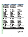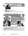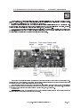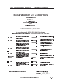
1
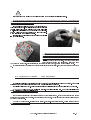
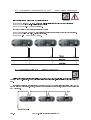
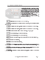
COEF srl. Via Albinatico, 80-82 51019 Ponte Buggianese (PT) MP250 Optic ITALY • MANUALE ISTRUZIONI • OPERATING INSTRUCTION Printed in January 1999 ® COEF srl. Via Albinatico, 80-82 Ponte Buggianese 51019 ( Pistoia ) ITALY tel. (+39) 0572-636536 r.a. Fax (+39) 0572 - 636535 www.coef.it e-mail: [email protected] Tutti i diritti di riproduzione, diffusione del presente manuale sono riservati a COEF srl. Le descrizioni ed illustrazioni fornite nella presente pubblicazione non sono impegnative. COEF srl. si riserva il diritto di apportare in qualsiasi momento tutte le modifiche che riterrà opportune. Il presente manuale non può essere ceduto in visione a terzi senza specifica autorizzazione scritta dalla COEF srl. All rights for reproduction of this catalogue are reserved for COEF srl. Descriptions and illustrations are not binding. COEF srl. reserves the right to make all necessary modifications at any time. This manual can not be inspected by third party, without written autorization by COEF srl. Les droits de reproduction de ce catalogue sont entiérement réservés à la Société COEF srl. Les descriptions et les illustrations fournies dans ce manuel nengagent acunement notre Société. COEF srl. se réserve le droit dapporter, à tout moment, les modifications quelle jugera utiles. Ce manuel ne peut être remis à des tiers sans lautorisation préalable de la Société COEF srl. Alle Rechte vorbehalten. Nachdruck verboten. Die in diesem Handbuch enthaltenen Beschreibungen und Abbildungen sind nicht verbindilich. Die Firma COEF srl. behält sich das Recht auf Änderungen zu jedem Zeitpunkt vor. Diese Bedienungsanleitung darf ohne schriftliche Genehmigung der Firma COEF srl. dritten Personen nicht zugänglich gemacht werden. Pag. 2 COEF srl. Ponte Buggianese (Pistoia) ITALY 1.0 Come usare il manuale - How to use the manual Questo manuale è organizzato in modo tale che lutente, linstallatore o il manutentore dellapparecchiatura descritta, venga supportato da quelle informazioni indispensabili per un uso corretto delle procedure di installazione e di funzionamento dellapparecchiatura stessa. Le varie procedure verranno appositamente segnalate (dove sarà necessario) da segnali indicatori che evidenzieranno sia le pericolosità delloperazione che le necessità di un intervento tecnico. Di seguito vengono rappresentati questi This manual has been organized in order support the user, the installer or the maintenance operator of the described unit with those necessary informations for a correct use of the installation and working procedures of the same unit. The various procedures will be just signalled by indicators (when necessary) evidencing the operation dangers and the necessity of technical support. Please find here below a list of symbols and relative meaning: OPERATORE / OPERATOR Personale non espressamente qualificato in grado di eseguire operazioni dove non è richiesta una conoscenza specifica. Not particulary qualified staff, that can operate when no specific knowledge is required. OPERATORE COEF / COEF OPERATOR Personale tecnico qualificato e responsabilizzato dal costruttore, per tutte le operazioni di riparazione o interventi straordinari. Technical staff, qualified and trained by the constructor, for repair and extraordinary operations. MANUTENTORI MECCANICI / MECHANICAL OPERATORS Personale addetto alla manutenzione ordinaria di natura meccanica. Staff employed in the ordinary mechanical maintenance. OPERATORI MECCANICI SPECIALIZZATI / SPECIALIZED MECHANICAL OPERATOR Personale qualificato addetto alla installazione o alle riparazioni straordinarie autorizzate. Qualified staff employed in extraordinary authorized installations and repairs. MANUTENTORI ELETTRICI / ELECTRIC OPERATORS Personale addetto alla manutenzione ordinaria di natura elettrica. Staff employed in the ordinary electric maintenance. OPERATORI ELETTRICI SPECIALIZZATI / SPECIALIZED ELECTRIC OPERATORS Personale qualificato addetto alla installazione o alle riparazioni straordinarie autorizzate. Qualified staff employed in extraordinary authorized installations and repairs. SEGNALE DI PERICOLO / DANGER SIGNAL Segnalazione di pericolo generico. Generic danger signal. SEGNALE DI PERICOLO / DANGER SIGNAL Segnalazione di parti sotto tensione. Electric shock danger signal. COEF srl. Ponte Buggianese (Pistoia) ITALY Pag. 3 2.0 INSTALLAZIONE - INSTALLATION Il Fabbricante si ritiene sollevato da eventuali responsabilità in caso di: • • • • • • • • • uso improprio della apparecchiatura o da parte di personale non addestrato uso contrario alla direttive in materia di sicurezza sul lavoro installazione non corretta difetti di alimentazione gravi carenze nella manutenzione prevista modifiche o interventi non autorizzati utilizzo di ricambi non originali o non specifici per il modello inosservanza totale o parziale delle istruzioni eventi eccezionali The constructor is not to be considered responsible in the case of: • • • • • • • • • improper use of the unit or use by not trained staff use in contrast with the directions on work safety wrong installation defective power supply serious lacks in the necessary maintenance unauthorized modifications and interventions use of spare parts that are not original or not specific for the unit total or partial inobservance of instructions Unusual events 2.1 Montaggio o sostituzione lampada - Lamp mounting and replacing La lampada deve essere sostituita se è stata danneggiata o deformata dal calore ATTENZIONE: disconnettere l’alimentazione al proiettore prima dell’operazione. Leggere attentamente le istruzioni d’uso fornite dal costruttore della lampada. The lamp must be changed if damaged or deformed by heat. WARNING: switch off the projector before operating. Read carefully the lamp builder’s instructions. Pag. 4 COEF srl. Ponte Buggianese (Pistoia) ITALY E Lapparecchio monta una lampada ad alta pressione con accenditore tradizionale esterno. Prima di intervenire, attendere almeno 10 minuti dopo lo spegnimento per consentire il raffreddamento parziale e prevenire la possibilità di esplosione della lampada. Attendere globalmente 20 minuti, se si opera a mani nude, per evitare scottature. Rimuovere le due viti a croce (part. A) che fissano il coperchio del portalampada. Inserire la lampada nello zoccolo con cautela, evitando il contatto della lampada con la pelle delle mani. Inserire quindi la lampada montata nel corpo del proiettore con molta cura facendo attenzione che il cavo di collegamento ritorni nella sua posizione naturale. Riavvitare le due viti per fissare di nuovo il coperchio della lampada al proiettore. Wait at least 10 minutes after the projector has been switched off before operating again, in order to let it cool down and avoid the lamp explosion. Wait 20 minutes in case you are operating with bare hands in order to avoid burns. Screw the two screws off (part.A) and remove the round cover thats supporting the lampholder. Insert the lamp (MSD250/2) in the socket. Insert delicately the lamp inthe projector support, driving it with the round cover. Pay attention: the lampholders wires must correctly reenter in the projector. Block the cover screwing the screws up. 2.2 Regolazione Lampada - Lamp adjustment La regolazione della lampada è indispensabile per ottenere un fascio luminoso uniforme e potente. Accendere il proiettore ed impostare il canale otturatore aperto e quello del colore su bianco. Regolare le 3 viti a croce (part. B) fino a raggiungere la condizione ideale tra potenza del fascio ed omogeneità. ATTENZIONE! La lampada è pre-regolata in fabbrica. Regolare solo finemente. Non portare le viti al punto estremo inferiore o superiore della loro corsa. Lamp adjstment is necessary to obtain a uniform and powerful light beam. Switch on the projector and set the shutter to open, set the color as white. Adjust the three screws (part. A) until you reach the ideal condition between power and homogeneity. WARNING! The lamp is pre-regulated by the factory. Only fine-adjustment is required. Dont move the screws A up to upper or lower extremities. COEF srl. Ponte Buggianese (Pistoia) ITALY Pag. 5 2.3 Montaggio dell’apparecchiatura - Machine Installation Per il fissaggio dell MP250 è indispensabile, quando linstallazione è prevista su di una attrezzatura dI sostegno sollevata da terra, bloccare le staffe di fissaggio in dotazione allapparecchio con una adeguata vite con dado e controdado di misura non inferiore a M10X50, da inserire nel foro centrale predisposto sulle staffe di fissaggio. Per garantire una sicurezza essenziale e nel rispetto delle attuali norme di sicurezza per linstallazione delle apparecchiature, è obbligatorio installare una catena di sicurezza (o cavo dacciaio) con moschettoni che collega il corpo macchina dell MP250 alla struttura di ancoraggio. Importante: la fune di sicurezza dovrà essere installata e montata a regola darte alla struttura di sostegno, in modo che, in caso di cedimento della staffa di fissaggio principale, si realizzi la minor caduta possibile dellapparecchiatura. Dopo tale intervento, la fune di sicurezza deve essere sostituita con il ricambio originale. ATTENZIONE: COEF non risponde di installazioni scorrette od effettuate senza il rispetto delle suddette indicazioni, e quindi considerate pericolose. To fix the PERFORMANCE 250 DISCO RG is necessary, when the installation has to be on a raised-from-the ground support, to block the fixing bracket of the unit by means of a screw provided with nut and locknut measuring not less than M10X50, to insert in the central pre-arranged hole on the fixing bracket. In order to guarantee a necessary security and in respect of the actual safety rules concerning the projectors installation, it is compulsory to install a safety-chain (or steel cable), equipped with spring clips, to connect the PERFORMANCE 250 DISCO RGs body to the fixing structure. ATTENTION: the safety-chain must be properly installed and fixed to the supporting structure, in a way that an After such an intervention the safety-chain must be replaced with an original spare part. incidental givin in of the main bracket would leed to the shortest possible fall of the projector. ATTENTION: COEF is not responsible for installations not correctly made or made without respecting the above indications: those installations are considered dangerous.. Pag. 6 COEF srl. Ponte Buggianese (Pistoia) ITALY 2.4 Una corretta installazione - Advices for a correct installation Per un corretto funzionamento dellapparecchiatura rispettare le seguenti condizioni: 1) Non installare il proiettore allesterno dove è possibile linfluenza di agenti atmosferici dannosi al funziona- mento dellapparecchiatura stessa (pioggia, vento, sole intenso ecc. ). 2) Non eseguire la pulizia del proiettore con getti di acqua o immersione in altri liquidi, ma attenersi scrupolo- samente a quanto indicato nel capitolo MANUTENZIONE. 3) Eseguire i collegamenti elettrici e la installazione / sostituzione della lampada in assenza di tensione di ali- mentazione e con linterruttore di accensione in posizione OFF. 4) Non manomettere in alcun modo le parti interne ed esterne del proiettore senza preventiva autorizzazione del fabbricante e senza che le modifiche vengano eseguite da personale qualificato. 5) 6) Assicurarsi del corretto fissagio del proiettore alla struttura di sostegno come indicato al paragrafo 2.3. Distanza minima degli oggetti illuminati: il proiettore deve essere posizionato in modo tale che gli oggetti colpiti dal fascio luminoso siano distanti almeno 2 metri dallobiettivo del proiettore stesso. 1,5 mt. 7) Distanza minima prescritta per i materiali infiammabili da ogni punto del corpo dell’apparecchio: 0.1 8) Massima temperatura ambiente: per un migliore ed affidabile funzionamento del proiettore, la temperatura mt. ambiente non deve superare i 38° C. The following conditions have to be respected for a correct operation: 1) ing Do not install the projector outside where the influence of atmospheric factors could damage the unit work- (rain, wind, intense heat etc.). 2) Do not clean the projector using water jets or immersion in different liquids. Scrupulously follow the indica- tions given in the chapter MAINTENANCE. 3) Make the electric connections and the installation / replacement of the lamp after having disconnected the power supply and after haved positioned the power switch to OFF. 4) Do not touch in any case the internal and external parts of the projector without previous authorization of the constructor and make modifications only by the intervention of qualified staff. 5) Make sure that the projector is correctly fixed on the support as indicated in par.2.3. 6) Minimum distance from illuminated objects: The projector must be positioned in such a way that objects struck by the light beam are located at least 2 metres from the projector objective. 1,5 mt. 7) 8) Minimum distance from inflammable materials: 0.1 meters MAX ambient temperature: 38° C. COEF srl. Ponte Buggianese (Pistoia) ITALY Pag. 7 3.0 Collegamento alimentazione di rete - Power supply connections Alimentare il proiettore collegandolo come indicato in figura Alimentazione: 220-240 V. 50-60 Hz. a secondo delle indicazioni poste sulla targhetta del proiettore Potenza assorbita: 430 VA 1,8 A alla tensione nominale Fattore di potenza: 0.97 Rifasamento: 50 uF. Supply the projector by connecting it as indicated in picture Power supply: 220-240 V. 50-60 Hz. with Voltage and frequency as indicated on the rear of the projector. Power absorbed: 430 VA 1,8 A. with nominal voltage. Power factor: 0.97 Phase advancer : 50 uF. 3.1 Collegamento DMX 512 - DMX512 Connection Collegare il proiettore e lunità di controllo con un ottimo cavo schermato bipolare, corredato di spine e prese Cannon 3 Pin XRL. Rispettare, secondo la serigrafia riportata sul pannello, gli ingressi e le uscite del segnale DMX 512. Connect the projector to the control unit by means of a RG58 or RG59 coaxial cable supplied with 3 Pin XRL Cannon plugs and connectors. Respect, according to the indications on the panel, the input and the output of the DMX 512 signal. Pag. 8 COEF srl. Ponte Buggianese (Pistoia) ITALY 4.0 CODIFICA E FUNZIONI SPECIALI Nel pannello frontale dell MP250 troviamo una sezione dedicata al settaggio del proiettore e alle funzioni accessorie. Una chiara legenda permette di comprendere in modo intuitivo le operazioni da compiere per le varie regolazioni e/o settaggi senza lausilio di un manuale, ma in questa pagina potrete trovare una esposizione più chiara ed esauriente circa le procedure di regolazione. Seguendo la figura vediamo in dettaglio tutte le varie possibilità offerte. Tutte le operazioni si effettuano tramite i pulsanti indicati rispettivamente come Premendo C, D, E, SELECT e SEARCH. C ripetitivamente selezioniamo la funzione deA. siderata indicata dal display FUNZIONE 1 Abilita o disabilita il proiettore al comando di RESET MACCHINA via DMX. FUNZIONE 2 Permette di assegnare il proiettore ad un determinato canale DMX di partenza, a seconda dellapparecchiatura di controllo usata. FUNZIONE 3 Scambia il senso di direzione del Canale PAN. Il display B indicherà Std per Standard o OPP per Opposta. FUNZIONE 4 Scambia il senso di direzione del Canale TILT. Il display B indicherà Std per Standard o OPP per Opposta. FUNZIONE 5 Commuta lassegnazione del canale 7 al TILT e 8 al PAN o viceversa. Std = 7,PAN 8,TILT FUNZIONE 6 Cambio colore con otturatore inserito. Std = Colore senza otturatore. FUNZIONE 7 Cambio gobos con otturatore inserito. Std = Gobos senza otturatore. FUNZIONE 8 Indica le ore di funzionamento della lampada. Resettare a 000 le ore lampada con uno dei due pulsanti D o E. FUNZIONE 9 Indica le ore di funzionamento del proiettore. FUNZIONE t Viene eseguito un test per ogni canale del proiettore. FUNZIONE d Questa funzione dà la possibilità di spengere il display dopo due minuti dal momento in cui è stata inserita. Premendo un pulsante ( C, D o E ) il display si riaccenderà permettendo modifiche sui settaggi del proiettore. FUNZIONE h Pedispone la macchina per la configurazione a 6, 8 o 9canali. (6= movimento a 8 bit di risoluzione; 8= movimento a 16 bit di risoluzione; 9= movimento a 16 bit di risoluzione + canale dedicato al dimmer) FUNZIONE Permette la rotazione del display a 180° nel caso di fissaggio a soffitto. Il display o B indicherà Std per Standard OPP per Opposta. COEF srl. Ponte Buggianese (Pistoia) ITALY Pag. 9 4.0 SPECIAL FUNCTIONS AND PROJECTOR ASSIGNMENT On the projectors front panel of the MP250 you will find a section dedicated to the projector setting and accessory functions. The legend shows in a very simple way how to operate the different settings and controls, without the need of reading a manual, but we will give you herewith a clearer explanation of the settings procedure. All the operations are executed by means of push-buttons C, D, E, indicated with SELECT and SEARCH. By repeatedly pushing C you can select the tion, indicated on the display A. desired func- FUNCTION 1 Set on or off the MACHINE RESET command by DMX FUNCTION 2 Gives the possibility to address the projector to a specific DMX starting channel, according to the used controller. FUNCTION 3 Exchange the way of direction for the PAN channel. Display B will show Std when Standard or OPP when Op- posite FUNCTION 4 Exchange the way of direction for the TILT channel. Display B will show Std when Standard or OPP when Op- posite FUNCTION 5 It changes over the assignment of the TILT to channel 7 and PAN to channel 8 and vice-versa. Std=8 TILT, 7 PAN. FUNCTION 6 Color change in black-out position. Std = without black-out FUNCTION 7 Gobos change in black-out position. Std = without black-out FUNCTION 8 It will show the lamp life. To reset the time meter to 000, push either push-button D or E. FUNCTION 9 It will show the projector s working hours. FUNCTION t A test is executed for each projectors channel indicated on display B. FUNCTION d Gives the possibility to have the display on or off. You choose to have the display off than the display will remain alight only for 2 minutes in order to allow you the different setting. Press one push botton ( C, D or E ) to have the dis- play on again. FUNCTION h Set the projector for a configuration at 6, 8 or 9 channels. (6= 8 bit movement resolution) (8= 16 bit movement resolution) (9= 16 bit movement resolution + dedicated DIMMER channel. FUNZION If the projector is fixed to the ceiling, this function allows the rotation of the display on 180°. Display Std when Standard or OPP when Opposite. Pag. 10 COEF srl. Ponte Buggianese (Pistoia) ITALY B will show 5.0 CH CANALI E VALORI DIGITALI 6 CANALI - 6 CHANNELS - CHANNELS AND DIGITAL VALUES 8 CANALI - 8 CHANNELS 9 CANALI - 9 CHANNELS SHUTTER / STROBE / DIMMER 0-5 SHUTTER chiuso / closed 6-100 Reg. DIMMER 101-130 Temp. DIMMER da 0 a 100% 131-150 Temp. DIMMER da 100% a 0 151-250 Reg. STROBE 251-255 SHUTTER aperto / open COLOR 0-9 White 10 - 19 White / Yellow 20 - 29 Yellow 30 - 39 Yellow / Blue 40 - 49 Blue 50 - 59 Blue / Magenta 60 - 69 Magenta 70 - 79 Green 80 - 89 Green / Orange 90 - 99 Orange 100 - 109 Orange / Cyano 110 - 119 Cyano 120 - 129 Cyano / Pink 130 - 139 Pink 140 - 149 Red 150 - 159 Red / Purple 160 - 169 Purple 170 - 179 Purple / Green sea 180 - 189 Green sea 190 - 199 Wood 200 - 213 Slow rotation 214 - 227 Middle rotation 228 - 240 Fast rotation 241 - 255 Very fast rotation (Rainbow) GOBOS 0-5 Neutral 6 - 30 Reduction 31 - 45 GOBO 1 46 - 60 GOBO 2 61 - 75 GOBO 3 76 - 90 GOBO 4 91 - 105 GOBO 5 106 - 120 GOBO 6 121 - 135 GOBO 7 136 - 150 GOBO 8 151 - 175 Slow rotation 176 - 200 Average slow rotation 201 - 225 Average fast rotation 226 - 250 Fast rotation 251 - 255 Very fast rotation GOBOS ROTATION 0 - 10 No rotation 11-180 Positioning 181-218 C.W. Rotation 219-255 C.C.W. Rotation SHUTTER / STROBE / DIMMER 0-5 SHUTTER chiuso /closed 6-100 Reg. DIMMER 101-130 Temp. DIMMER da 0 a 100% 131-150 Temp. DIMMER da 100% a 0 151-250 Reg. STROBE 251-255 SHUTTER aperto / open COLOR 0-9 White 10 - 19 White / Yellow 20 - 29 Yellow 30 - 39 Yellow / Blue 40 - 49 Blue 50 - 59 Blue / Magenta 60 - 69 Magenta 70 - 79 Green 80 - 89 Green / Orange 90 - 99 Orange 100 - 109 Orange / Cyano 110 - 119 Cyano 120 - 129 Cyano / Pink 130 - 139 Pink 140 - 149 Red 150 - 159 Red / Purple 160 - 169 Purple 170 - 179 Purple / Green sea 180 - 189 Green sea 190 - 199 Wood 200 - 213 Slow rotation 214 - 227 Middle rotation 228 - 240 Fast rotation 241 - 255 Very fast rotation (Rainbow) GOBOS 0-5 Neutral 6 - 30 Reduction 31 - 45 GOBO 1 46 - 60 GOBO 2 61 - 75 GOBO 3 76 - 90 GOBO 4 91 - 105 GOBO 5 106 - 120 GOBO 6 121 - 135 GOBO 7 136 - 150 GOBO 8 151 - 175 Slow rotation 176 - 200 Average slow rotation 201 - 225 Average fast rotation 226 - 250 Fast rotation 251 - 255 Very fast rotation GOBOS ROTATION 0 - 10 No rotation 11-180 Positioning 181-218 C.W. Rotation 219-255 C.C.W. Rotation SHUTTER / STROBE 0-5 SHUTTER chiuso / closed 6-250 Reg. STROBE 251-255 SHUTTER aperto / open 5 PAN MOVEMENT PAN MOVEMENT PAN MOVEMENT 6 TILT MOVEMENT PAN MOVEMENT FINE ADJUSTMENT PAN MOVEMENT FINE ADJUSTMENT 7 TILT MOVEMENT TILT MOVEMENT 8 TILT MOVEMENT FINE ADJUSTMENT TILT MOVEMENT FINE ADJUSTMENT 1 2 3 4 9 COLOR 0-9 White 10 - 19 White / Yellow 20 - 29 Yellow 30 - 39 Yellow / Blue 40 - 49 Blue 50 - 59 Blue / Magenta 60 - 69 Magenta 70 - 79 Green 80 - 89 Green / Orange 90 - 99 Orange 100 - 109 Orange / Cyano 110 - 119 Cyano 120 - 129 Cyano / Pink 130 - 139 Pink 140 - 149 Red 150 - 159 Red / Purple 160 - 169 Purple 170 - 179 Purple / Green sea 180 - 189 Green sea 190 - 199 Wood 200 - 213 Slow rotation 214 - 227 Middle rotation 228 - 240 Fast rotation 241 - 255 Very fast rotation (Rainbow) GOBOS 0-5 Neutral 6 - 30 Reduction 31 - 45 GOBO 1 46 - 60 GOBO 2 61 - 75 GOBO 3 76 - 90 GOBO 4 91 - 105 GOBO 5 106 - 120 GOBO 6 121 - 135 GOBO 7 136 - 150 GOBO 8 151 - 175 Slow rotation 176 - 200 Average slow rotation 201 - 225 Average fast rotation 226 - 250 Fast rotation 251 - 255 Very fast rotation GOBOS ROTATION 0 - 10 No rotation 11-180 Positioning 181-218 C.W. Rotation 219-255 C.C.W. Rotation DIMMER 0 - 10 DIMMER chiuso / closed 11 - 250 Reg. DIMMER 251 - 255 DIMMER aperto / open COEF srl. Ponte Buggianese (Pistoia) ITALY Pag. 11 6.0 REGOLAZIONE DEL FUOCO - FOCUS ADJUSTMENT Per regolare lobiettivo occorre predisporre i canali in modo tale da avere aperto lotturatore, assegnare il colore bianco e inserire un gobo a scelta. Con un cacciavite a croce regolare la messa a fuoco dellobiettivo (vedi figura), posizionando il proiettore dove desiderato. For objective's regulation: - arrange the channels in order to get the shutter open, - positionate on white, - insert a gobo you have chosen, - with a x-screw regulate the focalization (see figure) by positionating the projector where desired. 7.0 SOSTITUZIONE GOBOS - GOBOS SOSTITUTION ATTENZIONE: Disconnettere l’apparecchio dalla rete prima di questo intervento Per prima cosa occorre aprire il coperchio dell MP250 per mezzo delle 4 viti a croce che lo bloccano al telaio. Fare attenzione, una volta sollevato il coperchio, ai quattro particolari in gomma che separano i due guscidi plastica; non vi preoccupate di reinserirli se questi dovessero rimuoversi dal loro alloggio, questa operazione verrà dettagliatamente descritta più avanti. La ruota gobos dell MP250 contiene sia gobos in acciaio che gobos dicroici. I due tipi di gobos risultano intercambiabili semplicemente rimuovendo lanello elastico in acciaio con laiuto di un cacciavite a taglio fine (vedi figura). Per permettere la sostituzione di un gobo dicroico con uno di acciao, questultimo deve avere un anello di spessore da inserire prima dellanello elastico (vedi part. B). Inserire il nuovo gobo prescelto e rimettere lanello di acciaio (part. C) avendo cura che questo ritorni nella sua gola predisposta. Firstly you have to screw up the top cover. If the four (4) rubber packings leave their place, don't worry about putting them again at place: this operation will be described more deeply later. The gobo-wheel contains both steel gobos and dichroic gobos. They are interchangeable simply by removing the little elastic ring with a screwdriver (see figure). In order to replace a dichroic gobo with a steel gobo, put a thick ring between the gobo and the elastic ring (see part. B). Insert the chosen gobo and place again the steel ring, paying attention that it reaches its correct position. Pag. 12 COEF srl. Ponte Buggianese (Pistoia) ITALY Per rimontare il coperchio seguire le fasi descritte nelle foto: A) per la parte frontale, reinserire sul coperchio ancora fissato al proiettore le due parti in gomma a destra e a sinistra dellobiettivo. B) mettere il coperchio sulla testa dellMP250 e con laiuto di un cacciavite a taglio medio inserire il coperchio nelle parti in gomma. C) avvitare solo le 2 viti di fissaggio della parte frontale (obiettivo); lasciare libere le due posteriori (lampada). D) rimuovere il coperchio portalampada ed infilare le due parti in gomma rimanenti per la parte posteriore guidandoli sino alla loro posizione. E) Bloccare con cura le 4 viti del coperchio. In order to put again the cover to its place, operate as shown below: A) Front part: Reinsert the two rubber packings on the top cover, still fixed on the projector, at the right and at the left of the objective. B) Positionate the top cover on the projector. Insert the top cover into the rubber packings, carefully operat- ing with a screwdriver. C) Screw down only the two frontal screws (objective); not yet those on the back (lamp). D) Remove the lamp cover and insert the two remaining rubber packings, guiding them to the end of their position. E) Block carefully the four screws. 8.0 MANUTENZIONE ORDINARIA - ORDINARY MAINTENANCE La manutenzione ordinaria sui proiettori MP250 è indispensabile per mantenere in perfetta efficenza lapparecchiatura ed evitare linsorgere di difetti come ad esempio la scarsa resa luminosa del fascio oppure il movimento irregolare del proiettore o di altre parti rotanti. Nelle figure vengono evidenziate le parti più sottoposte ad accumulare polveri e grassi. Procedere alla loro pulizia con un panno morbido e normali prodotti per la pulizia dei vetri. Per le figure che mostrano componenti interni al proiettore, va precisato che lintervento dovrà essere effettuato da un addetto alla manutenzione meccanica che provvederà a ripulire le parti accessibili solo allinterno del proiettore. The ordinary maintenance is fundamental for the perfect efficiency of MP250, in order to prevent any functional defect as a reduced light beam or irregularities in the movement of the projector or of other rotating parts. The parts which need more maintenance are shown in the figures. In order to free them from dust or grease, clean them with a soft cloth and normal products for windows cleaning. For internal parts, let a technician operate for cleaning. COEF srl. Ponte Buggianese (Pistoia) ITALY Pag. 13 8.1 MANUTENZIONE STRAORDINARIA - EXTRAORDINARY MAINTENANCE Per eseguire una manutenzione straordinaria è richiesto lintervento di un manutentore meccanico semplice o di uno qualificato, a seconda del tipo di intervento da eseguire. Per semplicità di intervento consigliamo di rimuovere i due coperchi della testa del MP250 e le le due piastre di copertura della base. In questo modo risulterà molto più semplice osservare le varie parti da manutenere e/o sostituire. Nelle figure a seguire è possibile osservare i vari punti indicati come punti di pulizia e nello stesso tempo potremo avere una vista dinsieme della meccanica montata con tutte le sue parti. To make an extraordinary maintenance, it is necessary the presence of a generic or qualified mechanical operator, according to the type of the needed intervention.To let you operate more easily, we advice you to remove the two top covers of MP250 and the two basis covers. In this way it will be much more easy to observe the components to maintain and/or replace. In the following figures its possible to observe the different particulars that have to be cleaned and, at the same time, the whole mechanical Una particolare attenzione andrà dedicata ai sensori che rivestono un ruolo fondamentale nel structure mounted with all its components is shown. You must particularly take care of the sensors which are really fundamental in the unit working. funzionamento dellapparecchiatura. I sensori sono indispensabili nel momento del The sensors are absolutely necessary when a reset generale del proiettore, funzione che se non general reset of the projector is needed. If this func- eseguita correttamente, pregiudica in modo totale il tion is not correctly executed, it will totally compro- funzionamento regolare del proiettore stesso, alme- mise the regular working of the projector, at least no per quanto riguarda il gruppo associato al sen- for the group referred to the sensor itself. sore stesso. Es : when theres an irregular reset of the color Es: ad un reset irregolare della ruota colore, tutti wheel, all the setted colors will not correspond to i colori impostati risulteranno non corrispondenti the colours listed in the chapter about DMX digital alle caratteristiche dichiarate nel capitolo dedicato values. ai valori digitali da impostare nel canale DMX per ottenere il colore desiderato. The same situation will occur in the case of the gobos wheel . La stessa identica situazione si presenterà nel The section shutter/strobo doesnt use sensors caso della ruota gobos. La sezione otturatore/stro- during the reset positioning but its conditioned by a bo, non usa sensori per il posizionamento in fase di mechanical beat of the shutter shovels. reset ma è condizionata da una battuta meccanica delle palette doscuramento. Pag. 14 COEF srl. Ponte Buggianese (Pistoia) ITALY 8.2 MANUTENZIONE ELETTRICA/ELETTRONICA - ELECTRONIC MAINTENANCE Questa sezione è dedicata al dettaglio dei collegamenti elettronici tra la scheda e le parti meccaniche montate allinterno del proiettore. Queste informazioni risultano indispensabili nel caso in cui la piastra meccanica venga rimossa dallinterno del proiettore per manutenzione e/o riparazione. I collegamenti effettuati attraverso comodi connettori vengono dettagliati nella figura dove è indicata la corrispondenza di un determinato connettore ad una determinata parte componente della piastra meccanica, che incorpora i motori e i sensori delle ruote dei vari effetti ( colore, gobos, otturatore ecc. ). ATTENZIONE! Un uso improprio di questa documentazione, od effettuato da personale non espressamente qualificato, può danneggiare in modo irrimediabile le parti elettroniche e/o meccaniche del proiettore su cui vengono eseguite delle operazioni di manutenzione straordinaria e/o riparazioni. This section is dedicated in detail to the electronic connections between the card and the mechanical components, assembled in the projector. These informations will be absolutely necessary when the mechanical unit has to be removed from the projector for maintenance and/or repair. The connections are made using handy connectors and are detailed in fig. 18 where you can find indications about the connection between a specific connector and a specific component of the mechanical unit. This includes the motors and the sensors of the various effects wheels ( color, gobos, shutter etc.). ATTENTION! An improper use of this documentation made by not specifically qualified staff can damage irremediably the electronic and/or mechanical components of the projector. COEF srl. Ponte Buggianese (Pistoia) ITALY Pag. 15 9.0 PROBLEMI - DIFETTO/PROBLEM TROUBLESHOOTING CAUSA / CAUSE RIMEDIO / ACTION Il proiettore non si accende - Mancanza di alimentazione di rete Verificare laccensione della spia sullin- The projector doesnt switch on - The power supply is not present terruttore di accensione. Check if the luminous indicator is lighted or not. - Lampada non funzionante Sostituire la lampada. - The lamp is not working Replace the lamp. Il proiettore si accende ma non ri- - Configurazione DMX errata Assegnare il valore DMX per il proiettore sponde ai comandi - Wrong DMX configuration Make sure that the projector is correctly The projector switches on but configurated. doesnt answer to commands - Cavi di collegamento difettosi Sostituire i cavi o riparare. - Defective cables Replace or repair the DMX cable. - Unità di pilotaggio difettosa Controllare lunità di pilotaggio con altri proiettori funzionanti. Chek the control unit by means of other working projectors. Intervento di assistenza tecnica. Technical aid is required. Proiezione difettosa Defecting projection La lente è rotta Controllare che la lente non sia rotta. The lens is broken Ceck that the lens are not broken. Strati di grasso o polvere sulle lenti Rimuovere la polvere e/o grasso sulle len- Dust or grease stored on lenses ti. Remove dust or grease stored on lenses. Proiezione con alone Projection with halo Strati di grasso e/o polvere su tutte Effettuare una accurata pulizia di tutte le le parti del proiettore parti del proiettore (vedi capitolo manuten- Dust or grease stored on the all zione) parts of projector. Carefully clean the optical group lenses and the projector components (see Maintenance chapter) Il colore o altri effetti non corrispondono al valore impostato The color or other Sensori di posizione sporchi Effettuare una accurata pulizia di tutte le Position sensor with dust or grease parti del proiettore (vedi capitolo manutenzione) effects doesnt coincide to the selected Carefully clean the optical group lenses value. and the projector components (see Maintenance chapter) Intervento di assistenza tecnica Technical aid is required. Il movimento del PAN non segue i Sensori di posizione sporchi Effettuare una accurata pulizia di tutte le valori impostati Position sensor with dust or grease parti del proiettore (vedi capitolo manuten- The PAN movement doesnt co- zione) incide to the selected value Carefully clean the optical group lenses and the projector components (see Maintenance chapter) Intervento di assistenza tecnica Technical aid is required. Pag. 16 COEF srl. Ponte Buggianese (Pistoia) ITALY 10.0 DICHIARAZIONE DI CONFORMITA’ - CONFORMITY DECLARATION Declaration of CE Conformity We, Manufacturer/Importer COEF srl. Via Albinatico, 80-82 51019 Ponte Buggianese (Pistoia) ITALY Declare that the product MP250 Optic / Fresnel Is in conformity with In accordance with 89/336 EEC-EMC Directive and With the actual required safety standards in accordance with LVD 73/23 EEC EN 55011 EN 55013 EN 55014 EN 55015 EN 55022 EN 55020 DIN VDE 0855 PART 10 PART 12 EN 60065 EN 60335 Limits and methods of measurement of radio disturbance characteristics of industrial, scientific and medical (ISM) high frequency equipment Limits and methods of measurement of radio disturbance characteristics of broadcast receivers and associated equipment Limits and methods of measurement of radio disturbance characteristics of household electrical appliances, portable tools and similar electrical apparatus Limits and methods of measurement of radio disturbance characteristics of fluorescent lampsand luminaries Limits and methods of measurement of radio disturbance characteristics of information technology equipment Immunity from radio interference of broadcast receivers and associated equipment Cabled distribution systems; Equipment for receiving and/or distribution from sound and television signals EN 61000-3-2 EN 60555-2 Safety requirements for mains operated electronic and related apparatus for household and similar general use Safety of household and similar electrical appliances EN 60598-1 EN 61000-3-3 EN 60555-3 EN 50081-1 Disturbances in supply systems caused by household appliances and similar electrical eqipment Harmonics Disturbances in supply systems caused by household appliances and similar electrical eqipment Voltage fluctuations Generic emission standard Part 1: Residual, commercial and light industry EN 50082-1 Generic immunity standard Part 1: Residual, commercial and light industry EN 55081-2 Generic emission standard Part 2: Industrial environment EN 55082-2 ENV 55104 EN 61547 EN 60598-2-17 Generic immunity standard Part 2: Industrial environment Immunity requirements for household appliances tols and similar apparatus Equipment for general lighting purposes (immunity) Light fixtures General instructions and tests Light fixtures. General instructions and tests. Equipment fixtures for stages, TV and cinema studios Name: Alfonso Ceccarelli Date: Ponte Buggianese, 5 October 1998 Position: Managing Director Signature: COEF srl. Ponte Buggianese (Pistoia) ITALY Pag. 17 11.0 SCHEMA ELETTRICO - ELECTRIC DIAGRAM 3 A. L Filter T THERMAL SWITCH Pag. 18 COEF srl. Ponte Buggianese (Pistoia) ITALY - DIMENSIONS 438.00 DIMENSIONI 350.00 438.00 12.0 450.00 COEF srl. Ponte Buggianese (Pistoia) ITALY Pag. 19 ® COEF srl. Via Albinatico, 80-82 51019 Ponte Buggianese (Pistoia) ITALY Tel. ++39-0572-636536 a.r. Fax ++39-0572-636535 Www.coef.it [email protected] [email protected] Realized by PC CAD & VIDEO