1
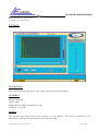
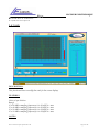
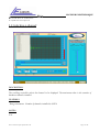
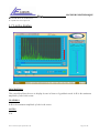
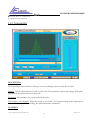
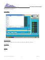
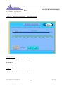
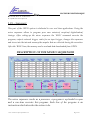
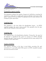
LECOEUR ELECTRONIQUE 19 route de Courtenay - 45220 – CHUELLES – : 02 38 94 28 30– : 02 38 94 29 67 : [email protected] USER’S GUIDE FOR OPEN SYSTEM Rev 1.15 - Mars 2006 – Copyright Lecoeur Electronique corporation all rights reserved - OPEN SYSTEM User's Guide For Open System Rev 1-15 Page 1 sur 80 LECOEUR ELECTRONIQUE 19 route de Courtenay - 45220 – CHUELLES – : 02 38 94 28 30– : 02 38 94 29 67 : [email protected] 1) Using Standard Interface 2) Excel global set-up file description 3) Hardware presentation User's Guide For Open System Rev 1-15 Page 2 sur 80 LECOEUR ELECTRONIQUE 19 route de Courtenay - 45220 – CHUELLES – : 02 38 94 28 30– : 02 38 94 29 67 : [email protected] 1.1 Setting up the number of sequences DESCRIPTION: Each time the application is loaded the first task is to set up the number of sequences to load. The user can enter a number of sequences or hit ‘esc’ to skip. In this case only 8 sequences are loaded. The user can also enter the sampling frequency of receivers analogue to digital converters. FEATURES: N/A NOTES: The sampling frequency will be stored in the current set-up file. User's Guide For Open System Rev 1-15 Page 3 sur 80 LECOEUR ELECTRONIQUE 19 route de Courtenay - 45220 – CHUELLES – : 02 38 94 28 30– : 02 38 94 29 67 : [email protected] 1.2 Gain DESCRIPTION: This controller allows the user to enter a gain value for the selected channel. FEATURES: Range: 0 to 80 dB Step: 0.1 dB Bandwidth: 0.5 MHz to 20 MHz at -6 dB Linearity: -/+ 0.5 dB. NOTES: The reported noise to the input of the receiver is 1 nV/ Sqr(Hz). This value is measured in our laboratories; it doesn’t include connectors and external cables. User's Guide For Open System Rev 1-15 Page 4 sur 80 LECOEUR ELECTRONIQUE 19 route de Courtenay - 45220 – CHUELLES – : 02 38 94 28 30– : 02 38 94 29 67 : [email protected] 1.3 Delay DESCRIPTION: Allows the user to control the delay of the display. IT IS ONLY FOR VISUALISATION. The delays on receivers or transmitter for beam forming are set up in other menu. FEATURES: Unit: µS Range: 0 to 160 µS NOTES: N.A User's Guide For Open System Rev 1-15 Page 5 sur 80 LECOEUR ELECTRONIQUE 19 route de Courtenay - 45220 – CHUELLES – : 02 38 94 28 30– : 02 38 94 29 67 : [email protected] 1.4 Scale DESCRIPTION: This function allows to modify the scale for the screen display. FEATURES: Unit: µS per division Range: -For 80 MHz sampling frequency: 0 to 10 µS/Div. -For 40 MHz sampling frequency: 0 to 20 µS/Div. -For 20 MHz sampling frequency: 0 to 39 µS/Div. -For 10 MHz sampling frequency: 0 to 39 µS/Div. max max max max NOTES: N.A User's Guide For Open System Rev 1-15 Page 6 sur 80 LECOEUR ELECTRONIQUE 19 route de Courtenay - 45220 – CHUELLES – : 02 38 94 28 30– : 02 38 94 29 67 : [email protected] 1.5 Selecting a channel DESCRIPTION: The scrolling controller selects the channel to be displayed. The maximum value is the number of hardware channels installed FEATURES: - Range maximum: Number of channels installed in OPEN NOTES: N.A User's Guide For Open System Rev 1-15 Page 7 sur 80 LECOEUR ELECTRONIQUE 19 route de Courtenay - 45220 – CHUELLES – : 02 38 94 28 30– : 02 38 94 29 67 : [email protected] 1.6 RF/A-scan DESCRIPTION: The menu controls the kind of display High frequency is RF mode, A-scan is rectified mode FEATURES: N.A NOTES: N.A User's Guide For Open System Rev 1-15 Page 8 sur 80 LECOEUR ELECTRONIQUE 19 route de Courtenay - 45220 – CHUELLES – : 02 38 94 28 30– : 02 38 94 29 67 : [email protected] 1.7 Lin/log display DESCRIPTION: This controller allows the user to display A-scan in linear or logarithmic mode. 0 dB is the maximum amplitude of echo in the screen. FEATURES: 0 dB is the maximum amplitude of echo in the screen. NOTES: N.A User's Guide For Open System Rev 1-15 Page 9 sur 80 LECOEUR ELECTRONIQUE 19 route de Courtenay - 45220 – CHUELLES – : 02 38 94 28 30– : 02 38 94 29 67 : [email protected] 1.8 DAC DESCRIPTION: This function is a hardware function. When ON is set up, amplifier is controlled by a time variable tension. It is possible to create any kind of curve to compensate attenuation, or to minimise a selected echo or more. The smoothing option makes an interpolation between the points FEATURES: Range: 0 to 80 dB Depth: 160 µS Step: 0.65 µS NOTES: OPTION: 1 mS depth User's Guide For Open System Rev 1-15 Page 10 sur 80 LECOEUR ELECTRONIQUE 19 route de Courtenay - 45220 – CHUELLES – : 02 38 94 28 30– : 02 38 94 29 67 : [email protected] NO SMOOTHING User's Guide For Open System Rev 1-15 Page 11 sur 80 LECOEUR ELECTRONIQUE 19 route de Courtenay - 45220 – CHUELLES – : 02 38 94 28 30– : 02 38 94 29 67 : [email protected] 1.9 Channel On Off DESCRIPTION: Controls the state of the current channel (On :the channel is activated, OFF : the channel is switched off) FEATURES: N.A NOTES: This parameter is only active for OPEN with analog pulsers User's Guide For Open System Rev 1-15 Page 12 sur 80 LECOEUR ELECTRONIQUE 19 route de Courtenay - 45220 – CHUELLES – : 02 38 94 28 30– : 02 38 94 29 67 : [email protected] 1.10 Rectification mode DESCRIPTION: In A-scan mode it is possible to display only the negative wave or positive or both. FEATURES: N.A NOTES: N.A User's Guide For Open System Rev 1-15 Page 13 sur 80 LECOEUR ELECTRONIQUE 19 route de Courtenay - 45220 – CHUELLES – : 02 38 94 28 30– : 02 38 94 29 67 : [email protected] 1.11 Report DESCRIPTION: This function is a dedicated one. The user can create his own report using Labview tools and can activate it with this button. FEATURES: N.A NOTES: N.A User's Guide For Open System Rev 1-15 Page 14 sur 80 LECOEUR ELECTRONIQUE 19 route de Courtenay - 45220 – CHUELLES – : 02 38 94 28 30– : 02 38 94 29 67 : [email protected] 1.12 Averaging DESCRIPTION: Averaging makes the arithmetic average of a selected number of A-scan. This number is entered in the controller ‘Averring’. This has only effect on the display. FEATURES: Range: 1 to 255 NOTES: OPTION: Hardware averaging 1 to 255, averages signals in real time. User's Guide For Open System Rev 1-15 Page 15 sur 80 LECOEUR ELECTRONIQUE 19 route de Courtenay - 45220 – CHUELLES – : 02 38 94 28 30– : 02 38 94 29 67 : [email protected] 1.13 Wizard DESCRIPTION: Switching Wizard ON allows the user to increase gain to 100 dB. The averaging function is controlled by the system to reduce automatically electronic noise. The gain between 80 dB and 100 dB is a numerical gain. This function is a software one. FEATURES: N.A NOTES: OPTION: Hardware averaging 1 to 255, averages signals in real time. User's Guide For Open System Rev 1-15 Page 16 sur 80 LECOEUR ELECTRONIQUE 19 route de Courtenay - 45220 – CHUELLES – : 02 38 94 28 30– : 02 38 94 29 67 : [email protected] 1.14 Fir DESCRIPTION: The “FIR” is a hardware digital filter which can be set up with the windows “FIR”. It is composed with 8 coefficients. The user must take care of entering the right sampling frequency before adjusting. FEATURES: Low Pass filter 8 coefficients FIR NOTES:N.A User's Guide For Open System Rev 1-15 Page 17 sur 80 LECOEUR ELECTRONIQUE 19 route de Courtenay - 45220 – CHUELLES – : 02 38 94 28 30– : 02 38 94 29 67 : [email protected] 1.15 Transmitter DESCRIPTION: The Transmitter can be pulsed or analogue. In case of analogue pulser only P.R.F is active. Voltage: Can be adjusted from 10 Volts to 230 Volts. This parameter controls the voltage of the pulse generated by the pulser and sent to the probe. Frequency: This parameter sets up the width of the pulse. This channel / All channels: When the switch is in position “All channel voltage and Frequency are sent to all boards of OPEN providing the same transmitters parameters. FEATURES: User's Guide For Open System Rev 1-15 Page 18 sur 80 LECOEUR ELECTRONIQUE 19 route de Courtenay - 45220 – CHUELLES – : 02 38 94 28 30– : 02 38 94 29 67 : [email protected] Tests conditions : - Single probe selected on the back side of OPEN 50 Ohm load (resistive) Width measured at 100 Volts CC / at 50 % of amplitude Falling time at 100 Volts CC / 10 to 90 % of amplitude Voltage accuracy a) Standard transmitters Tolérances Value Min Max 230 V 225 V 235 V 200 V 195 V 205 V 150 V 145 V 155 V 100 V 95 V 105 V 50 V 44 V 56 V 10 V 7V 14 V User's Guide For Open System Rev 1-15 Page 19 sur 80 LECOEUR ELECTRONIQUE 19 route de Courtenay - 45220 – CHUELLES – : 02 38 94 28 30– : 02 38 94 29 67 : [email protected] b) High frequency transmitters (OPTION) Tolérances Value Min Max 230 V 228 V 232 V 200 V 198 V 202 V 150 V 148 V 152 V 100 V 98 V 102 V 50 V 47 V 53 V 10 V 8V 12 V Width accuracy a) Standard transmitters Tolérances Pulse Width à 100 V Z=50 Min Max 15 MHz 26 nS 39 nS 10 MHz 42 nS 58 nS 7,5 MHz 60 nS 72 nS 6 MHz 75 nS 91 nS 5 MHz 90 nS 110 nS 4 MHz 108 nS 132 nS User's Guide For Open System Rev 1-15 Page 20 sur 80 LECOEUR ELECTRONIQUE 19 route de Courtenay - 45220 – CHUELLES – : 02 38 94 28 30– : 02 38 94 29 67 : [email protected] b) High frequency transmitters (OPTION) Tolérances Width voltage compensated Min Max 15 MHz 30 nS 36 nS 10 MHz 47 nS 53 nS 7,5 MHz 62 nS 70 nS 6 MHz 80 nS 86 nS 5 MHz 95 nS 105 nS 4 MHz 120 nS 130 nS Falling time a) Standard transmitters - Typical value: 8 nS b) High frequency transmitters (OPTION) - Typical value: 4 nS User's Guide For Open System Rev 1-15 Page 21 sur 80 LECOEUR ELECTRONIQUE 19 route de Courtenay - 45220 – CHUELLES – : 02 38 94 28 30– : 02 38 94 29 67 : [email protected] Pulse shape a) Standard transmitters 4 MHz excitation / 100 Volts User's Guide For Open System Rev 1-15 Page 22 sur 80 LECOEUR ELECTRONIQUE 19 route de Courtenay - 45220 – CHUELLES – : 02 38 94 28 30– : 02 38 94 29 67 : [email protected] 10 MHz excitation / 100 Volts User's Guide For Open System Rev 1-15 Page 23 sur 80 LECOEUR ELECTRONIQUE 19 route de Courtenay - 45220 – CHUELLES – : 02 38 94 28 30– : 02 38 94 29 67 : [email protected] b) High frequency transmitters (OPTION) Falling edge / 100 Volts User's Guide For Open System Rev 1-15 Page 24 sur 80 LECOEUR ELECTRONIQUE 19 route de Courtenay - 45220 – CHUELLES – : 02 38 94 28 30– : 02 38 94 29 67 : [email protected] P.R.F (repetition Frequency): This parameter controls the rate of the pulser. For example setting 1 KHz will generate pulses every millisecond. - Entering 0.03 KHz switches the system to the “EXTERNAL TRIGGER” mode. In this mode a TTL 5 Volts pulse must be input in the plus called ‘EXTERNAL TRIGGER’. The active edge is positive. - Entering 0.01 KHz switches the system in “SOFT TRIGGER” mode. In this mode the pulser generates pulses only when it is necessary (When a a-scan digitalisation is request). If no request is made on OPEN the pulser is set OFF. FEATURES: Range: 0.3 KHz to 20 KHz depending on scale/delay value NOTES: N.A User's Guide For Open System Rev 1-15 Page 25 sur 80 LECOEUR ELECTRONIQUE 19 route de Courtenay - 45220 – CHUELLES – : 02 38 94 28 30– : 02 38 94 29 67 : [email protected] 1.16 Spectrum DESCRIPTION: Displays the spectrum of the current A-SCAN in the screen FEATURES: N.A NOTES: N.A User's Guide For Open System Rev 1-15 Page 26 sur 80 LECOEUR ELECTRONIQUE 19 route de Courtenay - 45220 – CHUELLES – : 02 38 94 28 30– : 02 38 94 29 67 : [email protected] 1.17 Zoom DESCRIPTION: Provides a larger display of A-SCAN FEATURES: N.A NOTES: N.A User's Guide For Open System Rev 1-15 Page 27 sur 80 LECOEUR ELECTRONIQUE 19 route de Courtenay - 45220 – CHUELLES – : 02 38 94 28 30– : 02 38 94 29 67 : [email protected] 1.18 Print DESCRIPTIONS: The Print button transfers the current screen to a printer FEATURES: N.A NOTES: The black colour is changed to white to reduce ink consumption. User's Guide For Open System Rev 1-15 Page 28 sur 80 LECOEUR ELECTRONIQUE 19 route de Courtenay - 45220 – CHUELLES – : 02 38 94 28 30– : 02 38 94 29 67 : [email protected] 1.19 Config. DESCRIPTION: This function allows the user to copy all parameters from one channel to another or on all channels. This will also copy the delays for transmitters and receivers beam-former files. FEATURES: N.A NOTES: N.A User's Guide For Open System Rev 1-15 Page 29 sur 80 LECOEUR ELECTRONIQUE 19 route de Courtenay - 45220 – CHUELLES – : 02 38 94 28 30– : 02 38 94 29 67 : [email protected] 1.20 Delete DESCRIPTION: Deletes a set-up file previously stored with save function. FEATURES: N.A NOTES: N.A User's Guide For Open System Rev 1-15 Page 30 sur 80 LECOEUR ELECTRONIQUE 19 route de Courtenay - 45220 – CHUELLES – : 02 38 94 28 30– : 02 38 94 29 67 : [email protected] 1.21 Save DESCRIPTION: Saves a set-up of OPEN into a file in order to recall it using ‘RECALL’ function. FEATURES: N.A NOTES: N.A User's Guide For Open System Rev 1-15 Page 31 sur 80 LECOEUR ELECTRONIQUE 19 route de Courtenay - 45220 – CHUELLES – : 02 38 94 28 30– : 02 38 94 29 67 : [email protected] 1.22 Recall sampling frequency DESCRIPTION: This menu is displayed at the beginning after OPEN is run. The value of sampling frequency can be modified at this time. It will be stored in the set-up file and recalled through the recall function FEATURES: N.A NOTES: N.A User's Guide For Open System Rev 1-15 Page 32 sur 80 LECOEUR ELECTRONIQUE 19 route de Courtenay - 45220 – CHUELLES – : 02 38 94 28 30– : 02 38 94 29 67 : [email protected] 1.23 Recall DESCRIPTION: Recalls a previously stored set-up. FEATURES: N.A NOTES: N.A User's Guide For Open System Rev 1-15 Page 33 sur 80 LECOEUR ELECTRONIQUE 19 route de Courtenay - 45220 – CHUELLES – : 02 38 94 28 30– : 02 38 94 29 67 : [email protected] 1.24.1 - Mass Memory DESCRIPTION: Inits one channel of the mass memory FEATURES: NOTES: Only available with the mass memory hardware option. User's Guide For Open System Rev 1-15 Page 34 sur 80 LECOEUR ELECTRONIQUE 19 route de Courtenay - 45220 – CHUELLES – : 02 38 94 28 30– : 02 38 94 29 67 : [email protected] 1.24.2 - All Memories DESCRIPTION: Inits all channels of mass memory. FEATURES: NOTES: Only available with the mass memory hardware option. User's Guide For Open System Rev 1-15 Page 35 sur 80 LECOEUR ELECTRONIQUE 19 route de Courtenay - 45220 – CHUELLES – : 02 38 94 28 30– : 02 38 94 29 67 : [email protected] 1.24.3 – Test Single Memories DESCRIPTION: Tests a single mass memory to check the proper or wrong initialisation of it. FEATURES: NOTES: Only available with the mass memory hardware option. User's Guide For Open System Rev 1-15 Page 36 sur 80 LECOEUR ELECTRONIQUE 19 route de Courtenay - 45220 – CHUELLES – : 02 38 94 28 30– : 02 38 94 29 67 : [email protected] 1.24.4 – Auxiliary DESCRIPTION: Set or rest mass memory manager to record all events. FEATURES: NOTES: Only available with the mass memory hardware option. User's Guide For Open System Rev 1-15 Page 37 sur 80 LECOEUR ELECTRONIQUE 19 route de Courtenay - 45220 – CHUELLES – : 02 38 94 28 30– : 02 38 94 29 67 : [email protected] 1.24.5 – “Enregistrement” (Reccording) DESCRIPTION: Controls the record of data in the mass memory. FEATURES: NOTES: Only available with the mass memory hardware option. User's Guide For Open System Rev 1-15 Page 38 sur 80 LECOEUR ELECTRONIQUE 19 route de Courtenay - 45220 – CHUELLES – : 02 38 94 28 30– : 02 38 94 29 67 : [email protected] 1.25 – Sequencer This part of the OPEN system is dedicated to user real time applications. Using the micro sequencer allows to program your own emission/ reception/ digitalization/ timings. After setting-up the micro sequencer the ‘RUN’ command executes the program, outputs external trigger, waits for an input trigger, changes the sequences and stores into the internal memory the samples that are collected during the execution. After the ‘RUN ’time; the memory can be read and data downloaded from OPEN. DESCRIPTION OF THE MICRO SEQUENCER The micro sequencer works as a processor, a program is up-loaded in open and a run-time executes this program. Each line of the program is an instruction which describes the action to do. User's Guide For Open System Rev 1-15 Page 39 sur 80 LECOEUR ELECTRONIQUE 19 route de Courtenay - 45220 – CHUELLES – : 02 38 94 28 30– : 02 38 94 29 67 : [email protected] Transmitter sequence number This parameter indicates the number of sequence to load before executing the instruction. I f the pulser is analog the sequence indicates a wave form, if the pulser is pulsed it sets up a delay. This parameter has the same value for the 8 channels of the same board. Sampling delay This parameter is the time before the digitalization begins. In OPEN standard interface the unit is micro-second. This parameter has the same value for the 8 channels of the same board. Sampling time The sampling time is the digitalization duration. During this, the signal of all channels is digitalized and stored in memory. In OPEN standard interface the unit is micro-second. This parameter has the same value for the 8 channels of the same board. Sequence duration The sequence duration is the time to wait before executing the next instruction. It is generally called PRF period. In OPEN standard interface the unit is the micro-second. User's Guide For Open System Rev 1-15 Page 40 sur 80 LECOEUR ELECTRONIQUE 19 route de Courtenay - 45220 – CHUELLES – : 02 38 94 28 30– : 02 38 94 29 67 : [email protected] Trigger Out If this parameter is set to one, OPEN system will generate a pulse on the ‘trigger-out’ output, at the beginning of the instruction. This pulse is a TTL one and the duration of this pulse is 50 nS. Trigger In If this parameter is set to one, OPEN system will wait for an input pulse on the ‘Trigger in’ input before executing the instruction. Number of Executions This statement is a loop generator. The instruction will be executed N times. N is the value of the parameter. The minimum value is 1and the maximum is 255 Pulser delay This parameter is only active with the option ‘analog pulser’ of OPEN. The waveform is shifted right in the time base. The value of this shift is the parameter value. In the standard interface the unit is micro–second. This parameter has the same value for the 8 channels of the same board. User's Guide For Open System Rev 1-15 Page 41 sur 80 LECOEUR ELECTRONIQUE 19 route de Courtenay - 45220 – CHUELLES – : 02 38 94 28 30– : 02 38 94 29 67 : [email protected] This screen is a test tool of the sequencer. Trigger in: Simulates a hardware trigger input. Memory address: Selects the part of the memory in which the samples will be stored. Delay law: If 0 is entered the samples of the selected channel are displayed. If the value is different than 0 the samples of the eight channel of one board are returned. The value is the sequence number Run: Executes the program of the sequencer previously up-loaded. Read memory: Reads the memory beginning at the selected address. User's Guide For Open System Rev 1-15 Page 42 sur 80 LECOEUR ELECTRONIQUE 19 route de Courtenay - 45220 – CHUELLES – : 02 38 94 28 30– : 02 38 94 29 67 : [email protected] 1.26 Setup DESCRIPTION: This window is a factory one. In normal conditions the user does not need to use it. FEATURES: N.A NOTES: N.A User's Guide For Open System Rev 1-15 Page 43 sur 80 LECOEUR ELECTRONIQUE 19 route de Courtenay - 45220 – CHUELLES – : 02 38 94 28 30– : 02 38 94 29 67 : [email protected] 1.2.1 - Multi A Scan DESCRIPTION: Displays simultaneously eight a-scans of OPEN system. The slider on the right side; changes the number of the first channel to be displayed FEATURES: N.A NOTES: N.A User's Guide For Open System Rev 1-15 Page 44 sur 80 LECOEUR ELECTRONIQUE 19 route de Courtenay - 45220 – CHUELLES – : 02 38 94 28 30– : 02 38 94 29 67 : [email protected] 1.2.2 – Full Screen DESCRIPTION: Displays simultaneously 32 channels of OPEN. The slider on the right side changes the number of the first channel to be displayed. FEATURES: N.A NOTES: N.A User's Guide For Open System Rev 1-15 Page 45 sur 80 LECOEUR ELECTRONIQUE 19 route de Courtenay - 45220 – CHUELLES – : 02 38 94 28 30– : 02 38 94 29 67 : [email protected] 1.3.1 – Group DESCRIPTION: Switches the display to ‘SUM’ display. The signal displayed is the summation of all signals from all channels. Entering this menu will copy automatically GAIN/SCALE/DELAY from channel 1 to all channels. The sequence number can be modified to see the result of summations using different beam forming laws. FEATURES: N.A NOTES: N.A User's Guide For Open System Rev 1-15 Page 46 sur 80 LECOEUR ELECTRONIQUE 19 route de Courtenay - 45220 – CHUELLES – : 02 38 94 28 30– : 02 38 94 29 67 : [email protected] 1.4. - Imaging DESCRIPTION: Displays a beam formed image composed with the number of active sequences in open. Allows access to 3 sub-menus: - SINGLE B-SCAN FOCUSED B-SCAN CALCULATION TOOLS FEATURES: N.A NOTES: N.A User's Guide For Open System Rev 1-15 Page 47 sur 80 LECOEUR ELECTRONIQUE 19 route de Courtenay - 45220 – CHUELLES – : 02 38 94 28 30– : 02 38 94 29 67 : [email protected] 1.4.1 – Simple B-Scan DESCRIPTION: Displays all channels simultaneously in colour scale. FEATURES: - A-SCAN: The signal coming fro the channel pointed by the vertical cursor is displayed - DISPLAY FREQUENCY: Indicates the refresh rate of the screen. - NUMBER OF CHANNELS: Number of channels installed in OPEN system. - AXIAL RESOLUTION: Sets a compression factor on samples coming from OPEN boards. User's Guide For Open System Rev 1-15 Page 48 sur 80 LECOEUR ELECTRONIQUE 19 route de Courtenay - 45220 – CHUELLES – : 02 38 94 28 30– : 02 38 94 29 67 : [email protected] - SEQUENCE NUMBER: Number of the sequence to be activated. This is only for pulsers delay sequences. - BEST: Makes an interpolation between lines. - DISPLAY LIN/LOG : Sets the display in linear or logarithmic mode. - PALETTE: Displays the palette used for the B-SCAN. Beginning and final colours can be adjusted to change the visualisation. - CALIBRATE: Makes a calibration of 0 for all channels. - AUTOSCALE: Switching off this parameter allows using ZOOM tool located above the auto scale button. NOTES: N.A User's Guide For Open System Rev 1-15 Page 49 sur 80 LECOEUR ELECTRONIQUE 19 route de Courtenay - 45220 – CHUELLES – : 02 38 94 28 30– : 02 38 94 29 67 : [email protected] 1.4.2 – Focused B-Scan DESCRIPTION: Displays focussed B-SCAN composed with the number of active sequences in OPEN. FEATURES: - FOCUSSING DEPH: Indicates the focused point used when delays laws where calculated with the calculation tool - PALETTE: Displays the palette used for the B-SCAN. Beginning and final colours can be adjusted to change the visualisation. - INTERPOLATION: Adds lines to make a better resolution image. User's Guide For Open System Rev 1-15 Page 50 sur 80 LECOEUR ELECTRONIQUE 19 route de Courtenay - 45220 – CHUELLES – : 02 38 94 28 30– : 02 38 94 29 67 : [email protected] - NUMBER OF FOCALISATIONS: It is the number of sequences used to build the image. - ANGLE: Recalls the values of the angles used when delay laws where calculated. NOTES: N.A User's Guide For Open System Rev 1-15 Page 51 sur 80 LECOEUR ELECTRONIQUE 19 route de Courtenay - 45220 – CHUELLES – : 02 38 94 28 30– : 02 38 94 29 67 : [email protected] 1.4.3 – Calculations Tools DESCRIPTION: Simple tool to calculate delays to make a beam formed image. FEATURES: - NUMBER OF ELEMENTS: Number of elements of the probe. - WIDTH OF ELEMENT: The physical width of each element of the probe (in millimetres). User's Guide For Open System Rev 1-15 Page 52 sur 80 LECOEUR ELECTRONIQUE 19 route de Courtenay - 45220 – CHUELLES – : 02 38 94 28 30– : 02 38 94 29 67 : [email protected] - SPACE INTER-ELEMENT: The physical space between of each element of the probe (in millimetres). - VELOCITY: The velocity of ultrasound in the material. - ALPHA: the beginning and ending angles for deflexion. - FOCUSING DEPTH: The distance of focalisation point. - NUMBER OF SEQUENCES: Allows changing the number of sequences actives is OPEN. Validates this choice by pushing ‘APPLY’ button. - NAME OF THE DELAYS FILES: This controller holds the name of the directories that will be created to store the delays files which contain the pulsers and receiver delays for each sequence. To get more information please refer to the Excel file section. The ‘CREATE FILE’ button changes the files and directories names. - DESTROY EXISTING FILES: Destroys the files and directories previously created. - ALL DELAYS TO ZERO: Creates files filled with delays set to value 0. - CALCULATE DELAY LAWS: Generates the delays files. - VIEW IMAGE: Displays the result of the focused image. NOTES: This very simple tool is provided as a test tool. User's Guide For Open System Rev 1-15 Page 53 sur 80 LECOEUR ELECTRONIQUE 19 route de Courtenay - 45220 – CHUELLES – : 02 38 94 28 30– : 02 38 94 29 67 : [email protected] 2. - Matrix DESCRIPTION: Gets access to matrix menus. FEATURES: N.A NOTES: N.A User's Guide For Open System Rev 1-15 Page 54 sur 80 LECOEUR ELECTRONIQUE 19 route de Courtenay - 45220 – CHUELLES – : 02 38 94 28 30– : 02 38 94 29 67 : [email protected] 2.1. – Matrix of Receivers Delays DESCRIPTION: Displays the value of receivers delays applied on each channel for the selected sequence. FEATURES: N.A NOTES: N.A User's Guide For Open System Rev 1-15 Page 55 sur 80 LECOEUR ELECTRONIQUE 19 route de Courtenay - 45220 – CHUELLES – : 02 38 94 28 30– : 02 38 94 29 67 : [email protected] 2.2 – Matrix of Pulser Delay DESCRIPTION: Displays the value of pulsers delays applied on each channel for the selected sequence. FEATURES: N.A NOTES: N.A User's Guide For Open System Rev 1-15 Page 56 sur 80 LECOEUR ELECTRONIQUE 19 route de Courtenay - 45220 – CHUELLES – : 02 38 94 28 30– : 02 38 94 29 67 : [email protected] 2.3 – Matrix of Pulser Width DESCRIPTION: An advanced menu to change the width of pulsers. This menu must not be used before a prior contact with LECOEUR ELECTRONIQUE technical support before. FEATURES: N.A NOTES: N.A User's Guide For Open System Rev 1-15 Page 57 sur 80 LECOEUR ELECTRONIQUE 19 route de Courtenay - 45220 – CHUELLES – : 02 38 94 28 30– : 02 38 94 29 67 : [email protected] 2.4 – Matrix OF Receivers Gain DESCRIPTION: Displays and offers the possibility to change the receivers gains. FEATURES: N.A NOTES: N.A User's Guide For Open System Rev 1-15 Page 58 sur 80 LECOEUR ELECTRONIQUE 19 route de Courtenay - 45220 – CHUELLES – : 02 38 94 28 30– : 02 38 94 29 67 : [email protected] 3 – Excel DESCRIPTION: Gives access to the global set-up file of OPEN. FEATURES: N.A NOTES: N.A User's Guide For Open System Rev 1-15 Page 59 sur 80 LECOEUR ELECTRONIQUE 19 route de Courtenay - 45220 – CHUELLES – : 02 38 94 28 30– : 02 38 94 29 67 : [email protected] 3.1 – Edit Excel File DESCRIPTION: Global set-up file of OPEN. It contains all information about OPEN set-up. Please read the EXCEL FILE section to understand the use of this file. FEATURES: N.A User's Guide For Open System Rev 1-15 Page 60 sur 80 LECOEUR ELECTRONIQUE 19 route de Courtenay - 45220 – CHUELLES – : 02 38 94 28 30– : 02 38 94 29 67 : [email protected] 3.1 – Import Excel File Values DESCRIPTION: Imports the values contained in excel file and set them active in OPEN. FEATURES: NOTES: User's Guide For Open System Rev 1-15 Page 61 sur 80 LECOEUR ELECTRONIQUE 19 route de Courtenay - 45220 – CHUELLES – : 02 38 94 28 30– : 02 38 94 29 67 : [email protected] 4. – Analog Transmitter DESCRIPTION: Gives access to functions for analog transmitter FEATURES: N.A NOTES: Only active with the option ‘analog pulser’ of OPEN system. User's Guide For Open System Rev 1-15 Page 62 sur 80 LECOEUR ELECTRONIQUE 19 route de Courtenay - 45220 – CHUELLES – : 02 38 94 28 30– : 02 38 94 29 67 : [email protected] 4.1 – Name DESCRIPTION: Indicates/Modifies the current active analog pulser waveform for the selected sequence/Channel. FEATURES: N.A NOTES: Only active with the option ‘analog pulser’ of OPEN system. User's Guide For Open System Rev 1-15 Page 63 sur 80 LECOEUR ELECTRONIQUE 19 route de Courtenay - 45220 – CHUELLES – : 02 38 94 28 30– : 02 38 94 29 67 : [email protected] 4.1.1 – Change Emission File DESCRIPTION: Loads a new waveform for the analog pulser. FEATURES: N.A NOTES: Only active with the option ‘analog pulser’ of OPEN system. User's Guide For Open System Rev 1-15 Page 64 sur 80 LECOEUR ELECTRONIQUE 19 route de Courtenay - 45220 – CHUELLES – : 02 38 94 28 30– : 02 38 94 29 67 : [email protected] 4.2 – Tools DESCRIPTION: Gives access to the waveform editor. FEATURES: N.A NOTES: Only active with the option ‘analog pulser’ of OPEN system. User's Guide For Open System Rev 1-15 Page 65 sur 80 LECOEUR ELECTRONIQUE 19 route de Courtenay - 45220 – CHUELLES – : 02 38 94 28 30– : 02 38 94 29 67 : [email protected] 4.2.1 – Edit Transmitter curve DESCRIPTION: Provides an advanced tool to edit/ create/ store/recall transmitter waveforms. FEATURES: N.A NOTES: Only active with the option ‘analog pulser’ of OPEN system. User's Guide For Open System Rev 1-15 Page 66 sur 80 LECOEUR ELECTRONIQUE 19 route de Courtenay - 45220 – CHUELLES – : 02 38 94 28 30– : 02 38 94 29 67 : [email protected] 5. – Imaging DESCRIPTION: Displays information about the analog transmitter and receiver delays FEATURES: NOTES: Futures up-dates of OPEN software will be located in those menus. Only active with the option ‘analog pulser’ of OPEN system. User's Guide For Open System Rev 1-15 Page 67 sur 80 LECOEUR ELECTRONIQUE 19 route de Courtenay - 45220 – CHUELLES – : 02 38 94 28 30– : 02 38 94 29 67 : [email protected] 2) Excel global set-up file description The complete set-up of your OPEN system is contained in an Excel file located in: c:\saphirp\brainscan.xls. Below is the description of this file. 2.1) what’s in brainscan.xls file This section describes the use of parameters inside excel file. User's Guide For Open System Rev 1-15 Page 68 sur 80 LECOEUR ELECTRONIQUE 19 route de Courtenay - 45220 – CHUELLES – : 02 38 94 28 30– : 02 38 94 29 67 : [email protected] The sheet contains in lines the channel number and in rows the parameters. To simplify the description we will only describe the more important parameters. Channel number: The number of the channels in which parameters contained on this line are used to. Type of treatment: OPEN system always work on processing number 7. Receiver gain: Gain of each channel in dB. User's Guide For Open System Rev 1-15 Page 69 sur 80 LECOEUR ELECTRONIQUE 19 route de Courtenay - 45220 – CHUELLES – : 02 38 94 28 30– : 02 38 94 29 67 : [email protected] File in which are delays for pulsers: The file pointed by this cell contains the delays that are applied to pulsers for all sequences. Each channel could have a different pulser delay file. Receivers sampling frequency: Only the first line (in red) is active. The value of this cell is the sampling frequency of all analog to digital converters connected to the receivers. The unit is MHz. User's Guide For Open System Rev 1-15 Page 70 sur 80 LECOEUR ELECTRONIQUE 19 route de Courtenay - 45220 – CHUELLES – : 02 38 94 28 30– : 02 38 94 29 67 : [email protected] File in which are delay for receivers: The file pointed by this cell contains the delays that are applied to receivers for all sequences. Each channel could have a different receiver delay file. Analog pulser waveform sequences: The file pointed by this cell contains the name of waveforms that are applied to analog pulsers for all sequences. Each channel could have a different waveform files. Analog transmitters sampling frequency: Only the first line (in red) is active. The value of this cell is the sampling frequency of all digital to analog converters connected to the analog transmitter to generate waveforms. The unit is MHz. User's Guide For Open System Rev 1-15 Page 71 sur 80 LECOEUR ELECTRONIQUE 19 route de Courtenay - 45220 – CHUELLES – : 02 38 94 28 30– : 02 38 94 29 67 : [email protected] Name of DAC curve: This cell contains the path to the DAC curve applied on the channel. The DAC curve file is a text file that describes the shape of the gain variations. Velocity: The velocity of ultrasound. This parameter is used to convert time in distance in the OPEN standard interface. User's Guide For Open System Rev 1-15 Page 72 sur 80 LECOEUR ELECTRONIQUE 19 route de Courtenay - 45220 – CHUELLES – : 02 38 94 28 30– : 02 38 94 29 67 : [email protected] PRF: The value of repetition pulse frequency P.R.F (repetition Frequency): This parameter controls the rate of the pulser. For example setting 1 KHz will generate pulses every millisecond. - Entering 0.03 KHz switches the system to the “EXTERNAL TRIGGER” mode. In this mode a TTL 5 Volts pulse must be input in the plus called ‘EXTERNAL TRIGGER’. The active edge is positive. - Entering 0.01 KHz switches the system to the “SOFT TRIGGER” mode. In this mode the pulser generates pulses only when it is necessary (When a A-Scan digitalisation is requested). If no request is made on OPEN the pulser is set to OFF. User's Guide For Open System Rev 1-15 Page 73 sur 80 LECOEUR ELECTRONIQUE 19 route de Courtenay - 45220 – CHUELLES – : 02 38 94 28 30– : 02 38 94 29 67 : [email protected] ON/OFF DAC: Setting this value to 0 switches off the DAC curve. Setting 1 activates it. TIME/DIST: Setting this value to 0 indicates to OPEN standard interface that unit is time. Setting it to 1 validates the unit to millimeters. SMOOTH: Current state of the DAC curve. Smoothed ->1 / not smoothed >0. User's Guide For Open System Rev 1-15 Page 74 sur 80 LECOEUR ELECTRONIQUE 19 route de Courtenay - 45220 – CHUELLES – : 02 38 94 28 30– : 02 38 94 29 67 : [email protected] The parameters from ‘SEQUENCER STEP’ to ‘SEQUENCER pulser delay’ are used in the micro sequencer function. Sequencer step This parameter indicates the order in which the program will be executed Step 1, Step 2, etc ... This parameter must not be modified. Sequencer trans seq This parameter indicates the number of sequences to load before executing the instruction. I f the pulser is analog the sequence indicates a wave form, if the pulser is pulsed it sets up a delay. This parameter has the same value for the 8 channels of the same board. Sequencer num delay This parameter is the time before the digitalization begins. In OPEN standard interface the unit is micro-second. This parameter has the same value for the 8 channels of the same board. Sequencer num width The sampling time is the digitalization duration. During this, the signal of all channels is digitalized and stored in memory. In OPEN standard interface the unit is micro-second. This parameter has the same value for the 8 channels of the same board. User's Guide For Open System Rev 1-15 Page 75 sur 80 LECOEUR ELECTRONIQUE 19 route de Courtenay - 45220 – CHUELLES – : 02 38 94 28 30– : 02 38 94 29 67 : [email protected] Sequencer seq time The sequence duration is the time to wait before executing the next instruction. It is usually called the PRF period. In OPEN standard interface the unit is micro-second. Sequencer Trigger Out If this parameter is set to one, OPEN system will generate a pulse on the ‘trigger-out’ output, at the beginning of the instruction. This pulse is a TTL one the duration of this pulse is 50 nS. Sequencer Trigger In If this parameter is set to one, OPEN system will wait for an input pulse on the ‘Trigger in’ input before executing the instruction. Sequencer loop This statement is a loop generator. The instruction will be executed N times. N is the value of the parameter. The minimum value is 1 and the maximum is 255. Sequencer pulser delay This parameter is only active with the option ‘analog pulser’ of OPEN. The waveform is directly shifted into the time base. The value of this shift is the parameter value. In the standard interface the unit is micro–second. This parameter has the same value for the 8 channels of the same board User's Guide For Open System Rev 1-15 Page 76 sur 80 LECOEUR ELECTRONIQUE 19 route de Courtenay - 45220 – CHUELLES – : 02 38 94 28 30– : 02 38 94 29 67 : [email protected] Focalization parameters: Internal use of OPEN software. User's Guide For Open System Rev 1-15 Page 77 sur 80 LECOEUR ELECTRONIQUE 19 route de Courtenay - 45220 – CHUELLES – : 02 38 94 28 30– : 02 38 94 29 67 : [email protected] 3) Hardware presentation FRONT VIEW CLOSED FRONT VIEW OPEN User's Guide For Open System Rev 1-15 Page 78 sur 80 LECOEUR ELECTRONIQUE 19 route de Courtenay - 45220 – CHUELLES – : 02 38 94 28 30– : 02 38 94 29 67 : [email protected] The standard OPEN includes no internal computer, an external PC is connected to the OPEN through a USB2 link. It means that the LEDS and switches are not activated. REAR VIEW - Power 110/220 V: This input is the power supply input. It must be connected to operate. - Trigger in: This is a TTL input; the maximum voltage is 5 Volts. It is used to synchronize OPEN with external equipments. - Trigger Out: This is a 5 Volts TTL output to synchronize other equipments from OPEN. It usually generates pulses 0-5 Volts 50 nS width. - Single / dual probe : This is a switch. In ‘dual’ probe position the user needs to connect two probes to OPEN: One is the transmitter probe the other User's Guide For Open System Rev 1-15 Page 79 sur 80 LECOEUR ELECTRONIQUE 19 route de Courtenay - 45220 – CHUELLES – : 02 38 94 28 30– : 02 38 94 29 67 : [email protected] one is the receiver. In ‘single probe’ position only one probe does both transmission and reception. - Probes: Two sockets where probes must be connected. If OPEN works in single probe the probe can be connected in ‘TRANSMITTER’ or ‘RECEIVER’ User's Guide For Open System Rev 1-15 Page 80 sur 80