1
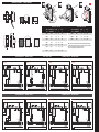
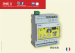
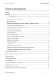
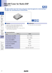
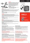
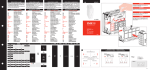
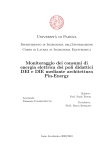
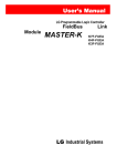
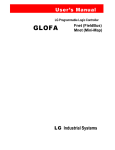
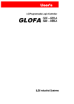
RD1A
1
DESCRIZIONE FRONTALE
9
➊ Setting intervention threshold IΔ n 1
➋ Range selector x1 / x10 / x100
➊ Predisposizione IΔ n soglia d’intervento 1
➋ Selettore portata x1 / x10 / x100
4
1
7 8
6
RD3A
1
4
x1
x10
x100
IΔ n
2
3
9
2
3
Trip
0,03...0,3A
1
0,3...3A
3...30A
Sorveglianza • Supervision
✺
✺
•✺•✺
Interruzione collegamento toroide - relè
Connection breakdown between relay and ring current transformer
RD1D
•
✺
•✺•✺
7
9
RD1E
2
4
6
5
10
1
9
(t = 0 )
7
3
8
LED off
LED on
LED blinking
Test key
It allows to simulate alarm condition, LED Trip switching on and output relay
switching.
➏ Reset key
➐ Automatic-manual reset switch
Man (manual) = the alarm stays until the operator doesn’t act on RESET key
Aut (automatic) = when alarm occurred, this unit automatically resets, making
some attempts.
When attempts are over, if the device didn’t reset, the meter enters the definiti
ve alarm state and it has to be manually reset.
The simultaneous blinking of the three yellow LED’s signals that reset attempts
are over.
CODICE • CODE
N° TENTATIVI /INTERVALLO TEMPO • NUMBER OF ATTEMPTS / TIME INTERVAL
RD1A - RD1D - RD3AF
3/60S
RD3AT
5/10S
ISTRUZIONI DI CABLAGGIO
• La posizione di fissaggio risulta completamente indifferente ai fini del funzionamento.
• Le operazioni di predisposizione (soglia intervento, tempo ritardo, ecc.) devono
essere effettuate con apparecchio non alimentato.
• Rispettare scrupolosamente lo schema d'inserzione, una inesattezza nei collegamenti è ineviitabilmente causa di funzionamento anomalo o di danni all'apparecchio.
• L'ottenimento della piena funzionalità del sistema di protezione differenziale è legato alle modalità di installazione, per cui si consiglia:
☞ Ridurre al minimo la distanza tra toroide e relè
☞ Utilizzare cavi schermati o intrecciati per la loro connessione
☞ Evitare di disporre i cavetti di connessione toroide-relè parallelamente a conduttori
di potenza
☞ Evitare di installare toroide e relè in prossimità di sorgenti di campi elettromagneti
ci intensi (grossi trasformatori).
☞ Solo i conduttori attivi attraversano il toroide (dis.D1)
☞ Utilizzando cavo schermato, l’armatura deve essere collegata a terra come da
(dis.D2)
☞ I conduttori devono essere posizionati al centro del toroide (dis.D3).
■
5
3
ISTRUMENTI MISURE ELETTRICHE SpA
Cod. RD...
ISTRUMENTI MISURE ELETTRICHE SpA
➎
Ne (norm. eccitato) sicurezza positiva.
Il relè di preallarme è sempre norm. diseccitato (mod. RD1E).
➒ Predisposizione ritardo intervento
ATTENZIONE ! Selezionando la soglia d’intervento
nella posizione 0,03 viene automaticamente escluso il ritardo
intervento, indipendentemente dalla posizione del selettore di portata ➋.
Per predisporre soglia di intervento IΔ n = 30mA con intervento istantaneo
selezionare 0,03 e accertarsi che il selettore ➋ sia in posizione x1.
➓ Indicazione istantanea della corrente differenziale (in % del valore IΔ n impostato).
2
(t = 0 )
8
Istruzioni d’uso
User’s Guide
Allarme • Alarm
➑ Selettore stato relé uscita: Nd (norm. diseccitato) sicurezza negativa -
6
Check that selected intervention value matches the lowest sensibility detecta ble by the connected ring current transformer.
➌ • ➍ Signaling LED
•
✺
Il ripristino è inibito con corrente differenziale persistente: ≅ 50% IΔ n impostata
4
0,3
300mA
3A
30A
Model RD1E has a pre-alarm relay with fixed intervention threshold equal to
50% of selected IΔ n value .
Assenza tensione alimentazione ausiliaria o apparecchio fuori servizio
Lack of auxiliary voltage supply or out of order meter
RD3AU
1
0,2
200mA
2A
20A
•
Permette di simulare la condizione di allarme, l’accensione del LED Trip e la
commutazione del relè d’uscita.
➏ Pulsante di ripristino
➐ Selettore ripristino
Man (manuale) = lo stato di allarme permane fino a quando l’operatorenon agisce sul tasto RESET
Aut (automatico) = ad allarme intervenuto, l’apparecchio provvede automaticamente al ripristino, facendo alcuni tentativi.
Terminati i tentativi, se il dispositivo non si è ripristinato, l’apparecchio entra in
stato di allarme definitivo e deve essere ripristinato manualmente.
Il lampeggio contemporaneo dei tre LED gialli, segnala l’esaurimento dei tentati
vi di ripristino.
5
0,15
150mA
1,5A
15A
•
✺
➎ Pulsante di prova
Test
6 7
0,1
100mA
1A
10A
Trip / Fail
LED spento
LED acceso
LED lampeggiante
20
10 8
0,075
75mA
750mA
7,5A
On
40
Reset
0,05
50mA
500mA
5A
Il modello RD1E è dotato di un relè di preallarme con soglia intervento fissa,
pari al 50% del valore di IΔ n selezionato .
60
%
0,03
30mA
300mA
3A
Controllare che il valore d’intervento selezionato sia compatibile con le sensibilità minima rilevabile dal trasformatore toroidale abbinato.
➌ • ➍ LED segnalazione
5
10781265
FRONT DESCRIPTION
1/10S
Reset is not possible with persistent residual current: ≅ 50% IΔ n.
➑ Switch for state of output relay: Nd (normally de-energised) negative security
Ne (normally energised) positive security.
Pre-alarm relay is always normally de-energized (mod. RD1E).
➒ Setting intervention delay
ATTENTION ! Selecting the intervention threshold
on position 0,03 the intervention delay
is automatically excluded, independently of position of range selector ➋.
To set intervention threshold IΔ n = 30mA with istantaneous intervention,
select 0,03 and make sure that selector ➋ is on position x1.
➓ Instantaneous display of earth leakage current (in % of loaded IΔ n value)
INSTRUCTIONS FOR WIRING
• Mounting position do not affect in any way the proper working.
• Setting operations (intervention threshold, delay time, etc.) must be carried
out with non-fed meter.
• Please carefully follow the wiring diagram; an error in connecting the relay may give
rise to irregular working or damages.
• The achievement of differential protection system full functionality is bound to the
mounting way;therefore we suggest:
☞ To reduce as much as possible the distance between ring current transformer
and relay.
☞ To use only shielded or twisted cables for their connection
☞ To avoid in placing ring current transformer-relay connection cables parallelly to
power wires
☞ To avoid in mounting ring current transformer and relay near sources of intense electromagnetic fields (big transformers).
☞ Pass active conductor only through toroid (draw D1)
☞ When using blind cable, ensure ground connection of armature (draw D2)
☞ Ensure the central positioning of conductor through toroid (draw D3).
■
ISTRUMENTI MISURE ELETTRICHE SpA
Via Travaglia 7
20094 CORSICO (MI)
ITALIA
Tel. 02 44 878.1
Fax 02 45 03 448
+39 02 45 86 76 63
www.imeitaly.com
[email protected]
03/10
DIMENSIONE DI INGOMBRO • OVERALL DIMENSIONS
D1
D2
D3
X=Y=Z
X
L1
52
L3
L2
Y
N
L3
L1
48
45
N
L2
52
Z
PE
102
48
45
NUCLEO CHIUSO / CLOSED CORE
75
72
68
75
(1)
CODICE
PASSAGGIO CAVO
IΔn min
CODE
PASSING CABLE
TDGA2
NUCLEO APRIBILE / OPEN CORE
A
In
A
Imax
A
Ø 28
0,03
65
TDGB2
Ø 35
0,03
TDGH2
Ø 60
TDGC2
(2)
CODICE
PASSAGGIO CAVO
IΔn min(1)
A
In
A
Imax(2)
A
CODE
PASSING CABLE
390
TDAA2
Ø 110
0,5
250
1500
70
420
TDAB2
Ø 150
0,5
250
1500
0,03
90
540
TDAC2
Ø 300
1
630
3780
Ø 80
0,05
170
1020
TDGD2
Ø 110
0,1
250
1500
TDGE2
Ø 140
0,3
250
1500
TDGF2
Ø 210
0,3
400
2400
(1)
68
A
72
SICUREZZA NEGATIVA • NEGATIVE SECURITY
S 291/97
S 291/96
AUX.SUPPLY
(+) (-)
20
21
RD1A • RD3A • RD1D
RESET TEST
19 18 17
6
4
TRANSFORMER
3 2
1
RESET
19 18 17
4
TEST
6
TRANSFORMER
Ba
B A
19 18 17 60 61 62
RESET TEST
4
6
TRANSFORMER
3 2
1
6
4
3 2
1
TRIP
RESET TEST
19 18 17 60 61 62 4
6
TRANSFORMER
3 2
1
Ba
L1
L2
L3
N
4
6
TRANSFORMER
3 2
1
Ba
B A
TD
L1
L2
L3
N
SICUREZZA POSITIVA • POSITIVE SECURITY
AUX.SUPPLY
(+) (-)
20
21
B A
S 291/99
TRIP
50%
19 18 17 60 61 62
RESET TEST
4
6
TRANSFORMER
3 2
1
50%
19 18 17 60 61 62
RESET TEST
4
6
TRANSFORMER
3 2
1
Ba
TD
L1
L2
L3
N
TRIP
AUX.SUPPLY
(+) (-)
20
21
B A
Bm
TD
TD
19 18 17
TEST
TD
RD1E
50%
RESET
AUX.SUPPLY
(+) (-)
20
21
B A
S 291/102
AUX.SUPPLY
(+) (-)
20
21
B A
Bm
19 18 17
TRANSFORMER
L1
L2
L3
N
S 291/101
50%
RESET TEST
TD
S 291/100
TRIP
S 291/95
Bm
L1
L2
L3
N
SICUREZZA NEGATIVA • NEGATIVE SECURITY
L1
L2
L3
N
AUX.SUPPLY
(+) (-)
20
21
3 2
1
TD
L1
L2
L3
N
AUX.SUPPLY
(+) (-)
20
21
SICUREZZA POSITIVA • POSITIVE SECURITY
S 291/98
AUX.SUPPLY
(+) (-)
20
21
B A
Bm
Minima corrente IΔn valore minimo di IΔn impostabile sul relè differenziale abbinato al toroide
IΔn lowest current IΔn lowest value that can be set on earth leakage relay connected with toroid
(2)
Corrente di test corrispondente a 6In: Imax (EN 60947-2 annex M)
Test current corresponding to 6In: Imax (EN 60947-2 annex M)
B A
TD
L1
L2
L3
N