1
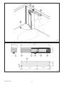
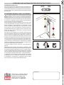
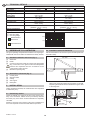
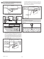
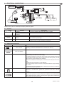
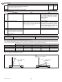
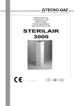
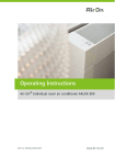
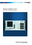
SPRINT
IP1546 - rev. 2007-12-12
I
GB
F
D
E
P
DITEC S.p.A.
Via Mons. Banfi, 3 - 21042 Caronno Pertusella (VA)
Distribuzione: DONATI SRL via Ponchielli 2Cernusco s/N MI - Italy
tel +39 02 9240133 Fax +39 02 9240135 www.donati.it - [email protected]
Manuale di installazione
e manutenzione per
automazioni per porte
battenti.
Installation and
maintenance manual for
automations for swing
doors.
Manuel d’installation et
d’entretien pour portes
battantes.
Montage und
Wartungshandbuch für
Drehtürenantrieb.
Manual de instalaciòn y
manutenciòn para puertas
de vaivén.
Manual de instalação e
manutenção para portas
de balanço.
1
2
2
2x
4x
1.5
0.5
mm 2
mm 2
3
4
Fig. 1
450
80
90
7
7
1
8
5
6
8
60
9
8
260
168
8
Fig. 2
SPRINT - IP1546
2
AVVERTENZE GENERALI PER LA SICUREZZA
DIRETTIVA MACCHINE
Il presente manuale di installazione è rivolto esclusivamente
a personale professionalmente competente.
L’installazione, i collegamenti elettrici e le regolazioni devono
essere effettuati nell’osservanza della Buona Tecnica e in
ottemperanza alle norme vigenti.
Leggere attentamente le istruzioni prima di iniziare l’installazione
del prodotto.
Una errata installazione può essere fonte di pericolo. I materiali
dell’imballaggio (plastica, polistirolo, ecc.) non vanno dispersi
nell’ambiente e non devono essere lasciati alla portata dei
bambini in quanto potenziali fonti di pericolo.
Prima di iniziare l’installazione verificare l’integrità del
prodotto.
Non installare il prodotto in ambiente e atmosfera esplosivi:
presenza di gas o fumi infiammabili costituiscono un grave
pericolo per la sicurezza.
Prima di installare la motorizzazione, apportare tutte le modifiche
strutturali relative alla realizzazione dei franchi di sicurezza ed
alla protezione o segregazione di tutte le zone di schiacciamento,
cesoiamento, convogliamento e di pericolo in genere.
Verificare che la struttura esistente abbia i necessari requisiti
di robustezza e stabilità. Il costruttore della motorizzazione
non è responsabile dell’inosservanza della Buona Tecnica
nella costruzione degli infissi da motorizzare, nonché delle
deformazioni che dovessero intervenire nell’utilizzo. I dispositivi
di sicurezza (fotocellule, coste sensibili, stop di emergenza, ecc.)
devono essere installati tenendo in considerazione: le normative
e le direttive in vigore, i criteri della Buona Tecnica, l’ambiente di
installazione, la logica di funzionamento del sistema e le forze
sviluppate dalla porta o cancello motorizzati.
I dispositivi di sicurezza devono proteggere eventuali zone di
schiacciamento, cesoiamento, convogliamento e di pericolo in
genere, della porta o cancello motorizzati.
Applicare le segnalazioni previste dalle norme vigenti per individuare le zone pericolose.
Ogni installazione deve avere visibile l’indicazione dei dati
identificativi della porta o cancello motorizzati.
Prima di collegare l’alimentazione elettrica accertarsi che
i dati di targa siano rispondenti a quelli della rete di distribuzione elettrica. Prevedere sulla rete di alimentazione un
interruttore/sezionatore onnipolare con distanza d’apertura dei
contatti uguale o superiore a 3 mm.
Verificare che a monte dell’impianto elettrico vi sia un interruttore differenziale e una protezione di sovracorrente adeguati.
Quando richiesto, collegare la porta o cancello motorizzati ad
un efficace impianto di messa a terra eseguito come indicato
dalle vigenti norme di sicurezza.
Durante gli interventi di installazione, manutenzione e riparazione, togliere l’alimentazione prima di aprire il coperchio per
accedere alle parti elettriche.
La manipolazione delle parti elettroniche deve essere
effetuata munendosi di bracciali conduttivi antistatici collegati a terra. Il costruttore della motorizzazione declina ogni
responsabilità qualora vengano installati componenti incompatibili ai fini della sicurezza e del buon funzionamento.
Per l’eventuale riparazione o sostituzione dei prodotti dovranno
essere utilizzati esclusivamente ricambi originali.
L’installatore deve fornire tutte le informazioni relative al funzionamento automatico, manuale e di emergenza della porta o
cancello motorizzati, e consegnare all’utilizzatore dell’impianto
le istruzioni d’uso.
Ai sensi della Direttiva Macchine (98/37/CE) l’installatore che
motorizza una porta o un cancello ha gli stessi obblighi del costruttore di una macchina e come tale deve:
- predisporre il fascicolo tecnico che dovrà contenere i documenti indicati nell’Allegato V della Direttiva Macchine;
(Il fascicolo tecnico deve essere conservato e tenuto a disposizione delle autorità nazionali competenti per almeno dieci
anni a decorrere dalla data di costruzione della porta motorizzata);
- redigere la dichiarazione CE di conformità secondo l’Allegato
II-A della Direttiva Macchine e consegnarla al cliente;
- apporre la marcatura CE sulla porta motorizzata ai sensi del
punto 1.7.3 dell’Allegato I della Direttiva Macchine.
Per maggiori informazioni consultare le “Linee guida per la
realizzazione del fascicolo tecnico” disponibile su internet al
seguente indirizzo: www.ditec.it
INDICAZIONI DI UTILIZZO
Classe di servizio: 5 (minimo 5 anni di utilizzo con 600 cicli
al giorno)
Utilizzo: MOLTO INTENSO (per ingressi di tipo collettivo con
uso carraio o pedonale molto intenso)
- Le prestazioni di utilizzo si riferiscono al peso raccomandato
(circa 2/3 del peso massimo consentito). L’utilizzo con il peso
massimo consentito potrebbe ridurre le prestazioni sopra indicate.
- La classe di servizio, i tempi di utilizzo e il numero di cicli
consecutivi hanno valore indicativo. Sono rilevati statisticamente in condizioni medie di utilizzo e non possono essere
certi per ogni singolo caso. Si riferiscono al periodo nel quale
il prodotto funziona senza necessità di manutenzione straordinaria.
- Ogni ingresso automatico presenta elementi variabili quali:
attriti, bilanciature e condizioni ambientali che possono modificare in maniera sostanziale sia la durata che la qualità di
funzionamento dell’ingresso automatico o di parte dei suoi
componenti (fra i quali gli automatismi). E’ compito dell’installatore adottare coefficienti di sicurezza adeguati ad ogni
particolare installazione.
DICHIARAZIONE DEL FABBRICANTE
(Direttiva 98/37/CE, Allegato II, parte B)
Fabbricante:
DITEC S.p.A.
Indirizzo:
via Mons. Banfi, 3 - 21042
Caronno P.lla (VA) - ITALY
Dichiara che l’automazione per porte battenti serie SPRINT
- è costruito per essere incorporato in una macchina o per
essere assemblato con altri macchinari per costituire una
macchina considerata dalla Direttiva 98/37/CE;
- è conforme alle condizioni delle seguenti altre direttive CE:
Direttiva compatibilità elettromagnetica 89/336/CEE;
Direttiva bassa tensione 73/23/CEE;
e inoltre dichiara che non è consentito mettere in servizio il
macchinario fino a che la macchina in cui sarà incorporata o
di cui diverrà componente sia stata identificata e ne sia stata
dichiarata la conformità alle condizioni della Direttiva 98/37/CE
e alla legislazione nazionale che la traspone.
Caronno Pertusella,
26-01-1998
3
Fermo Bressanini
(Presidente)
SPRINT - IP1546
I
1.
DATI TECNICI
Alimentazione
Assorbimento
Coppia
Tempo di apertura e
di chiusura
Intermittenza
Alimentazione accessori
Tipo di funzionamento
Temperatura
Grado di protezione
Quadro elettronico
Indicazioni di utilizzo
m = lunghezza anta
kg = peso anta
SPRINT
230 V~ / 50-60 Hz
0,2 A
25 Nm
min 7 s / 90°
max 3 s / 90°
S2 = 30 min
S3 = 80%
24 V= / 0,15 A
Apertura a motore
Chiusura a motore
-20 °C / +55 °C
[batterie: +10 °C / +50 °C]
IP12D
165
SPRINTJ
120 V~ / 60 Hz
0,4 A
25 Nm
min 7 s / 90°
max 3 s / 90°
S2 = 30 min
S3 = 80%
24 V= / 0,15 A
Apertura a motore
Chiusura a motore
-20 °C / +55 °C
[batterie: +10 °C / +50 °C]
IP12D
165
150 kg
100 kg
Dimensioni
raccomandate
50 kg
Dimensioni
limite
2.
0,5
RIFERIMENTI ILLUSTRAZIONI
1
1,5 m
3.2 Installazione con braccio articolato
Usare il braccio articolato per porte che aprono all’esterno vista
lato automazione.
La garanzia di funzionamento e le prestazioni dichiarate si ottengono solo con accessori e dispositivi di sicurezza DITEC.
min 550
2.1 Riferimenti installazione tipo (fig. 1)
[1]
[2]
[3]
[4]
Motoriduttore
Radar
Collegare all’alimentazione tramite l’apposita spina. Il collegamento alla rete deve avvenire su canala indipendente
e separata dai collegamenti ai dispositivi di comando e
sicurezza.
Battuta meccanica di apertura
2.2 Riferimenti automazione (fig. 2)
[5]
[6]
[7]
[8]
[9]
Quadro elettronico
Interruttore di accensione/spegnimento
Carter
Supporto bracci
Piastra di base
3.
INSTALLAZIONE
-
Tutte le misure riportate sono espresse in mm, salvo diversa
indicazione.
Togliere il carter e fissare l’automazione a parete rispettando le misure indicate in figura: fare riferimento all’asse
cerniere.
Controllare la stabilità, il peso dell’anta e che il movimento
sia regolare e senza attriti (se necessario rinforzare il telaio).
Eventuali “chiudi porta” devono essere eliminati o, in alternativa,
completamente annullati.
Attenzione: verificare il corretto funzionamento nei casi di installazione su porte che dividono ambienti a pressioni diverse.
SPRINT - IP1546
max 30
3.1 Controlli preliminari
44
I
OPEN
max 300
4
B
-
3.3 Installazione con braccio scorrevole
Assemblare il braccio articolato, senza serrare le viti di
escursione [A], e fissarlo all’automazione facendo attenzione che si inserisca nella sede del supporto bracci.
B
Usare il braccio scorrevole per porte che aprono all’interno vista lato automazione.
A
min 650
-
Fissare la staffa [B] alla porta.
Togliere il carter e fissare l’automazione a parete rispettando le misure indicate in figura: fare riferimento all’asse
cerniere.
B
29 34
44
max 45
46
320
OPEN
Con porta chiusa eseguire la regolazione del braccio e
serrare le viti [A].
-
Forare la guida [C] e fissarla alla porta.
C
B
34
-
C
90-100°
500
A
-
150
Inserire il pattino [D] del braccio scorrevole nella guida
[C]. Fissare il braccio all’automazione facendo attenzione
che si inserisca nella sede del supporto bracci.
Inserire il coperchio [E] e le due testate [F].
F
C
D
F
min 10°
E
5
SPRINT - IP1546
I
3.4 Installazione con braccio articolato SPRINTBRAS
-
Usare il braccio articolato SPRINTBRAS per porte che aprono
verso l’interno vista lato automazione.
min 650
Per distanze comprese tra 45 mm e 20 mm togliere il
braccio [F] e fissare il braccio [G] alla staffa [E] con il distanziale e la vite in dotazione, in modo da formare sempre un angolo compreso tra 80÷90° rispetto al braccio
[M].
E
M
G
max 45
min 650
340
80-90°
-
La distanza di fissaggio dell’automatismo rispetto all’anta
può essere compresa tra 185 mm e 45 mm.
max 45
74
34
220
74
OPEN
3.5 Installazione fermo porta
OPEN
Fissare a pavimento il fermo porta in dotazione come battuta
meccanica in apertura.
34
max 185
250
340
-
Regolare la lunghezza dei bracci [E] ed [F] in modo da
formare un angolo di 80÷90° rispetto al braccio [M], a porta
chiusa.
N.B.: il braccio articolato SPRINTBRAS è assemblato per
anta con apertura a sinistra, nel caso di anta con apertura a
destra, separare il braccio [G] dal braccio [M] (rimuovendo
la spina) e riassemblare i due bracci ruotati di 180°.
min 650
340
E
max 185
I
M
F
G
80-90°
max 395
SPRINT - IP1546
6
COLLEGAMENTI ELETTRICI
BATTERY
12V / 1.2Ah
I
Fuse 5A
TC
T1
VM
T2
15 0 1 2 3 8 9
C
EN
+M - M
ON
+B - B
TRANSF
1 2 3 4
4.
POWER
ALARM
M=
Alimentazione
Power supply
T1-T2
- Uscita / Output
+ 24 V= / 0.15 A
RADAR
RADAR
165
Attenzione: ponticellare tutti i contatti N.C. se non utilizzati.
4.1 Comandi
1
Comando
2
N.O.
1
1
3
8
N.O.
N.C.
1
9
N.C.
Funzione
CHIUSURA
CHIUSURA
AUTOMATICA
APERTURA
SICUREZZA
DI INVERSIONE
STOP
Descrizione
La chiusura del contatto attiva la manovra di chiusura.
Un contatto permanente abilita la chiusura automatica.
La chiusura del contatto attiva la manovra di apertura.
L’apertura del contatto provoca l’inversione del movimento (riapertura)
durante la fase di chiusura.
L’apertura del contatto provoca l’arresto di qualsiasi movimento e l’esclusione di ogni funzione normale o di emergenza.
4.2 Uscite e accessori
Uscita
1
0
Valore
+
-
24 V= / 0,15 A
Descrizione
Alimentazione accessori. Uscita per alimentazione accessori esterni (compresi accessori collegati ai connettori T1 e T2).
Elettroserratura.
0
15
+B -B
T1-T2
12 V / 1,2 A (max)
12 V / 1,2 Ah
Kit batterie. L’automazione è dotata di batteria che garantisce il funzionamento in modo continuità anche in mancanza di rete.
Per caricare le batterie, collegare la rete e le batterie almeno 30 min prima di
avviare l’impianto. Per disalimentare il quadro elettronico si deve togliere l’alimentazione e scollegare le batterie.
Attenzione: per consentire la ricarica, le batterie devono essere sempre collegate al quadro elettronico.
Verificare periodicamente l’efficienza della batteria.
N.B.: la temperatura di funzionamento delle batterie ricaricabili è di circa
+5°C/+40°C.
Per garantire il corretto funzionamento del prodotto è opportuno installare le
batterie all’interno di ambienti climatizzati.
Connettori per collegamento di accessori di comando esterni (esempio: radar RER).
Attenzione: per l’utilizzo di radar RER posizionare il dip-switch del radar in
posizione DX.
Interruttore ON-OFF. Interruttore di accensione/spegnimento. All’accensione
(posizione ON) la prima manovra viene eseguita con acquisizione delle quote
di battuta. Allo spegnimento (posizione OFF) l’alimentazione di linea e le batterie sono scollegate da quadro elettronico.
7
SPRINT - IP1546
I
4.3 Trimmer
TC
VM
Descrizione
Tempo chiusura automatica. Regola il tempo che intercorre tra la fine della manovra di apertura
e l’inizio della chiusura automatica.
N.B.: con DIP1=ON impostare TC>5 s.
Regolazione velocità di apertura e chiusura.
MIN.
MAX.
0s
30 s
7 s/90°
3 s/90°
4.4 Dip-Switch
Descrizione
DIP1 Forza di azionamento.
Normale. [25 Nm]
DIP2 Funzione elettroserratura.
OFF
Con automazione chiusa è presente una
corrente di spinta permanente. L’impulso
di azionamento viene dato contemporaneamente alla partenza della manovra di
apertura.
DIP3 Push&Go.
Disabilitato.
Apertura a sinistra.
DIP4 Selezione senso di marcia.
Il senso di apertura va considerato
guardando l’automazione dal lato
ispezionabile.
ON
Low energy. [16 Nm]
N.B.: per utilizzare l’automazione in condizioni di massima sicurezza (esempio:
passaggio disabili):
- impostare TC>5 s
- impostare VM=5 s/90°
Con automazione chiusa prima della
manovra di apertura viene introdotta una
spinta in chiusura contemporaneamente
all’impulso di azionamento.
Durante la manovra di chiusura la velocità aumenta leggermente per garanrire la
corretta chiusura dell’elettroserratura.
Abilitato.
Apertura a destra.
4.5 Segnalazioni
LED
POWER ALARM
Acceso
Presenza di alimentazione 24 V=.
Lampeggiante
Anomalia encoder / automazione.
4.6 Requisiti delle porte per passaggio disabili
Se l’automazione SPRINT viene utilizzata su porte per passaggio disabili, regolare il trimmer VM in modo che i tempi di apertura
e chiusura (escluso rallentamento) siano uguali o superiori a quelli indicati in tabella.
Lunghezza anta
750 mm
850 mm
1000 mm
1200 mm
50 kg
3,0 s
3,1 s
3,2 s
3,8 s
Peso anta
70 kg
3,2 s
3,2 s
3,7 s
4,5 s
60 kg
3,1 s
3,1 s
3,4 s
4,2 s
80 kg
3,3 s
3,4 s
4,0 s
4,8 s
90 kg
3,5 s
3,6 s
4,2 s
5,1 s
Effettuare inoltre le regolazioni indicate in figura:
APERTURA
Attendere ≥ 5 s - Regolare TC
t ≥ 4s
t ≥ 3s (vedere tabella)
regolare VM
t ≥ 3s (vedere tabella)
regolare VM
~80°
SPRINT - IP1546
CHIUSURA
10° min
8
t ≥ 1,5s
5.
5.1
5.2
5.3
5.4
5.5
5.6
5.7
5.8
5.9
6.
AVVIAMENTO
Attenzione: le manovre relative al punto 5.4 avvengono senza sicurezze.
E’ possibile regolare i trimmer solo ad automazione ferma.
Impostare DIP1 in funzione del tipo di forza da impostare, DIP2 in funzione dell’elettroserratura installata, DIP3=OFF e DIP4
in funzione del senso di apertura.
Regolare il trimmer VM a 1/4 di rotazione e TC al massimo.
Ponticellare le sicurezze (1-8, 1-9).
Dare alimentazione e con successivi comandi 1-2 e 1-3 verificare il corretto funzionamento dell’automazione. Regolare con
il trimmer VM la velocità dell’automazione.
Attenzione: ad ogni accensione il primo movimento di apertura o chiusura viene eseguito a bassa velocità e permette l’apprendimento delle quote di battuta (acquisizione).
Valutare i rischi presenti, installare e collegare al quadro elettronico tutti i dispositivi di sicurezza necessari (1-8, 1-9), e verificarne il funzionamento.
Se desiderato, regolare con TC la chiusura automatica (ponticellare contatto 1-2).
Se si desidera l’apertura Push&Go, impostare DIP3=ON.
Attenzione: la funzione Push&Go non può essere abilitata se DIP2=ON.
Collegare gli eventuali accessori e verificarne il funzionamento.
Se l’automazione incontra un ostacolo durante la corsa di chiusura, lo rileva e si riapre. Se incontra un ostacolo durante la corsa di apertura,
lo rileva e si arresta. Nelle manovre successive, l’ostacolo viene considerato come nuova battuta di arresto fino a quando non viene rimosso.
RICERCA GUASTI
Problema
Possibile causa
L’automazione non apre e non Manca alimentazione.
chiude.
Accessori in corto circuito.
Intervento
Verificare che il quadro elettrico sia alimentato.
(led POWER ALARM acceso).
Scollegare tutti gli accessori dai morsetti 0-1
(deve essere presente tensione 24V=) e ricollegarli uno alla volta.
Contatto di STOP aperto.
Verificare il morsetto 9 del quadro elettronico.
La porta è bloccata da chiavistelli e serrature. Verificare che l’anta si muova liberamente.
Verificare il morsetto 8 del quadro elettronico.
La porta apre ma non chiude. I contatti di sicurezza sono aperti.
I dispositivi di sicurezza sono attivati.
Verificare la pulizia e il corretto funzionamento
delle fotocellule e dei dispositivi di sicurezza.
I radar sono attivati.
Verificare che il radar non sia soggetto a vibrazioni, non esegua false rilevazioni oppure la presenza di corpi in movimento nel suo raggio di azione.
La chiusura automatica non funziona.
Verificare il ponte 1-2.
La porta si apre da sola.
I radar sono instabili oppure rilevano corpi in Verificare che il radar non sia soggetto a vibraziomovimento.
ni, non esegua false rilevazioni oppure la presenza di corpi in movimento nel suo raggio di azione.
La porta apre/chiude per un Encoder guasto.
Sostituire encoder.
breve tratto e poi si ferma.
(led POWER ALARM lampeggiante).
Fili motore invertiti.
Verificare i fili del motore.
(led POWER ALARM lampeggiante)
Sono presenti degli attriti.
Verificare manualmente che l’anta si muova liberamente.
Verificare inoltre che non ci siano sporcizia o sassolini sotto l’anta.
Le batterie non sono efficienti.
Verificare il fusibile della batteria.
Togliere alimentazione di rete e verificare l’efficienza della batteria, eseguendo alcune manovre, se
insufficiente sostituirla.
7.
PIANO DI MANUTENZIONE (ogni 6 mesi)
Togliere alimentazione e batterie e posizionare interruttore di accensione/spegnimento [7] in posizione OFF.
Pulire e lubrificare le parti in movimento.
Controllare la tenuta delle viti di fissaggio.
Verificare tutti i collegamenti elettrici.
Verificare l’efficienza della batteria.
Ridare alimentazione batterie e posizionare interruttore di accensione/spegnimento [7] in posizione ON.
Controllare la stabilità della porta e che il movimento sia regolare e senza attriti.
Controllare lo stato dei cardini o cerniere.
Controllare il corretto funzionamento di tutti i dispositivi di comando e di sicurezza.
ATTENZIONE: Per le parti di ricambio fare riferimento al listino ricambi.
9
SPRINT - IP1546
I
ISTRUZIONI D’USO AUTOMAZIONE PER PORTE BATTENTI SPRINT
ISTRUZIONI DI SBLOCCO
OFF
Nei casi di manutenzione, malfunzionamento o emergenza, se si
desidera disalimentare l’automazione, posizionare in OFF l’interruttore dell’automazione e movimentare la porta manualmente.
Se la porta è provvista di elettroserratura usare l’apposita chiave
per sbloccarla.
ON
Le presenti avvertenze sono parte integrante ed essenziale
del prodotto e devono essere consegnate all’utilizzatore.
Leggerle attentamente in quanto forniscono importanti indicazioni riguardanti la sicurezza di installazione, uso e manutenzione.
È necessario conservare queste istruzioni e trasmetterle ad
eventuali subentranti nell’uso dell’impianto.
Questo prodotto dovrà essere destinato solo all’uso per il quale
è stato espressamente concepito. Ogni altro uso è da considerarsi improprio e quindi pericoloso. Il costruttore non può
essere considerato responsabile per eventuali danni causati
da usi impropri, erronei ed irragionevoli. Evitare di operare in
prossimità delle cerniere o organi meccanici in movimento. Non
entrare nel raggio di azione della porta o cancello motorizzati
mentre è in movimento.
Non opporsi al moto della porta o cancello motorizzati poiché
può causare situazioni di pericolo. Non permettere ai bambini di
giocare o sostare nel raggio di azione della porta o cancello motorizzati. Tenere fuori dalla portata dei bambini i radiocomandi e/o
qualsiasi altro dispositivo di comando, per evitare che la porta o
cancello motorizzati possa essere azionata involontariamente.
In caso di guasto o di cattivo funzionamento del prodotto, disinserire l’interruttore di alimentazione, astenendosi da qualsiasi
tentativo di riparazione o di intervento diretto e rivolgersi solo a
personale professionalmente competente.
Il mancato rispetto di quanto sopra può creare situazioni di
pericolo.
Qualsiasi intervento di pulizia, manutenzione o riparazione, deve
essere effettuato da personale professionalmente competente.
Per garantire l’efficienza dell’impianto ed il suo corretto funzionamento è indispensabile attenersi alle indicazioni del costruttore
facendo effettuare da personale professionalmente competente
la manutenzione periodica della porta o cancello motorizzati.
In particolare si raccomanda la verifica periodica del corretto
funzionamento di tutti i dispositivi di sicurezza. Gli interventi
di installazione, manutenzione e riparazione devono essere
documentati e tenuti a disposizione dell’utilizzatore.
ON
OFF
Installatore:
DITEC S.p.A. Via Mons. Banfi, 3
21042 Caronno Pertusella (VA)
Distribuzione: DONATI SRL
20063 Cernusco s/N MI Italy
www.donati.it - [email protected]
DA STACCARE E CONSEGNARE ALL’UTILIZZATORE
AVVERTENZE GENERALI PER LA SICUREZZA
GENERAL SAFETY PRECAUTIONS
- draft the EC declaration of conformity in accordance with
Annex II-A of the Machinery Directive and deliver it to the
customer;
- affix the CE marking on the power operated door in accordance
with point 1.7.3 of Annex I of the Machinery Directive.
For more information consult the “Technical Manual Guidelines”
available on Internet at the following address: www.ditec.it
This installation manual is intended for professionally
competent personnel only.
Installation, electrical connections and adjustments must be
performed in accordance with Good Working Methods and in
compliance with applicable regulations.
Before installing the product, carefully read the instructions.
Bad installation could be hazardous. The packaging materials
(plastic, polystyrene, etc.) should not be discarded in the environment or left within reach of children, as these are a potential
source of hazard.
Before installing the product, make sure it is in perfect condition.
Do not install the product in an explosive environment and atmosphere: gas or inflammable fumes are a serious hazard risk.
Before installing the motors, make all structural changes relating
to safety clearances and protection or segregation of all areas
where there is risk of being crushed, cut convoyed, and danger
areas in general.
Make sure the existing structure is up to standard in terms of
strength and stability. The motor manufacturer is not responsible
for failure to use Good Working Methods in building the frames
to be motorised or for any deformation occurring during use.
The safety devices (photocells, safety edges, emergency stops,
etc.) must be installed taking into account: applicable laws and
directives, Good Working Methods, installation premises, system operating logic and the forces developed by the motorised
door or gate.
The safety devices must protect any areas where the risk exists
of being crushed, cut convoyed, or where there are any other
risks generated by the motorised door or gate.
Apply hazard area notices required by applicable regulations.
Each installation must clearly show the identification details of
the motorised door or gate.
Before making power connections, make sure the plate
details correspond to those of the power mains. Fit on
the electrical system an omnipolar disconnection switch with a
contact opening gap of at least 3 mm.
Check there is a differential switch and adequate overcurrent
protection upline from the electrical system.
When necessary, connect the motorised door or gate to a reliable earth system made in accordance with applicable safety
regulations.
During installation, maintenance and repair, interrupt the power
supply before opening the lid to access the electrical parts.
To handle electronic parts, wear earthed antistatic conductive bracelets. The motor manufacturer declines all
responsibility in the event of component parts being fitted that
are not compatible with the safe a correct operation.
For repairs or replacements of products only original spare parts
must be used.
The installer shall provide all information relating to automatic,
manual and emergency operation of the motorised door or gate,
and provide the user with operating instructions.
APPLICATIONS
Service class: 5 (minimum 5 years of working life with 600
cycles a day)
Applications: HEAVY DUTY (For vehicle or pedestrian accesses to institutional complexes with very intense use).
- Performance characteristics are to be understood as referring
to the recommended weight (approx. 2/3 of maximum permissible weight). A reduction in performance is to be expected
when the access is made to operate at the maximum permissible weight.
- Service class, running times, and the number of consecutive
cycles are to be taken as merely indicative having been statistically determined under average operating conditions, and are
therefore not necessarily applicable to specific conditions of use.
During given time spans product performance characteristics will
be such as not to require any special maintenance.
- The actual performance characteristics of each automatic
access may be affected by independent variables such as
friction, balancing and environmental factors, all of which
may substantially alter the performance characteristics of the
automatic access or curtail its working life or parts thereof
(including the automatic devices themselves).When setting
up, specific local conditions must be duly borne in mind and
the installation adapted accordingly for ensuring maximum
durability and trouble-free operation.
DECLARATION BY THE MANUFACTURER
Directive 98/37/EC, Annex II, sub B)
Manufacturer:
DITEC S.p.A.
Address:
via Mons. Banfi, 3
21042 Caronno P.lla (VA) - ITALY
Herewith declares that the electromechanical automatic system
for swing doors series SPRINT
- is intended to be incorporated into machinery or to be assembled with other machinery to constitute machinery covered
by Directive 98/37/EC;
- is in conformity with the provisions of the following other
EEC directives: Electromagnetic Compatibility Directive
89/336/EEC; Low Voltage Directive 73/23/EEC;
and furthermore declares that it is not allowed to put the machinery into service until the machinery into which it is to be
incorporated or of which it is to be a component has been found
and declared to be in conformity with the provisions of Directive
98/37/EC and with national implementing legislation.
Caronno Pertusella,
26-01-1998
MACHINERY DIRECTIVE
Fermo Bressanini
(President)
Pursuant to Machinery Directive (98/37/EC) the installer who
motorises a door or gate has the same obligations as the manufacturer of machinery and as such must:
- prepare the technical file which must contain the documents
indicated in Annex V of the Machinery Directive;
(The technical file must be kept and placed at the disposal of
competent national authorities for at least ten years from the
date of manufacture of the motorised door);
11
SPRINT - IP1546
GB
1.
TECHNICAL DETAILS
Power supply
Absorption
Maximum torque
Opening time
Closing time
Intermittence
Accessories power supply
Operation type
Temperature
Degree of protection
Control panel
Applications
m = door wing width
kg = door wing weight
SPRINT
230 V~ / 50-60 Hz
0,2 A
25 Nm
min 7 s / 90°
max 3 s / 90°
S2 = 30 min
S3 = 80%
24 V= / 0,15 A
Motor opening
Motor closing
-20 °C / +55 °C
[batteries: +10 °C / +50 °C]
IP12D
165
Recommended
dimensions
SPRINTJ
120 V~ / 60 Hz
0,4 A
25 Nm
min 7 s / 90°
max 3 s / 90°
S2 = 30 min
S3 = 80%
24 V= / 0,15 A
Motor opening
Motor closing
-20 °C / +55 °C
[batteries: +10 °C / +50 °C]
IP12D
165
150 kg
100 kg
50 kg
Limit dimensions
0,5
2.
REFERENCE TO ILLUSTRATION
1
1,5 m
3.2 Installation with articulated arm
Use the articulated arm for doors that open outwards (seen from
automation side).
The given operating and performance features can only be guaranteed with the use of DITEC accessories and safety devices.
min 550
2.1 Standard installation references (fig. 1)
[1]
[2]
[3]
[4]
Gearmotor
Radar
Connect to the power supply by means of the appropriate
plug. Connection to the grid is made with independent
channels and separated from the connections to the
command and safety devices.
Mechanical opening stop
2.2 Automation references (fig. 2)
[5]
[6]
[7]
[8]
[9]
Control panel
ON/OFF switch
Casing
Arm support
Base plate
3.
INSTALLATION
-
Unless otherwise specified, all measurements are expressed
in millimetres (mm).
Remove the casing and fasten the automation on the wall,
respecting the measurements indicated in the figure: refer
to the hinge axis.
Check the stability, the weight of the door wing and the regularity of the movement, without friction (if necessary reinforce
the frame). Any “door closes” must be eliminated or completely
cancelled.
Attention: check the correct working in the case of installation on
doors that separate environments with different pressures.
SPRINT - IP1546
max 30
3.1 Preliminary checks
44
GB
OPEN
max 300
12
B
-
3.3 Installation with sliding arm
Assemble the articulated arm, without tightening the travel screws [A], and fasten it to the automation, ensuring
it is inserted in the housing of the arm support.
B
Use the sliding arm for doors that open inwards (seen from
automation side).
A
min 650
-
Fasten the bracket [B] to the door.
Remove the casing and fasten the automation on the
wall, respecting the measurements indicated in the figure: refer to the hinge axis.
B
29 34
44
max 45
46
320
OPEN
With the door closed, adjust the arm and tighten the
screws [A].
-
Bore the guide [C] and fasten it to the door.
C
B
34
-
C
90-100°
500
A
-
150
Insert the sliding block [D] of the sliding arm in the guide
[C]. Fasten the arm to the automation, ensuring it is inserted in the housing of the arm support.
Insert the lid [E] and the two heads [F].
F
C
D
F
min 10°
E
13
SPRINT - IP1546
GB
3.4 Installation with SPRINTBRAS articulated arm
-
Use the SPRINTBRAS articulated arm for doors that open
inwards (seen from automation side).
For distances between 45 mm and 20 mm, remove the
arm [F] and fasten the arm [G] to the bracket [E] with the
spacer and the screw supplied, so as to form an angle of
80÷90° in relation to the arm [M].
min 650
E
M
G
max 45
min 650
340
80-90°
-
The fastening distance of the automatic system in relation
to the door wing can be between 185 mm and 45 mm.
max 45
74
34
220
74
OPEN
3.5 Installation of door stop
OPEN
Fasten the door stop (supplied as a mechanical opening stop)
to the floor.
34
max 185
250
340
-
Adjust the length of the arms [E] and [F] so as to form an angle of 80÷90° in relation to the arm [M], with the door closed.
Note: the SPRINTBRAS articulated arm is assembled
for door wings with left-hand opening; in the case of door
wings with right-hand opening, separate the arm [G] from
the arm [M] (removing the plug) and reassemble the two
arms, rotated by 180°.
min 650
340
E
max 185
GB
M
F
G
80-90°
max 395
SPRINT - IP1546
14
ELECTRICAL CONNECTIONS
Fuse 5A
C
EN
ON
+B - B
+M - M
TC
T1
VM
T2
POWER
ALARM
M=
TRANSF
15 0 1 2 3 8 9
BATTERY
12V / 1.2Ah
GB
1 2 3 4
4.
Alimentazione
Power supply
T1-T2
- Uscita / Output
+ 24 V= / 0.15 A
RADAR
RADAR
165
Attention: link up all N.C. contacts (if not used) by means of jumpers.
4.1 Controls
1
Control
2
N.O.
1
1
3
8
N.O.
N.C.
1
9
N.C.
Function
CLOSING
AUTOMATIC
CLOSING
OPENING
REVERSE
SAFETY
STOP
Description
The closing operation starts when the contact is closed.
A permanent contact enables the automatic closing.
The opening operation starts when the contact is closed.
The opening of the contact during the closure operation causes the reverse movement (re-opening).
The opening of the contact causes the stop of any movement and the
exclusion of every normal or emergency functioning.
4.2 Output and accessories
Output
1
0
Value
+
-
24 V= / 0,15 A
Description
Accessories power supply. Output for external accessories power supply
(including accessories connected to the connectors T1 and T2).
Electric lock.
0
15
+B -B
T1-T2
12 V / 1,2 A (max)
12 V / 1,2 Ah
Battery kit. The automation is fitted with a battery that guarantees the continuous working even without a mains supply.
To charge the batteries, connect the mains power and the batteries at least 30
seconds before starting the system. To disconnect the control panel, you must
disconnect the power supply and the batteries.
Attention: the batteries must always be connected to the control panel for charging.
Periodically check the efficiency of the batteries.
Note: the operating temperature of the rechargeable batteries is approximately
+5°C/+40°C.
The batteries should be installed inside a climatised environment to ensure the
correct functioning of the product.
Connectors for connection to external command accessories (example: RER radar).
Attention: to use RER radar, position the dip-switch of the radar in the DX
position.
ON-OFF switch. Switch for activating/deactivating. When activating (ON position), the first operation is carried out with the acquisition of the stop positions.
When deactivating (OFF position), the line power supply and the batteries are
disconnected from the control panel.
15
SPRINT - IP1546
GB
4.3 Trimmer
TC
VM
Description
Automatic closing time. Adjust the time that passes between the end of the opening manoeuvre
and the start of the automatic closing manoeuvre.
Note: with DIP1=ON, set TC>5s.
Adjustment of opening and closing speed.
MIN.
MAX.
0s
30 s
7 s/90°
3 s/90°
4.4 Dip-Switches
Description
DIP1 Drive force.
ON
Low energy. [16 Nm]
Note: to use the automation in maximum
safety conditions (example: passage of
disabled persons):
- set TC>5s
- set MS=5s/90°
With the automation closed, there is a With the automation closed, before the
permanent thrust current. The drive im- opening operation a closing thrust is
pulse is given at the same time as the introduced at the same time as the drive
impulse.During the closing operation, the
start of the opening operation.
speed increases slightly to ensure the
correct closing of the electric lock.
Disabled.
Enabled.
Left-hand opening.
Right-hand opening.
Normal. [25 Nm]
DIP2 Electric lock function.
DIP3 Push&Go.
DIP4 Direction selection.
The opening direction is intended by
viewing the automation from the side
being examined.
OFF
4.5 Signals
LED
POWER ALARM
24 V= power supply.
ON
Flashing
Encoder / automation fault.
4.6 Doors requirements for handicapped persons use
If the SPRINT automation is used on doors for the passage of disabled persons, adjust the VM trimmer so that the opening and
closing times (excluding deceleration) are the same as, or greater than, those indicated in the table.
Door wing length
750 mm
850 mm
1000 mm
1200 mm
50 kg
3,0 s
3,1 s
3,2 s
3,8 s
Door wing weight
70 kg
3,2 s
3,2 s
3,7 s
4,5 s
60 kg
3,1 s
3,1 s
3,4 s
4,2 s
80 kg
3,3 s
3,4 s
4,0 s
4,8 s
90 kg
3,5 s
3,6 s
4,2 s
5,1 s
Make the adjustments indicated in the figure:
OPENING
t ≥ 4s
t ≥ 3s (see table)
adjust VM
t ≥ 3s (see table)
adjust VM
~80°
SPRINT - IP1546
CLOSING
Wait for ≥ 5 s - Adjust TC
10° min
16
t ≥ 1,5s
5.
5.1
5.2
5.3
5.4
5.5
5.6
5.7
5.8
5.9
6.
START UP
Attention: the operations relating to point 5.4 are performed without safeties.
The trimmer can only be adjusted with the automation idle.
Set DIP1 on the basis of the type of force to be set, DIP2 on the basis of the electric lock installed, DIP3=OFF and DIP4 on
the basis of the opening direction.
Adjust the VM trimmer to 1/4 rotation, and TC to the maximum.
Make a jumper for the safeties (1-8, 1-9).
Connect the power supply, then with commands 1-2 and 1-3 check the automation is working correctly. With the VM trimmer,
adjust the automation speed.
Attention: upon each switch-on, the first opening or closing movement is made at low speed and allows the stop positions to
be noted (acquisition).
Evaluate the risks, install and connect all the necessary safety devices (1-8, 1-9) to the control panel, and check their functioning.
If required, adjust the automatic closing with the TC (make a jumper for contact 1-2).
If Push&Go opening required, set DIP3=ON
Attention: the Push&Go function cannot be activated if DIP2=ON.
Connect any accessories and check they are functioning.
If the automation encounters an obstacle during closure, it is detected and the automation opens again. If the automation
encounters an obstacle during opening, it is detected and the automation stops. In the subsequent operation, the obstacle
is considered as a new stop point until it is removed.
TROUBLESHOOTING
Problem
Possible cause
The automation does not open Power failure.
and close.
Accessories short circuit.
Remedy
Make sure electric control panel is powered.
(POWER ALARM led on).
Disconnect accessories from terminals 0-1 (with
24 V= voltage) and connect them again one at
a time.
STOP contact open.
Check terminal 9 of the control panel.
The door is blocked by bolts and locks.
Make sure the wing can move freely.
Check terminal 8 of the control panel.
The door opens but does not Safety contacts are open.
close.
The safety devices are activated.
Check the clean state and correct working of the
photocells and safety devices.
The radars are activated.
Make sure the radar is not subject to vibrations,
nor carrying out false detections or detecting moving objects within its range of action.
Automatic closing does not work.
Check 1-2 jumper.
The door opens by itself.
The radars are unstable or detect moving Make sure the radar is not subject to vibrations,
objects.
nor carrying out false detections or detecting moving objects within its range of action.
The door opens/closes briefly Encoder not working.
Replace encoder.
and then stops.
(POWER ALARM led flashing).
Inverted motor wires.
Check motor wires.
(POWER ALARM led flashing).
Some friction is present.
Check manually that the wing can move freely.
Make sure there is no dirt or grit under the wing.
The batteries are inefficient.
Check the battery fuse.
Remove the mains power supply and check the efficiency of the battery, making some operations. If
insufficient, replace it.
7.
MAINTENANCE SCHEDULE (every 6 months)
Remove the power supply and batteries, and position the ON/OFF switch [7] in the OFF position.
Clean and lubricate the moving components.
Check that all securing screws are well tightened.
Check all wiring.
Check battery efficiency.
Replace the power supply and batteries, and position the ON/OFF switch [7] in the ON position.
Check for the stability of the door and that the movement is steady, without friction.
Check the condition of the pintles or hinges.
Check that all controls and safety devices are properly functioning.
ATTENTION: For spare parts, see the spares price list.
17
SPRINT - IP1546
GB
OPERATING INSTRUCTIONS FOR SPRINT SWING DOORS AUTOMATION
RELEASE OPERATION
OFF
In the event of maintenance, malfunctioning or emergency, if you
want to disconnect the automation, set the automation switch to
OFF and move the door manually.
If the door does not have an electric lock, use the appropriate
key to release it.
ON
The following precautions are an integral and essential
part of the product and must be supplied to the user. Read
them carefully as they contain important indications for the safe
installation, use and maintenance. These instruction must be
kept and forwarded to all possible future user of the system.
This product must be used only for that which it has been expressly designed. Any other use is to be considered improper
and therefore dangerous. The manufacturer cannot be held responsible for possible damage caused by improper, erroneous or
unreasonable use. Avoid operating in the proximity of the hinges
or moving mechanical parts. Do not enter the field of action of
the motorised door or gate while in motion.
Do not obstruct the motion of the motorised door or gate as this
may cause a situation of danger. Do not allow children to play or
stay within the field of action of the motorised door or gate. Keep
remote control or any other control devices out of the reach of
children, in order to avoid possible involuntary activation of the
motorised door or gate.
In case of break down or malfunctioning of the product, disconnect from mains, do not attempt to repair or intervene directly
and contact only qualified personnel.
Failure to comply with the above may create a situation of
danger.
All cleaning, maintenance or repair work must be carried out by
qualified personnel.
In order to guarantee that the system works efficiently and
correctly it is indispensable to comply with the manufacturer’s
indications thus having the periodic maintenance of the motorised door or gate carried out by qualified personnel.
In particular regular checks are recommended in order to verify
that the safety devices are operating correctly. All installation,
maintenance and repair work must be documented and made
available to the user.
ON
OFF
Installer:
DITEC S.p.A. Via Mons. Banfi, 3
21042 Caronno Pertusella (VA)
Distribuzione: DONATI SRL
Cernusco s/N MI - Italy
www.donati.it - [email protected]
TEAR OFF AND DELIVER TO USER
GENERAL SAFETY PRECAUTIONS
CONSIGNES GENERALES DE SECURITE
DIRECTIVE MACHINE
Le présent manuel d’installation s’adresse exclusivement
à un personnel qualifié.L’installation, les branchements
électriques et les réglages doivent être effectués conformément à la bonne pratique et aux normes en vigueur. Lire attentivement les instructions avant de commencer l’installation
du produit. Une mauvaise installation peut être source de danger. Ne pas jeter dans la nature les matériaux qui composent
l’emballage (plastique, polystyrène, etc.) et ne pas les laisser
à la portée des enfants car ils sont une source potentielle de
danger. Avant de commencer l’installation, vérifier l’intégrité du
produit. Ne pas installer le produit en atmosphère et environnement explosifs: la présence de gaz ou de fumées inflammables
constitue un grave danger pour la sécurité. Avant d’installer la
motorisation, apporter toutes les modifications structurelles relatives à la réalisation des distances minimales de sécurité et à
la protection ou séparation de toutes les zones d’écrasement,
cisaillement, entraînement et de danger en général. Vérifier
que la structure existante remplit les prescriptions de robustesse et stabilité. Le fabricant de la motorisation décline toute responsabilité quant à l’inobservation de la bonne pratique dans
la construction des portes et portails à motoriser, et aux déformations qui pourraient se produire au cours de l’utilisation. Les
dispositifs de sécurité (cellules photoélectriques, bourrelets
sensibles, arrêt d’urgence, etc.) doivent être installés en tenant
compte: des réglementations et directives en vigueur, des règles de la bonne pratique, de l’environnement d’installation, de
la logique de fonctionnement du système et des forces développées par la porte ou le portail motorisé.Les dispositifs de
sécurité doivent protéger de toutes zones d’écrasement, cisaillement, entraînement et de danger en général, de la porte ou
du portail motorisé. Appliquer les signalisations prévues par les
normes en vigueur pour signaler les zones dangereuses. L’indication des données d’identification de la porte ou du portail
motorisé doit être visible sur chaque installation.
Avant de mettre sous tension, s’assurer que les données
figurant sur la plaque signalétique correspondent à celles
du réseau électrique. Prévoir sur le réseau d’alimentation un
interrupteur/sectionneur omnipolaire avec une distance d’ouverture des contacts égale ou supérieure à 3 mm. Vérifier la
présence en amont de l’installation électrique d’un disjoncteur
différentiel et d’une protection contre la surintensité adéquats.
Si nécessaire, raccorder la porte ou le portail motorisé à une
installation de mise à la terre réalisée conformément aux prescriptions des normes de sécurité en vigueur. Au cours des
interventions d’installation, entretien et réparation, couper l’alimentation avant d’ouvrir le couvercle pour accéder aux parties
électriques.
N’effectuer la manipulation des parties électroniques
qu’après s’être muni de bracelets conducteurs antistatiques reliés à la terre. Le fabricant de la motorisation décline
toute responsabilité quant à la sécurité et au bon fonctionnement si des composants incompatibles sont installés. En cas de
réparation ou de remplacement des produits, utiliser exclusivement les pièces de rechange DITEC. L’installateur doit fournir
toutes les informations relatives au fonctionnement automatique, manuel et d’urgence de la porte ou du portail motorisé, et
remettre le mode d’emploi à l’utilisateur de l’installation.
Selon la Directive Machine (98/37/CE) l’installateur qui “motorise” une porte ou un portail a les mêmes obligations que le
fabricant d’une machine et donc il doit:
- prédisposer le dossier technique qui doit contenir les documents indiqués dans l’annexe V de la Directive Machine;
(le dossier technique doit être gardé et tenu à disposition
des organes de contrôle nationaux au moins dix ans après
la date de la fabrication de la porte motorisée);
- faire la déclaration CE de conformité selon l’annexe II-A de
la Directive Machine et la remettre au client;
- afficher le marquage CE sur la porte motorisée selon le point
1.7.3.de l’annexe I de la Directive Machine.
Pour tout renseignement complémentaire, consulter le document
“Lignes directrices pour la réalisation du dossier technique”
disponible sur Internet á l’adresse suivante: www.ditec.it
MODE D’EMPLOI
Classe de service: 5 (minimum 5 ans d’utilisation avec 600
cycles par jour).
Utilisation: TRES INTENSIVE (pour accès de type collectif avec
passage pour véhicules ou passage piétons trés intensif).
- Les performances d’utilisation se réfèrent au poids recommandé (environ 2/3 du poids maximum admis). L’utilisation
avec le poids maximum admis peut entraîner une diminution
des performances indiquées ci-dessus.
- La classe de service, les temps d’utilisation et le nombre de
cycles consécutifs sont donnés à titre indicatif. Il s’agit de
valeurs relevées statistiquement dans des conditions moyennes d’utilisation, n’offrant donc pas une précision absolue
pour chaque cas spécifique.Ces valeurs se réfèrent à la
période pendant laquelle le produit fonctionne sans aucune
intervention d’entretien exceptionnel.
- Tout accès automatique présente des éléments variables
tels que: frottements, compensations et conditions environnementales pouvant modifier fondamentalement aussi
bien la durée que la qualité de fonctionnement de l’accès
automatique ou d’une partie de ses éléments (entre autres,
les automatismes). L’installateur est tenu d’adopter des coefficients de sécurité adaptés à chaque installation spécifique.
DECLARATION DU FABRICANT
(Directive 98/37/CE, Annex II, Chapitre B)
Fabricant:
DITEC S.p.A.
Adresse:
via Mons. Banfi, 3
21042 Caronno P.lla (VA) - ITALY
Déclare ci-après que le systéme pour portes battantes série
SPRINT
- est prévu pour être incorporé dans une machine ou être assemblé avec d’autres machines pour constituer une machine
couverte par la directive 98/37/CE;
- est conforme aux dispositions des directives CEE suivantes:
Directive compatibilité électromagnetique 89/336/CEE;
Directive basse tension 73/23/CEE;
et déclare par ailleurs qu’il est interdit de mettre la machine en
service avant que la machine dans laquelle elle sera incorporée
ou dont elle constitue une partie ait été considérée et déclarée
conforme aux dispositions de la Directive 98/37/CE et aux législations nationales la transposant.
Caronno Pertusella,
26-01-1998
19
Fermo Bressanini
(Presidént)
SPRINT - IP1546
F