1
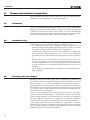
Studer Infinity Core (For Vista V and Vista X Systems) Operating Instructions (March 2015, 1st Edition) Prepared and edited by Studer Professional Audio GmbH Technical Documentation Riedthofstrasse 214 CH-8105 Regensdorf – Switzerland http://www.studer.ch Copyright by Studer Professional Audio GmbH Printed in Switzerland Order no. 5057249 Studer is a registered trade mark of Studer Professional Audio GmbH, Regensdorf Subject to change Safety Information For Your Own Safety and to Avoid Invalidation of the Warranty Please Read This Section Carefully • • • • • • • Read these instructions Keep these instructions Heed all warnings Follow all instructions Do not use this apparatus near water Clean only with a dry cloth Do not block any ventilation openings. Install in accordance with the manufacturer’s instructions • Do not install near any heat sources such as radiators, heat registers, stoves, or other apparatus (including amplifiers) that produce heat • Do not defeat the safety purpose of a polarised or grounding type plug. A polarised plug has two blades with one wider than the other. A grounding type plug has two blades and a third grounding prong. The wide blade or the third prong are provided for your safety. If the provided plug does not fit into your outlet, consult an electrician for replacement of the obsolete outlet • Protect the power cord from being walked on or pinched particularly at plugs, convenience receptacles and the point where they exit from the apparatus • Only use attachments/accessories specified by the manufacturer • Use only with the cart, stand, tripod, bracket or table specified by the manufacturer, or sold with the apparatus. When a cart is used, use caution when moving the cart/apparatus combination to avoid injury from tip-over • Refer all servicing to qualified service personnel. Servicing is required when the apparatus has been damaged in any way, such as the power supply cord or plug is damaged, liquid has been spilled or objects fallen into the apparatus, the apparatus has been exposed to rain or moisture, does not operate normally, or has been dropped Note: It is recommended that all maintenance and service on the product should be carried out by Studer or its authorised agents. Studer cannot accept any liability whatsoever for any loss or damage caused by service, maintenance or repair by unauthorised personnel WARNING: To reduce the risk of fire or electric shock, do not expose this apparatus to rain or moisture. Do not expose the apparatus to dripping or splashing and do not place objects filled with liquids, such as vases, on the apparatus • No naked flame sources, such as lighted candles, should be placed on the apparatus • Ventilation should not be impeded by covering the ventilation openings with items such as newspapers, table cloths, curtains etc WARNING: Do not use this apparatus in very dusty atmospheres, or in atmospheres containing flammable gases or chemicals • THIS APPARATUS MUST BE EARTHED. Under no circumstances should the safety earth be disconnected from the mains lead • The mains supply disconnect device is the mains plug. It must remain accessible so as to be readily operable when the apparatus is in use • If any part of the mains cord set is damaged, the complete cord set should be replaced. The following information is for reference only. The wires in the mains lead are coloured in accordance with the following code: I Safety Information • Protective Earth (Ground): Green/Yellow (US: Green or Green/ Yellow) • Neutral: Blue (US: White) • Live (Hot): Brown (US: Black) As the colours of the wires in the mains lead may not correspond with the coloured markings identifying the terminals in your plug, proceed as follows: • The wire which is coloured Green and Yellow must be connected to the terminal in the plug which is marked with the letter E or by the earth symbol • The wire which is coloured Blue must be connected to the terminal in the plug which is marked with the letter N • The wire which is coloured Brown must be connected to the terminal in the plug which is marked with the letter L Ensure that these colour codes are followed carefully in the event of the plug being changed • This unit is capable of operating over a range of mains voltages, as marked on the rear panel Lithium Battery ! ! Installed lithium batteries must be replaced by the same or an equivalent type. Danger of explosion if batteries are incorrectly replaced or when terminals are shorted. Installed lithium batteries must not be exposed to excessive heat such as direct sunshine, fire or the like. Note: This equipment has been tested and found to comply with the limits for a Class A digital device, pursuant to Part 15 of the FCC Rules. These limits are designed to provide reasonable protection against harmful interference when the equipment is operated in a commercial environment. This equipment generates, uses and can radiate radio frequency energy and, if not installed and used in accordance with the instruction manual, may cause harmful interference to radio communications. Operation of this equipment in a residential area is likely to cause harmful interference in which case the user will be required to correct the interference at his own expense. This Class A digital apparatus meets the requirements of the Canadian Interference-Causing Equipment Regulations. Cet appareil numérique de la Classe A respecte toutes les exigences du Règlement sur le matériel brouilleur du Canada. Working Safely With Sound Although your new console will not make any noise until you feed it signals, it has the capability to produce sounds that, when monitored through a monitor system or headphones, can damage hearing over time.The table below is taken from the Occupational Safety & Health Administration directive on occupational noise exposure (1926.52): Permissible Noise Exposure: ! II Duration per day [h] 8 6 4 3 2 1.5 1 0.5 <0.25 Sound level [dBA, slow response] 90 92 95 97 100 102 105 110 115 Safety Information A1 Conforming to this directive will minimise the risk of hearing damage caused by long listening periods. A simple rule to follow is: The longer you listen, the lower the average volume should be. Please take care when working with your audio system – if you are manipulating controls which you don’t understand (which we all do when we are learning), make sure your monitoring level is turned down. Remember that your ears are the most important tool of your trade. Look after them, and they will look after you. Most importantly: Don’t be afraid to experiment to find out how each parameter affects the sound; this will extend your creativity and help you to get the best results. Safety Symbol Guide For your own safety and to avoid invalidation of the warranty, all text marked with these symbols should be read carefully. CAUTION To reduce the risk of electric shock, do not remove covers. No user-serviceable parts inside. Refer servicing to qualified service personnel (i.e., persons having appropriate technical training and experience necessary to be aware of hazards to which they are exposed in performing a repair action, and of measures to minimize the danger of themselves). RISK OF ELECTRIC SHOCK DO NOT OPEN ATTENTION RISQUE DE CHOC ELECTRIQUE NE PAS OUVRIR ACHTUNG GEFAHR: ELEKTRISCHER SCHLAG NICHT ÖFFNEN The lightning flash with arrowhead symbol is intended to alert the user to the presence of un-insulated “dangerous voltage” within the product’s enclosure that may be of sufficient magnitude to constitute a risk of electric shock to persons. The exclamation point within an equilateral triangle is intended to alert the user to the presence of important operating and maintenance (servicing) instructions in the literature accompanying the appliance. ! Headphones safety warnings contain important information and useful tips on headphone outputs and monitoring levels. ! Assemblies or sub-assemblies of this product can contain opto-electronic CLASS 1 devices. As long as these devices comply with Class I of laser or LED prodLED PRODUCT ucts according to EN 60825-1:1994, they will not be expressly marked on the product. If a special design should be covered by a higher class of this CLASS 1 standard, the device concerned will be marked directly on the assembly or LASER PRODUCT sub-assembly in accordance with the above standard. A2 First Aid In Case of Electric Shock: Separate the person as quickly as possible from the electric power source: • By switching the equipment off, • By unplugging or disconnecting the mains cable, or • By pushing the person away from the power source, using dry insulating material (such as wood or plastic) • After having suffered an electric shock, always consult a doctor Warning! Do not touch the person or his clothing before the power is turned off, otherwise you stand the risk of suffering an electric shock as well! If the Person is Unconscious: • • • • • Lay the person down Turn him to one side Check the pulse Reanimate the person if respiration is poor Call for a doctor immediately. III Installation B General Installation Instructions Please consider besides these general instructions also any product-specific instructions in the “Installation” chapter of this manual. B1Unpacking Check the equipment for any transport damage. If the unit is mechanically damaged, if liquids have been spilled or if objects have fallen into the unit, it must not be connected to the AC power outlet, or it must be immediately disconnected by unplugging the power cable. Repair must only be performed by trained personnel in accordance with the applicable regulations. B2 Installation Site B3 Install the unit in a place where the following conditions are met: • The temperature and the relative humidity of the environment must be within the specified limits during operation of the unit. Relevant values are the ones at the air inlets of the unit (refer to Appendix 1) • Condensation must be avoided. If the unit is installed in a location with large variation of ambient temperature (e.g. in an OB-van), appropriate precautions must be taken before and after operation (refer to Appendix 1) • Unobstructed air flow is essential for proper operation. Air vents of the unit are a functional part of the design and must not be blocked in any way during operation (e.g. by objects placed upon them, placement of the unit on a soft surface, or installation of the unit within a rack or piece of furniture) • The unit must not be heated up by external sources of heat radiation (sunlight, spotlights) Earthing and Power Supply Earthing of units with mains supply (class I equipment) is performed via the protective earth (PE) conductor integrated in the mains cable. Units with battery operation (< 60 V, class III equipment) must be earthed separately. Earthing the unit is one of the measures for protection against electrical shock hazard (dangerous body currents). Hazardous voltage may not only be caused by a defective power supply insulation, but may also be introduced by the connected audio or control cables. If the unit is installed with one or several external connections, its earthing must be provided during operation as well as while the unit is not operated. If the earthing connection can be interrupted, for example, by unplugging the mains plug of an external power supply unit, an additional, permanent earthing connection must be installed using the provided earth terminal. Avoid ground loops (hum loops) by keeping the loop surface as small as possible (by consequently guiding the earth conductors in a narrow, parallel way), and reduce the noise current flowing through the loop by inserting an additional impedance (common-mode choke). IV Installation / EMC Class I Equipment (Mains Operation) Should the equipment be delivered without a matching mains cable, the latter has to be prepared by a trained person using the attached female plug (IEC 320 / C13 or IEC 320 / C19) with respect to the applicable regulations in your country. Before connecting the equipment to the AC power outlet, check that the local line voltage matches the equipment rating (voltage, frequency) within the admissible tolerance. The equipment fuses must be rated in accordance with the specifications on the equipment. Equipment supplied with a 3-pole appliance inlet (protection conforming to class I equipment) must be connected to a 3-pole AC power outlet in such a way that the equipment cabinet is connected to the protective earth. For information on mains cable strain relief, please refer to Appendix 2. Female Plugs (IEC320), Front-Side View: L N L PE PE IEC 320 / C13 IEC 320 / C19 European Standard (CENELEC) Brown Blue Green/Yellow N North American Standard (NAS) L (Live) N (Neutral) PE (Protective Earth) Black White Green (or Green/Yellow) Class III Equipment (Battery Operation up to 60 VDC) Equipment of this protection class must be earthed using the provided earth terminal if one or more external signals are connected to the unit (see explanation at the beginning of this paragraph). B4 Electromagnetic Compatibility (EMC) The unit conforms to the protection requirements relevant to electromagnetic phenomena that are listed in guidelines 89/336/EC and FCC, part 15. • The electromagnetic interference generated by the unit is limited in such a way that other equipment and systems can be operated normally • The unit is adequately protected against electromagnetic interference so that it can operate properly The unit has been tested and conforms to the EMC standards of the specified electromagnetic environment, as listed in the following declaration. The limits of these standards ensure protection of the environment and corresponding noise immunity of the equipment with appropriate probability. However, a professional installation and integration within the system are imperative prerequisites for operation without EMC problems. For this purpose, the following measures must be followed: • Install the equipment in accordance with the operating instructions. Use the supplied accessories • In the system and in the vicinity where the equipment is installed, use only components (systems, equipment) that also fulfill the EMC standards for the given environment V EMC / Maintenance / ESD C • Use a system grounding concept that satisfies the safety requirements (class I equipment must be connected with a protective ground conductor) and that also takes into consideration the EMC requirements. When deciding between radial, surface, or combined grounding, the advantages and disadvantages should be carefully evaluated in each case • Use shielded cables where shielding is specified. The connection of the shield to the corresponding connector terminal or housing should have a large surface and be corrosion-proof. Please note that a cable shield connected only single-ended can act as a transmitting or receiving antenna within the corresponding frequency range • Avoid ground loops or reduce their adverse effects by keeping the loop surface as small as possible, and reduce the noise current flowing through the loop by inserting an additional impedance (e.g. common-mode choke). • Reduce electrostatic discharge (ESD) of persons by installing an appropriate floor covering (e.g. a carpet with permanent electrostatic filaments) and by keeping the relative humidity above 30%. Further measures (e.g. conducting floor) are usually unnecessary and only effective if used together with corresponding personal equipment • When using equipment with touch-sensitive operator controls, please take care that the surrounding building structure allows for sufficient capacitive coupling of the operator. This coupling can be improved by an additional, conducting surface in the operator’s area, connected to the equipment housing (e.g. metal foil underneath the floor covering, carpet with conductive backing) Maintenance All air vents and openings for operating elements (faders, rotary knobs) must be checked on a regular basis, and cleaned in case of dust accumulation. For cleaning, a soft paint-brush or a vacuum cleaner is recommended. Cleaning the surfaces of the unit is performed with a soft, dry cloth or a soft brush. Persistent contamination can be treated with a cloth that is slightly humidified with a mild cleaning solution, such as dishwashing detergent. For cleaning display windows, commercially available computer/TV screen cleaners are suited. Use only a slightly damp (never wet) cloth. Never use any solvents for cleaning the exterior of the unit! Liquids must never be sprayed or poured on directly! For equipment-specific maintenance information please refer to the corresponding chapter in the operating and service manuals. D Electrostatic Discharge during Maintenance and Repair Caution: Observe the precautions for handling devices sensitive to electrostatic discharge! Many semiconductor components are sensitive to electrostatic discharge (ESD). The lifespan of assemblies containing such components can be drastically reduced by improper handling during maintenance and repair. Please observe the following rules when handling ESD sensitive components: • ESD sensitive components should only be stored and transported in the packing material specifically provided for this purpose VI ESD / Repair E Repair • When performing a repair by replacing complete assemblies, the removed assembly must be sent back to the supplier in the same packing material in which the replacement assembly was shipped. If this should not be the case, any claim for a possible refund will be null and void • Unpacked ESD sensitive components should only be handled in ESD protected areas (EPA, e.g. area for field service, repair or service bench) and only be touched by persons wearing a wristlet connected to the ground potential of the repair or service bench by a series resistor. The equipment to be repaired or serviced as well as all tools and electrically semi-conducting work, storage, and floor mats should also be connected to this ground potential • The terminals of ESD sensitive components must not come in uncontrolled contact with electrostatically chargeable or metallic surfaces (voltage puncture, discharge shock hazard) • To prevent the components from undefined transient stress and possible damage due to inadmissible voltages or compensation currents, electrical connections should only be established or separated when the equipment is switched off and after any capacitor charges have decayed By removing housing parts or shields, energized parts may be exposed. For this reason the following precautions must be observed: • Maintenance may only be performed by trained personnel in accordance with the applicable regulations • The equipment must be switched off and disconnected from the AC power outlet before any housing parts are removed • Even if the equipment is disconnected from the power outlet, parts with hazardous charges (e.g. capacitors, picture tubes) must not be touched until they have been properly discharged. Do not touch hot components (power semiconductors, heat sinks, etc.) before they have cooled off • If maintenance is performed on a unit that is opened while being switched on, no un-insulated circuit components and metallic semiconductor housings must be touched, neither with bare hands nor with un-insulated tools Certain components pose additional hazards: • Explosion hazard from lithium batteries, electrolytic capacitors and power semiconductors (Observe the component’s polarity. Do not short battery terminals. Replace batteries only by the same type) • Implosion hazard from evacuated display units • Radiation hazard from laser units (non-ionizing), picture tubes (ionizing). • Caustic effect of display units (LCD) and components containing liquid electrolyte Such components should only be handled by trained personnel who are properly protected (e.g. protection glasses, gloves) VII Repair / Disposal E1 SMD Components Studer has no commercially available SMD components in stock for service purposes. For repair, the corresponding devices have to be purchased locally. The specifications of special components can be found in the service manual. SMD components should only be replaced by skilled specialists using appropriate tools. No warranty claims will be accepted for circuit boards that have been damaged. Proper and improper SMD soldering joints are illustrated below. Copper Track SMD Component Soldering Iron Solder PCB Adhesive Dismounting Desoldering Iron Soldering Iron 1 2 3 Desolder Wick Desolder Wick Heat and Remove Mounting Cleaning Examples 1 2 Solder Ø 0.5...0.8 mm 3 Heating Time < 3 s per Side F Disposal Packing Materials The packing materials have been selected with environmental and disposal issues in mind. All packing material can be recycled. Recycling packing saves raw materials and reduces the volume of waste. If you need to dispose of the transport packing materials, please try to use recyclable means. Used Equipment VIII Used equipment contains valuable raw materials as well as materials that must be disposed of professionally. Please return your used equipment via an authorized specialist dealer or via the public waste disposal system, ensuring any material that can be recycled is. Please take care that your used equipment cannot be abused. To avoid abuse, delete sensitive data from any data storage media. After having disconnected your used equipment from the mains supply, make sure that the mains connector and the mains cable are made useless. Conformity G G1 Declarations of Conformity Class A Equipment - FCC Notice This equipment has been tested and found to comply with the limits for a Class A digital device, pursuant to Part 15 of the FCC Rules. These limits are designed to provide a reasonable protection against harmful interference when the equipment is operated in a commercial environment. This equipment generates, uses, and can radiate radio frequency energy and, if not installed and used in accordance with the instruction manual, may cause harmful interference to radio communications. Operation of this equipment in a residential area is likely to cause harmful interference, in which case the user will be required to correct the interference at his own expense. This Class A digital apparatus meets the requirements of the Canadian Interference-Causing Equipment Regulations. G2 Cet appareil numérique de la Classe A respecte toutes les exigences du Règlement sur le matériel brouilleur du Canada. Caution: Any changes or modifications not expressly approved by the manufacturer could void the user’s authority to operate the equipment. Also refer to relevant information in this manual. CE Declaration of Conformity We, Studer Professional Audio GmbH, CH-8105 Regensdorf, declare under our sole responsibility that the product Studer Infinity Core (starting with serial no. 4101), to which this declaration relates, according to following regulations of EU directives and amendments is in conformity with the following standards or normative documents: Conformity to be declared here IX Appendix Appendix 1: Air Temperature and Humidity General Normal operation of the unit or system is warranted under the ambient conditions defined by EN 60721-3-3, set IE32, value 3K3. This standard consists of an extensive catalogue of parameters, the most important of which are: ambient temperature +5...+40 °C, relative humidity 5...85% (i.e., no formation of condensation or ice); absolute humidity 1...25 g/ m³; rate of temperature change < 0.5 °C/min. These parameters are dealt with in the following paragraphs. Under these conditions the unit or system starts and works without any problem. Beyond these specifications, possible problems are described below. Ambient Temperature Units and systems by Studer are generally designed for an ambient temperature range (i.e. temperature of the incoming air) of +5 °C to +40 °C. When rack mounting the units, the intended air flow and herewith adequate cooling must be provided. The following facts must be considered: • The admissible ambient temperature range for operation of the semiconductor components is 0 °C to +70 °C (commercial temperature range for operation) • The air flow through the installation must provide that the outgoing air is always cooler than 70 °C • Average heat increase of the cooling air shall be about 20 K, allowing for an additional maximum 10 K increase at the hot components • In order to dissipate 1 kW with this admissible average heat increase, an air flow of 2.65 m³/min is required Example: A rack dissipating P = 800 W requires an air flow of 0.8 * 2.65 m³/min which corresponds to 2.12 m³/min. • If the cooling function of the installation must be monitored (e.g. for fan failure or illumination with spot lamps), the outgoing air temperature must be measured directly above the modules at several places within the rack. The trigger temperature of the sensors should be 65 °C to 70 °C Frost and Dew The unsealed system parts (connector areas and semiconductor pins) allow for a minute formation of ice or frost. However, formation of dew visible to the naked eye will already lead to malfunctions. In practice, reliable operation can be expected in a temperature range above –15 °C, if the following general rule is considered for putting the cold system into operation: If the air within the system is cooled down, the relative humidity rises. If it reaches 100%, condensation will arise, usually in the boundary layer between the air and a cooler surface, together with formation of ice or dew at sensitive areas of the system (contacts, IC pins, etc.). Once internal condensation occurs, trouble-free operation cannot be guaranteed, independent of temperature. X Before putting into operation, the system must be checked for internal formation of condensation or ice. Only with a minute formation of ice, direct Appendix Example 1: Example 2: evaporation (sublimation) may be expected; otherwise the system must be heated and dried while switched off. A system without visible internal formation of ice or condensation should be heated up with its own heat dissipation, as homogeneously (and subsequently as slow) as possible; the ambient temperature should then always be lower than the one of the outgoing air. If it is absolutely necessary to operate the cold system immediately within warm ambient air, this air must be dehydrated. In such a case, the absolute humidity must be so low that the relative humidity, related to the coldest system surface, always remains below 100%. Ensure that the enclosed air is as dry as possible when powering off (i.e. before switching off in winter, aerate the room with cold, dry air, and remove humid objects such as clothes from the room). These relationships are visible from the following climatogram. For a controlled procedure, thermometer and hygrometer as well as a thermometer within the system will be required. An OB-van having an internal temperature of +20 °C and a relative humidity of 40% is switched off in the evening. If the temperature falls below +5 °C, the relative humidity will rise to 100% (7 g/m³); dew or ice will be forming. An OB-van is heated up in the morning with air of +20 °C and a relative humidity of 40%. On all parts being cooler than +5 °C, dew or ice will be forming. XI Appendix Appendix 2: Mains Connector Strain Relief XII For anchoring connectors without a mechanical lock (e.g. IEC mains connectors), we recommend the following arrangement: Procedure: The cable clamp shipped with your unit is auto-adhesive. For mounting please follow the rules below: • The surface to be adhered to must be clean, dry, and free from grease, oil, or other contaminants. Recommended application temperature range is +20 °C to +40 °C • Remove the plastic protective backing from the rear side of the clamp and apply it firmly to the surface at the desired position. Allow as much time as possible for curing. The bond continues to develop for as long as 24 hours • For improved stability, the clamp should be fixed with a screw. For this purpose, a self-tapping screw and an M4 bolt and nut are included • Place the cable into the clamp as shown in the illustration above and firmly press down the internal top cover until the cable is fixed Appendix Appendix 3: Software License Use of the software is subject to the Studer Professional Audio Software License Agreement set forth below. Using the software indicates your acceptance of this license agreement. If you do not accept these license terms, you are not authorized to use this software. Under the condition and within the scope of the following Terms and Conditions, Studer Professional Audio GmbH (hereinafter ‘Studer’) grants the right to use programs developed by Studer as well as those of third parties which have been installed by Studer on or within its products. References to the license programs shall be references to the newest release of a license program installed at the Customer’s site. Programs Covered by the Agreement License Programs of Studer The following Terms and Conditions grant the right to use all programs of Studer that are part of the System and/or its options at the time of its delivery to the Customer, as well as the installation software on the original data disk and the accompanying documentation (‘License Material’). In this Agreement the word ‘Programs’ shall have the meaning of programs and data written in machine code. Using the software indicates your acceptance of this license agreement. If you do not accept these license terms, you are not authorized to use this software. Programs of Third Parties Programs of third parties are all programs which constitute part of the System and/or its options at the time of delivery to the Customer but have not been developed by Studer. The following conditions are applicable to programs of third parties: • The right to use third parties’ programs is governed by the License Agreement attached hereto (if applicable), which is an integral part of this Agreement. The Customer shall sign any and all License Agreements for all further programs of third parties installed on the system. The Customer shall be deemed to have received all License Agreements upon delivery of the system and/or its options • Studer shall accept no responsibility or liability for, and gives no warranties (express or implied) as to the programs of third parties. The Customer waives any and all claims versus Studer for any consequential damages, which might occur due to defects of these programs Right of Use Principle Studer grants the Customer the non-exclusive right to use the License Material in one copy on the system and/or its options as laid down by the Sales Agreement concluded between the parties and all Terms and Conditions which shall be deemed to form and be read and construed as part of the Sales Agreement. This right is assignable according to the ‘Assignability’ paragraph hereinafter. Customized Configurations The Customer is not entitled to alter or develop further the License Material except within the expressly permitted configuration possibilities given by the software installed on the system or elsewhere. All altered programs, including but not limited to the products altered within the permitted configuration possibilities, are covered by this License Agreement. XIII Appendix Reverse Engineering Reverse engineering is only permitted with the express consent of Studer. The consent of Studer can be obtained but is not limited to the case in which the interface software can not be provided by Studer. In any case Studer has to be informed immediately upon complete or partial reverse engineering. Copying the License Material The Customer is entitled to make one copy of all or parts of the License Material as is necessary for the use according to this Agreement, namely for backup purposes. The Customer shall apply the copyright of Studer found on the License Material onto all copies made by him. Records shall be kept by the Customer regarding the amount of copies made and their place of keeping. The responsibility for the original program and all copies made lies with the Customer. Studer is entitled to check these records on first request. Copies not needed anymore have to be destroyed immediately. Disclosure of License Material The License Material is a business secret of Studer. The Customer shall not hand out or in any way give access to parts of or the complete License Material to third parties nor to publish any part of the License Material without prior written consent of Studer. The Customer shall protect the License Material and any copies made according to the paragraph above by appropriate defense measures against unauthorized access. This obligation of non-disclosure is a perpetual obligation. Third parties are entitled to have access to the License Material if they use the License Material at the Customer’s site in compliance with this Agreement. Under no circumstance are third parties entitled to have access to the installation software on the original data media. The Customer shall safeguard the original data media accordingly. Assignability The rights granted to the Customer according to this License Agreement shall only be assignable to a third party together with the transfer of the system and/or its options and after the prior written consent of Studer. Rights to License Material With the exception of the right of use granted by this License Agreement all proprietary rights to the License Material, especially the ownership and the intellectual property rights (such as but not limited to patents and copyright) remain with Studer even if alterations, customized changes or amendments have been made to the License Material. Studer’s proprietary rights are acknowledged by the Customer. The Customer shall undertake no infringements and make no claims of any patent, registered design, copyright, trade mark or trade name, or other intellectual property right. Warranty, Disclaimer, and Liability XIV For all issues not covered herewithin, refer to the ‘General Terms and Conditions of Sales and Delivery’ being part of the sales contract. Infinity Core CONTENTS 1General...............................................................................................................................................................3 1.1 Utilization for the Purpose Intended....................................................................................................................3 1.2 First Steps............................................................................................................................................................3 1.2.1 Unpacking and Inspection...................................................................................................................................... 3 1.2.2Installation.............................................................................................................................................................. 3 1.2.3 Adjustments, Repair, Cleaning............................................................................................................................... 5 1.2.4Servicing................................................................................................................................................................ 5 2Introduction........................................................................................................................................................6 2.1 Key Features........................................................................................................................................................7 2.2Hardware.............................................................................................................................................................8 2.3Connections.........................................................................................................................................................9 2.4 System Setup.....................................................................................................................................................10 2.5 Clocking concept of the Infinity core................................................................................................................18 2.6Redundancy.......................................................................................................................................................18 2.7 Service Mode.....................................................................................................................................................19 2.8 Session Configuration Tool...............................................................................................................................20 2.9 Vista Surveyor Information...............................................................................................................................22 3Modules.............................................................................................................................................................25 3.1 Core Link Card..................................................................................................................................................25 3.2 Primary Power Supply...................................................................................................................................... 26 3.3 D23m and D21m I/O Subsystem.......................................................................................................................26 4Dimensions.......................................................................................................................................................27 Disclaimer Document generated: 18.03.15 The information in this document has been carefully checked and is believed to be accurate at the time of publication. However, no responsibility is taken by us for inaccuracies, errors, or omissions, nor is any liability assumed for any loss or damage resulting either directly or indirectly from use of the information contained within it. Infinity Core 1 Infinity Core 2 Infinity Core Document generated: 18.03.15 Infinity Core 1 General 1.1 Utilization for the Purpose Intended 1.2 The Studer Infinity Core system is intended for professional use. It is presumed that the unit is operated only by trained personnel. Servicing is reserved to skilled technicians. The electrical connections may be connected only to the voltages and signals designated in this manual. First Steps 1.2.1 Unpacking and Inspection Your new system is shipped in a special packing which protects the units against mechanical shock during transit. Care should be exercised when unpacking so that the surfaces do not get marred. Check the condition of the equipment for signs of shipping damage. If there should be any complaints you should immediately notify the forwarding agent and your nearest Studer distributor. Please retain the original packing material because it offers the best protection in case your equipment ever needs to be transported. 1.2.2 Installation Primary Voltage The power supply units are auto-ranging; they can be used for mains voltages in a range of 90 to 264 VAC, 47 to 63 Hz. Power Connection The attached female IEC 320/C13 mains cable sockets have to be connected to appropriate mains cables by a trained technician, respecting your local regulations. Refer to the ‘Installation, Operation, and Waste Disposal’ chapter at the beginning of this document. Earthing This equipment must be earthed, due to the mains input filter network being connected to the mains earth. Some consideration must be given to the earthing arrangement of the system, at the center of which is the frame. The frame is earthed to the mains earth via the power supply. Thermal Considerations The unit must not be used in conditions of excessive heat or cold, near any source of moisture, in excessively humid environments, or in positions where it is likely to be subjected to vibration or dust. The ambient temperature range for normal operation of the unit is +5...+40° C. Principal Rule The cooler the better – a temperature increase of only 10° C (18° F) reduces component lifetime by 50%! Document generated: 18.03.15 Infinity Core 3 Infinity Core Heat dissipation The following table lists the required heat dissipation which is depending on the type of the Infinity Core ( Core 200, Core 400, Core 800 ) : Core 200 Required Heat Dissipation 140 W Core 400 250 W Core 800 350 W Infinity Core Type If the unit is mounted in a climatised rack, please note that air intake must be at the front and air outlet at the rear of the rack. If two Infinity Cores are mounted on top of each other, there is no space required between the two units. If two Infinity Cores are mounted on top of each other, it is recommended to mount an air deflector panel on the very top of the two units. This air deflector panel then directs the hot air to the rear of the rack. Single Infinity Core No Air Deflector Unit needed Dual Infinity Core 1 Air Deflector Unit on top Air Air Air Infinity Core Rear Air Infinity Core Air Front 4 Infinity Core Infinity Core Rear Front Document generated: 18.03.15 Infinity Core 1.2.3 Adjustments, Repair, Cleaning Danger! All internal adjustments as well as repair work on this product must be performed by expert technicians! Replacing the Supply Unit The primary fuse is located within the power supply module and cannot be changed. In case of failure, the complete power supply unit must be replaced. Please ask your nearest Studer representative. Cleaning Do not use any liquids to clean the exterior of the unit. A soft, dry cloth or brush will usually do. 1.2.4 Servicing Slide out frame for servicing For easy servicing, the eight main screws on the front need to be unscrewed (this is even possible without any tool), to allow the sliding out of the chassis towards the front of the rack. Document generated: 18.03.15 Infinity Core 5 Infinity Core 2 Introduction The Infinity Core system makes use of standard x86-CPUs for audio signal processing. This has the great benefit that every new generation of CPU increases the channel-count that can be processed by this system. While audio processing is calculated by the CPUs, the actual mixing (summation) is done on a fast FPGA hardware module. A Linux OS provides high availability as well as shortest audio latency which both are important requirements in professional audio. The use of the current Intel® Xeon® processor series (February 2015) allows the following channel-counts (mono equivalent channels) for the three different Infinity Core systems : Infinity Core Type MEQ channels Core 200 200 Core 400 400 Core 800 800 Note : One MEQ channel consists of channel input processing (gain, mono sum etc), four band parametric EQ, notch, and HP/LP filters, four section dynamics, insert, channel delay plus fader and pan/balance controls. Summation is provided by the FPGA hardware where up to 768 mixing busses can be processed at the same time. The Infinity Core system is housed in a self-containing unit and occupies just 5U of rack space. The complete electronics are mounted on a sliding frame, allowing simple access for service and repair. 6 Infinity Core The Session Configuration Tool software, available as a standard, allows clients to take the factory-defined settings, and make their own adjustments on Document generated: 18.03.15 Infinity Core a job-by-job basis, including changing the number of input channels, buses, and outputs. The Infinity Core system maintains full redundancy, with redundant fan system, redundant power supplies, redundant link between core and console, and even complete core redundancy. In case of a hardware failure, the redundant core will take over the processing immediately without any audible disturbance. 2.1 Key Features DSP • Configurable DSP Core via provided configuration tool • Supported Channel Count: Core 200: 200 MEQ+ Core 400: 400 MEQ+ Core 800: 800 MEQ+ • Supported Bus Count Up to 768 summation busses • Tie line patching does not consume DSP (Direct input to output patching) • Sampling Frequencies: 44.1 kHz, 48 kHz, 88.2 kHz, 96 kHz I/O • Ethernet tunneling via A-Link for connected D23m devices • I/O Configuration 11x A-Link, 768 Channels each 1x Ethernet connection for Ethernet tunneling via A-Link Communication • Communication via UDP Broadcast or UDP Multicast (configurable) • Static IP Addresses (configurable) • Static Node identifiers (configurable) Redundancy Service and Maintenance • USB Ports • Web Interface for configuration and software updates • Bootable USB stick for complete factory re-imaging (requires USB Keyboard and Monitor connected) Document generated: 18.03.15 • 2 Ethernet Network Ports on Main Board • System Level redundancy - Multiple cores in parallel • Redundant Network connections • VGA Port for external monitor Infinity Core 7 Infinity Core 2.2 Hardware The mainboard within the Infinity Core is a high-end, standard form factor industrial server mainboard with an Intel chip-set. It is fitted with up to two Intel® Xeon® CPUs and one STUDER PCIe I/O card (Core Link Card). Dual power supplies are fitted, with two separate AC inlets. Fan Dust Filter Power On/Off Switch Status LEDs AC Inlet AC Inlet Dust Filter The ventilation system has a large air inlet with a foam dust filter in the front of the unit. Please note that this filter needs to be cleaned on a regular basis in order to provide sufficient air flow. Power On/Off Switch The Power On/Off Switch is also located on the front panel of the unit. To turn the system on, simply switch on the AC power by the switches above the AC inlets. The blue led ring around the Power On/Off button will illuminate to indicate that power is available and the fans will start. If the AC is already connected then press the large Power On/Off button to start up the core. To power down the core simply press the illuminated blue button, the system will shut down (this may take a few seconds). Status LEDs The Status LEDs display the following information about the status of the Infinity Core : Status LEDs Off Blink Green Green Blink Red Red I/O Link Power off Power up Core Link Card OK Core Link Fan fail Core Link Card error System Power off Waiting for configuration DSP Processing OK Sync Loss DSP or Hardware error Active Power off or Slave DSP Processing Offline Master DSP Processing Master DSP Processing - - 8 Infinity Core Document generated: 18.03.15 Infinity Core 2.3 Connections Ethernet The two Ethernet control connections are normally directly linked to the two Ethernet switches of the desk. A-Link There are 12 A-Link ports to bring audio in-, as well as out of the Infinity core. A-Link is a “super-fast” optical interface comprising a duplex fibre pair of connections capable of carrying up to 1536 channels of 24 bit audio. 11 interfaces are configured to provide 768 mono channels of inputs and 768 mono channels of outputs, port 12 is configured as an Ethernet port to allow embedding of Ethernet data via A-Link to the connected D23m frames. SFP The A-Link interface uses SFP modules as connectors. SFP stands for Small Form-factor Pluggable. These are small modules that plug into the carrier on the card and are available in various optical frequencies and powers according to transmission distance, fibre type and data load. They use “LC” fibre connectors. Fitted as standard are 4.25Gb/s 850nm Multimode SFPs, this will allow distances of up to 150m with 50μm/125μm fibre between units. For longer distances, Single mode (9μm) types should be used. Multi-mode SFP Part No. 5042823 Single-mode SFP Part No. 5042824 Ethernet connectors USB connectors USB connectors USB VGA Document generated: 18.03.15 11x A-Link connectors Ethernet tunneling for D23m devices via A-Link port 12 VGA screen connector USB ports can be used to connect USB memory sticks that contain SW images to upgrade the SW of the core. Then, also a USB keyboard can be connected to a USB port. The VGA port is also used for servicing only - a VGA screen can be connected Infinity Core 9 Infinity Core 2.4 System Setup General terms Node Id Each element (desk, core, D23m I/O frames) in the mixing console system is connected via Ethernet. The so called “Node Id” is used to identify each element uniquely so the software can communicate correctly. Thus each Node Id must be unique. Cloud Id It is often the case that several consoles will be connected together via Ethernet for resource sharing (such as Studer’s Relink). It is therefore necessary that each element must also have a second Id to allow each element to know which mixing system it is a part of; each Vista desk must know which Infinity Core (or Cores) is processing its audio. This second Id is known as the “Cloud Id” and must be set uniquely for each system. There are two different parts of the network which have the same Id : • Mixercloud • IOCloud The network part on which desk and I/O frames communicate. Eventhough the Cloud Id’s of the Mixercloud and the IOCloud are the same on one mixing system, the communication is kept separate between deks-core and desk-IO by using different Portnumbers and different UDP Multicast groups. This is what differntiates the Mixercloud from the IOCloud. Numbering Rules The Node Id is normally used as the last byte of the elements IP-address. The network part on which desk and cores communicate. Network configuration 10 Infinity Core With a new ordered Vista Mixing System these settings are already configured correctly. The diagram on the next page shows a complete overview of the network configuration of a multi Vista system. Document generated: 18.03.15 Config for IO Cloud Ext. Network Config for Mixer Cloud Node Id : 24 LAN : 192.168.1.24 Node Id : 23 LAN : 192.168.1.23 LAN : 192.168.1.25 Node Id : 25 Vista Redundant Meter Main Meter Redundant Vista Redundant Meter Main Port : 3000 UDP MulticastGroup : 239.255.42.1 Infinity Core Red. Node ID : 43 LAN1 : 192.168.1.43 LAN2 : 192.168.2.43 Infinity Core Main Node ID : 42 LAN1 : 192.168.1.42 LAN2 : 192.168.2.42 Infinity Core Node ID : 42 LAN1 : 192.168.1.42 LAN2 : 192.168.2.42 Cloud Id : 1 Port : 3000 UDP MulticastGroup : 239.255.42.1 Node Id: 10 Node Id: 20 Node Id: 11 Node Id: 21 LAN2:192.168.1.10 LAN2:192.168.1.20 LAN2:192.168.1.11 LAN2:192.168.1.21 LAN2:192.168.2.10 LAN2:192.168.2.20 LAN2:192.168.2.11 LAN2:192.168.2.21 LAN1:192.168.5.30 LAN1:192.168.5.30 LAN1:192.168.5.30 LAN1:192.168.5.30 LAN2:192.168.1.10 LAN2:192.168.1.20 LAN2:192.168.1.11 LAN2:192.168.1.21 LAN2:192.168.2.10 LAN2:192.168.2.20 LAN2:192.168.2.11 LAN2:192.168.2.21 Mixer Cloud Cloud Id : 1 Meter Redundant Node Id: 10 Node Id: 20 Node Id: 11 Node Id: 21 VistaMain Mixer Cloud Node Id: 10 Node Id: 20 Node Id: 11 Node Id: 21 LAN2:192.168.1.10 LAN2:192.168.1.20 LAN2:192.168.1.11 LAN2:192.168.1.21 LAN2:192.168.2.10 LAN2:192.168.2.20 LAN2:192.168.2.11 LAN2:192.168.2.21 LAN1:192.168.5.30 LAN1:192.168.5.30 LAN1:192.168.5.30 LAN1:192.168.5.30 LAN2:192.168.1.10 LAN2:192.168.1.20 LAN2:192.168.1.11 LAN2:192.168.1.21 LAN2:192.168.2.10 LAN2:192.168.2.20 LAN2:192.168.2.11 LAN2:192.168.2.21 Node Id: 10 Node Id: 20 Node Id: 11 Node Id: 21 VistaMain Vista Desk with 4 Control Systems Vista Desk with 4 Control Systems Cloud Id : 1 LAN : 192.168.1.26 Node Id : 26 Port : 3001 UDP MulticastGroup : 239.255.23.1 Relink HiQnet Network LAN : 192.168.1.24 LAN : 192.168.1.23 IO Cloud Node Id : 24 Node Id : 23 D23m Frame 1 D23m Frame 2 D23m Frame 3 D23m Frame 4 Port : 3001 UDP MulticastGroup : 239.255.23.1 Cloud Id : 1 IO Cloud D23m Frame 2 D23m Frame 1 System B Config for IO Cloud Ext. Network Document generated: 18.03.15 Config for Mixer Cloud System A Infinity Core Multi system network configuration overview Infinity Core 11 Infinity Core Setting up the Desk All system relevant settings of the Vista desk are configured in the D950System.ini file. With a new ordered Vista Mixing System these settings are already configured correctly. This section is only to explain the single lines in the file that are important for the correct configuration : [d950systeminfo] IsBridgeActive=Yes ç this must be set to Yes IsScoreUsed=No IsSpiderCoreUsed=No IsPCCoreUsed=Yes ç this must be set to Yes IsD19Active=No IsD21Active=No IsD23Active=Yes ç this must be set to Yes [Mixercloud] CloudId = 1 ç the Cloud Id defines the whole mixing system NodeId = 10 ç here the Node Id of the mixer must be set - different from all other nodes NodeName = “Vista X Desk” ç the name of the desk can be entered here ReceivePort = 3000 ç the default port for the mixercloud is always 3000 SendPort = 3000 ç the default port for the mixercloud is always 3000 UseMulticast = Yes ç this must be set to Yes MulticastGroup = 239.255.42.1 ç this is the default address for the Mixercloud Interfaces = “LAN 2” ç Name of network interfaces to be used for communication AnnounceActive = Yes ç the default setting is Yes AnnouncePeriodMs = 500 ç the default setting is 500 NetworkExpirationTimeMs = 2000 ç the default setting is 2000 LiveUpdateIntervalMs = 20 ç the default setting is 20 LiveUpdateSize = 5000 ç the default setting is 5000 SyncUpdateIntervalMs = 5000 ç the default setting is 5000 SyncUpdateSize = 5000 ç the default setting is 5000 [IOCloud] 12 Infinity Core CloudId = 1 ç defines the whole mixing system and is the same Id as the mixer cloud NodeId = 10 ç the Node Id of the mixer as set above in mixer cloud NodeName = “Vista X Desk” ç the name of the desk as above in mixer cloud ReceivePort = 3001 ç the default port for the IOCloud is always 3001 SendPort = 3001 ç the default port for the IOCloud is always 3001 UseMulticast = Yes ç this must be set to Yes MulticastGroup = 239.255.23.1 ç this is the default address for the IOCloud Interfaces = “LAN 2” ç Name of network interfaces to be used for communication Document generated: 18.03.15 Infinity Core In the section below, the needed A-Link ports must be enabled, by removing the semicolon in front of the definition of the max. 12 ports. System1= “ALK1” PortId=1 NodeId=23 ç this A-Link port is enabled ;System2= “ALK2” PortId=2 NodeId=24 ;System3= “ALK3” PortId=3 NodeId=25 ;System4= “ALK4” PortId=4 NodeId=26 ;System5= “ALK5” PortId=5 NodeId=27 ;System6= “ALK6” PortId=6 NodeId=28 ;System7= “ALK7” PortId=7 NodeId=29 ;System8= “ALK8” PortId=8 NodeId=30 ;System9= “ALK9” PortId=9 NodeId=31 ;System10= “ALK10” PortId=10 NodeId=32 ;System11= “ALK11” PortId=11 NodeId=33 ;System12= “ALK12” PortId=12 NodeId=34 The PortId is the A-LINK port index of the Inifinity Core to which the system is connected. The D23 system name (set in quotation marks) can be changed by the user. The NodeId is the unique Id used to address the corresponding D23 frame. Document generated: 18.03.15 Infinity Core 13 Infinity Core Setting up the Infinity Core Setting up a Infinity Core is done by using the browser based “Infinity Panel” - which normally is started from the Vista desk. Any Web browser can be started and the address of the core can be entered : 192.168.1.42:4000 (e.g. as this is the default address). Then, the Infinity Panel appears - if the desk is connected to the core - and the following five menu items can be accessed : Settings, Network, Software, Control and Log Settings On this page, the below described parameters are shown. All of these parameters can also be edited on this page : Node Name Cloud Id Node Id Communication Port Use Multicast Multicast Group Address Log level The name of this Infinity Core - e.g. Main Core or Redundant Core. The Cloud Id of the Mixer Cloud. The Node Id of this Infinity Core. As a default, the communication Port for the communication with Cores is Port 3000. This enables to use IP multicast group communication, making use of the UDP protocol. Here the IP multicast group address is defined. As a default, the Multicast Group Address for the communication with Cores is 239.255.42.1 . Here the level of details about the logged information is set. The dropdown menu allows the shown choice. (Infomation being the default setting). 14 Infinity Core Document generated: 18.03.15 Infinity Core Network Primary and secondary LAN network address can be viewn and configured on this page. Software This is the portal for software updates and information about the currently installed SW. A software version that has been uploaded onto the Core but is not currently installed, can also be deleted here by clicking the trashbin icon. When clicking on any of the shown software versions, a detailed information screen is displayed : Document generated: 18.03.15 Infinity Core 15 Infinity Core Control On this page, the Infinity Core software service can be restarted, or a hardware reboot of the Infinity Core can be executed. Log Here, the log files of the system can be shown or deleted. The level of details of the log files is depending on the parameter Log Level which can be set on the Settings page. Setting up the D23m frames Setting up a D23m frame is done by using the same browser based “Infinity Panel” as it is used for setting up a core. The Infinity Panel normally is started from the Vista desk. Any Web browser can be started and the address of the D23m frame can be entered : 192.168.1.23:4000 (e.g. as this is the default address). Then, the Infinity Panel appears - if the D23m frame is connected to the desk - and the same five menu items as when setting up a core can be accessed : 16 Infinity Core Document generated: 18.03.15 Infinity Core Node Name Cloud Id Node Id Communication Port Use Multicast Multicast Group Address Log level The name of this D23m frame. The Cloud Id of the IO Cloud. The Node Id of this D23m frame. As a default, the communication Port for the communication with IO frames is Port 3001. This enables to use IP multicast group communication, making use of the UDP protocol. Here the IP multicast group address is defined. As a default, the Multicast Group Address for the communication with IO frames is 239.255.23.1 . Here the level of details about the logged information is set. Going to the Settings page and clicking on the Edit button, there is also the possibility to reset all parameters to the defualt values. This is done by clicking on the red Reset to factory defaults button. Document generated: 18.03.15 Infinity Core 17 Infinity Core 2.5 Clocking concept of the Infinity core The Sync source of the Infinity core is always provided by a D23m frame. The Sync signal of the D23m system is etiher internally generated by one of the D23m frames, or an external sync signal is connected to one of the D23m frames. The sync signal is then transmitted to the core via A-Link. All other frames will be synced from the core via their audio interface (MADI or A-Link). The D23m system is able to connect to external sync sources to be synchronised. Following sync sources can be used: • Video • Word Clock • AES/EBU • A-Link (main or redundant) For Video 50 Hz, 59.94 Hz, and 60 Hz are supported. For all other sync sources 48 kHz, 96 kHz, 44.1 kHz and 88.2 kHz are supported. An automatic process is employed to ‘look’ for the best possible sync source. This process has the following rules : 1. External Clocks have higher priorities then internal clocks. 2. The priorities of the external sync signals are in this order : 1. Video reference, 2. Word clock, 3. AES/EBU 4. A-Link 3. The lowest A-Link portnumber (on the core) has the highest priority. 4. Once a switchover to a different sync source has occured, the system will automatically switch back to the original source, as soon as this sync signal is restored. If the D23m system consists of multiple frames and a redundant Infinity core system, the above process provides an audio clock redundancy. If the D23m frame which is the sync source, fails, the system will switch over to the next possible D23m frame that can be the sync master. 2.6 Redundancy The redundancy concept of the Infinity Core closely interacts with the redundancy of the D23m I/O system : The D23m host card (A-Link HD card) offers two A-Link ports, main and redundant with automatic switching - the D23m frame switches automatically to the redundant connection, in case the main connection fails. A-Link Quality of Service Every A-Link carries its Qualtiy of Service indication, which is depending on the state of the source that generates the A-Link signal. Looking at this QoS, the D23m system can decide to switch from the main A-Link to the redundant A-Link signal. QoS is taking into account the following criterias of the source that generates the A-Link signal : 18 Infinity Core Document generated: 18.03.15 Infinity Core • Is the core currently controlled (e.g. by a desk) ? Or has it no control ? • Are all SFP equipped A-Link ports active ? • Are dropouts occuring in the audio processing ? If at least one of these criterias is not met, the QoS of the A-Link signal gets reduced. Each D23m frame then switches to the A-Link port (main or redundant) with the better QoS value. With the Infinity Core, the customer can decide the level of redundancy. If A-Link cable redundancy is desired, two Infinity Cores have to be deployed. Then, of course also core redundancy is provided : should an audio dropout occur within the main core, the QoS of the A-Link signal is reduced and therefore the D23m frame switches to the redundant port where the redundant core is connected. In this case, also the active core would be switched from main to the redundant. Also in case of a hardware failure of the core, the redundant core will take over the processing immediately without any audible disturbance. 0...64 Ch Optical MADI .. D21m Remote I/O Frame 12 (Redundant) 0...64 Ch Optical MADI (redunant) 0...64 Ch Optical MADI D21m Remote I/O Frame 2 .. 0...64 Ch Optical MADI D21m Remote I/O Frame 1 0...64 Ch Optical MADI 0...64 Ch Optical MADI (redundant) D23m Frame with MADI I/O cards to connect to the Remote Frames Main Infinity Core 768 Ch Out Redundant Link 768 Ch In 768 Ch Out Main Link 768 Ch In D23m Frame Studer A-Link (optical fibre) Redundant Infinity Core Other Infinity Core system redundancy features are : redundant fan system, redundant power supplies, redundant control link between core and console. 2.7 Service Mode Document generated: 18.03.15 If a complete re-imaging or factory reset of the core is required, this can be done using a bootable USB stick and connect a monitor to the VGA port and a keyboard to the USB port. The USB stick contains software to re-image the core and some further tools for diagnostic purposes like memory checkers. Software updates and general support is managed from the Vista desk using the web interface described in chapter 2.4 Infinity Core 19 Infinity Core 2.8 Session Configuration Tool The Infinity Core uses almost the same concept of user configurable channel/ bus structures (Session Configurations) as the SCoreLive. In this chapter, the most obvious and most important differences to the Session Configuration Tool of the SCoreLive are explained. Differences to the Session Configuration Tool of the SCoreLive The Session Configuration Tool of the Infininty Core is not generating DSP program code - as needed for the SCoreLive - but it is generating a number of “simple” .xml files. Out of this fact, two major advantages evolve : 1. No licence is required for the compiling process 2. To generate a Session Configuration takes only very little time The resulting files of a compiled Session Configuration (“Generate All”) are three new files : • the XML Configuration : Configname.xml • the Mixer Cloud paths : Configname-MixercloudPaths.txt • the VMC Mappinginformation : Configname-VmcMappinginformation.xml Setup The Session Configuration Tool for the Infinity Core actually is the very same Session Configuration Tool as used for the SCoreLive (starting from SW 5.2.00). Whether it is used for the SCoreLive or for the Infinity Core is decided by the CoreConfigTool.ini file. There are two templates of the .ini files in the folder C:\CoreCfgTool : • CoreConfigTool.sCore • CoreConfigTool.ini CoreConfigTool.sCore è This file must be renamed to .ini when used with SCoreLive systems. CoreConfigTool.ini è This file is ready to be used with the Infinity Core systems. To doublecheck whether the correct version of the file is active, the file can be opened with a text editor and the entry ‘CoreType= ’ can be verified. When the Session Configuration Tool is set-up for the Infinity Core, it can be started with C:\CoreCfgTool\CoreCfgTool.exe.or with the shortcut on the desktop refering to this file. Then name of the Session Configuration Tool then is “ICoreCfgTool” which is shown on he very top of the program window - and the GUI of the tool looks as shown below. 20 Infinity Core Document generated: 18.03.15 Infinity Core Core Version As a big change to the SCoreLive-version of the Session Configuration Tool, here, the Infinity Core Version has to be chosen. This is an important setting. The Core Version must match the actual Core HW, as the load balancing of the Session Configuration Tool is set to this specific core size. This means that when this setting is not matching the actua HW core, the VMC configuration might not run at all. By going to the Tree- or Shared-view and by right-clicking on the parameter Core Version, the appropriate version can be chosen. N-X channels There is a new N-X channel/bus structure for the Infinity Core. The N-X bus now requires a master channel, as other busses do (e.g. Aux or Mst). This N-X master channel can be chosen amongst all other channel types. It is available in mono and stereo. So each N-X bus needs a N-X master channel. VSP Config Sync More details Further details see in the Vista Operating Instructions, chapter 6, Session Configuration Tool. Document generated: 18.03.15 No VSP panners are currently available for the Infinity Core. There is a process (which can be started with a batch file) that needs to run on the Vista desk, in order to be able to load new configs into the Infinity Core. Infinity Core 21 Infinity Core 2.9 Vista Surveyor Information The status of the Infinity Core can be monitored through the Surveyor tool on the Vista console. The core specific information shown in the Surveyor tool is explained in this chapter. The following lines are giving status information that is related to the Infinity Core : VMC Config Shows the currently loaded Session Configuration that the title loaded on the Vista desk is refering to. When clicking on this item, also the Core type that is required to run this Session Configuration is shown. Mixer Config Shows the currently loaded Session Configuration that the Core is refering to. Here, also the Session Configurations unique Id number is shown. Infinity Cores Shows the state of the Infinity Core(s). Clicking on this item shows more detailed information as explained further below. Inout/Output hardware Here the state of the D23m frames that are connected to the Infinity Core is shown. Clicking on this item, the view can be expanded to view the state of every single I/O card. 22 Infinity Core Document generated: 18.03.15 Infinity Core Clicking on the item Infinity Cores brings up the detailed state of the one or two connected Infinity Cores : Infinity Core Name1 Here the status of the first connected Core is shown (lower IP Address). Please note that Name1 is the name which has been configured via Infinity Panel. Infinity Core Name2 Here the status of the second connected Core is shown (higher IP Address). Please note that Name1 is the name which has been configured via Infinity Panel. The Core that lists the status “Audio Master” is the Core that currently is active e.g. processing the audio and handling all I/O signals. Both Cores being “Online” means that they are either active, or ready to take-over from the active Core. Cloud Id Is the Cloud Id of the Core network cloud Node Id Is the Node Id of the selected Core IP Address Is the IP address of the selected Core Mixer config Shows the Session Configuration that is actually loaded and running in the Core. Sampling Rate Shows the active sampling rate of the selected Core. Core State Shows the state of the Core. The following states can be displayed : Startup - Core is starting up Wait for configuration - Wait for Session Configuration download Ok - System is running, Session Configuration is valid General Error - General Core failure, check the core logfile Remote configuration download failed - Failed to download Session Configuration Config rejected : Invalid config - Session Configuration is invalid Config rejected : Core Type mismatch - Core Type of the Session Configuration doesn’t match with the Core Type of the Core Corelink Error - Failure on the Core Link Card, check the core logfile DSP Error - DSP failiure PSU Shows the state of the power supplies. Card Fan Shows the state of the Core Link Card fan. I/O Ports Here, all active I/O ports are shown when clicking on this item. Core Type The actual Core Version is shown here. It has to match or be greater as the requirement listed under VMC Config / Core Requirement. Document generated: 18.03.15 Infinity Core 23 Infinity Core CPU Type Software Version Hardware type Hardware revision Gateware type Gateware Version Plugin Catalog 24 Infinity Core Shows the physical CPU type and specifications. The version of the currently active software of the Core is listed here. Shows the hardware type of the fitted Core Link Card. Shows the revision of the fitted Core Link Card. Shows the type of the gateware running on the fitted Core Link Card Shows the gateware version of the fitted Core Link Card. Shows a list of all available processing plugins, also each plugins version number is listed. Document generated: 18.03.15 Infinity Core 3 Modules Infinity Core Modules Core Link Card Primary Power Supply 5039449 5045809 3.1 Core Link Card 5039449 The Core Link card which is installed in every Infinity Core provides two features. Firstly, an audio interface system to connect the huge number of audio channels into and out of the CPUs. Secondly, it also provides the processing for the mix busses. The mixing or summing element is not provided in the main CPU DSP but is processed in a fast FPGA on the Core Link card. A-Link STUDER has designed a new high capacity digital audio interface called A-Link. This fibre based audio interface uses a 3 Gb data rate to offer up to 1536 channels of 24 bit audio per connection. The Core Link card is fitted with 12 A-Link interfaces. 11 interfaces are configured to provide 768 mono channels of inputs and 768 mono channels of outputs, port 12 is configured as an Ethernet port to allow embedding of Ethernet data via A-Link to the connected D23m frames. Document generated: 18.03.15 Infinity Core 25 Infinity Core 3.2 Primary Power Supply 3.3 5045809 A dual redundant PSU is fitted, input 90-264VAC, 47-63Hz, 600 W with twin AC power inputs on standard IEC fixed plugs. In the event that one power supply fails, the other one takes over the full load without interruption. A defective power supply may be exchanged during operation to ensure high system reliability. D23m and D21m I/O Subsystem The Infinity Core connects via A-Link to the new Studer D23m I/O system. From there, also MADI links to D21m frames are possible. The D21m I/O subsystem consists of several different analog and digital I/O cards, general-purpose I/O cards, and cards for serial control. The D23m I/O system is compatible and also allows D21m cards to be directly inserted into D23m frames. For more information on the D21m system please refer to the ‘D21m I/O System Operating Instructions’ document available from www.studer.ch in the ‘Downloads’ - ‘User Guides’ - ‘Studer D21m I/O System’ area. For more information on the D23m system please refer to the ‘D23m I/O System Operating Instructions’ document available from www.studer.ch in the ‘Downloads’ - ‘User Guides’ - ‘Studer D23m I/O System’ area. 26 Infinity Core Document generated: 18.03.15 Infinity Core 4 Dimensions Document generated: 18.03.15 Infinity Core 27