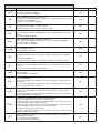
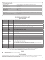
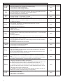
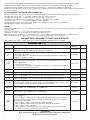
1
L8542518 06/2012 rev 3 CP.ZED230-E UNIONE NAZIONALE COSTRUTTORI AUTOMATISMI PER CANCELLI, PORTE SERRANDE ED AFFINI 1 16 15 14 13 12 11 10 9 8 7 6 GND 24 23 22 21 20 19 18 17 2 1 1 230Vac L 50Hz N 5 4 3 2 GND LAMP. 230VAC 3 RADIO ENCODER CM CM F1 315mA M2 F2 230V:F5A 115V:F10A M1 4 5 Light Service 6 U5 M2 M1 COM Light Service 7 8 COM 9 SWO 10 SWC 11 STOP 12 PHOT 13 OPEN 14 CLOSE 15 P.P. 16 24Vac 1A max 17 18 19 AUX 20 21 DAS 22 8k2 ANT SHIELD 23 ANT 24 3 2 AUX:0 AUX:1 AUX:2 17 RX 18 SCA 3W max 19 19 20 20 TX 24Vac COM NC 24Vac N.O. SCA II° CH RADIO AUX:3 AUX:4 N L 4 )!' %(+! COM 9 10 11 PHOT SERVICE LIGHT 12 3 13 20 14 20 15 19 LAMP PHOTO TEST 18 19 16 LAMP 24 Vdc 24Vac 1A max 18 17 17 Relè 24Vac 18 17 19 20 Service Light 230Vac Dichiarazione CE di Conformità Dichiarazione in accordo alle Direttive 2004/108/CE(EMC); 2006/95/CE(LVD) Fabbricante: Automatismi Benincà SpA Indirizzo: Via Capitello, 45 - 36066 Sandrigo (VI) - Italia Dichiara che il prodotto: Centrale di comando CP.ZED230-E è conforme alle condizioni delle seguenti Direttive CE: • DIRETTIVA 2004/108/CE DEL PARLAMENTO EUROPEO E DEL CONSIGLIO del 15 dicembre 2004 concernente il ravvicinamento delle legislazioni degli Stati membri relative alla compatibilità elettromagnetica e che abroga la direttiva 89/336/CEE, secondo le seguenti norme armonizzate: EN 61000-6-2:2005, EN 61000-6-3:2007. • DIRETTIVA 2006/95/CE DEL PARLAMENTO EUROPEO E DEL CONSIGLIO del 12 dicembre 2006 concernente il ravvicinamento delle legislazioni degli Stati membri relative al materiale elettrico destinato ad essere adoperato entro taluni limiti di tensione, secondo le seguenti norme armonizzate: EN 60335-1:2002 + A1:2004 + A11:2004 + A12:2006 + A2:2006 + A13:2008; EN 60335-2-103:2003. se applicabile: • DIRETTIVA 1999/5/CE DEL PARLAMENTO EUROPEO E DEL CONSIGLIO del 9 marzo 1999 riguardante le apparecchiature radio e le apparecchiature terminali di telecomunicazione e il reciproco riconoscimento della loro conformità, secondo le seguenti norme armonizzate: ETSI EN 301 489-3 V1.4.1 (2002) + ETSI EN 301 489-1 V1.4.1 (2002) + ETSI EN 300 220-3 V1.1.1 (2000) + EN 60950-1 (2001) Benincà Luigi, Responsabile legale. Sandrigo, 02/11/2010. AVVERTENZE Questo manuale è destinato esclusivamente a personale qualificato per l’installazione e la manutenzione di aperture automatiche. Nessuna informazione qui presente è di interesse o di utilità per l’utente finale. Conservare questo manuale per futuri utilizzi. L’installatore deve fornire tutte le informazioni relative al funzionamento automatico, manuale e di emergenza dell'automazione, e consegnare all’utilizzatore dell’impianto le istruzioni d’uso. Prevedere sulla rete di alimentazione un interruttore/sezionatore onnipolare con distanza d’apertura dei contatti uguale o superiore a 3 mm. Verificare che a monte dell’impianto elettrico vi sia un interruttore differenziale e una protezione di sovracorrente adeguati. Alcune tipologie di installazione richiedono il collegamento dell'anta ad un impianto di messa a terra rispondente alle vigenti norme di sicurezza. • L’installazione elettrica e la logica di funzionamento devono essere in accordo con le normative vigenti. I conduttori alimentati con tensioni diverse, devono essere fisicamente separati, oppure devono essere adeguatamente isolati con isolamento supplementare di almeno 1 mm. I conduttori devono essere vincolati da un fissaggio supplementare in prossimità dei morsetti. Durante gli interventi di installazione, manutenzione e riparazione, togliere l’alimentazione prima di accedere alle parti elettriche. Ricontrollare tutti i collegamenti fatti prima di dare tensione. Gli ingressi N.C. non utilizzati devono essere ponticellati. Le descrizioni e le illustrazioni presenti in questo manuale non sono impegnative. Lasciando inalterate le caratteristiche essenziali del prodotto il fabbricante si riserva il diritto di apportare qualsiasi modifica di carattere tecnico, costruttivo o commerciale senza impegnarsi ad aggiornare la presente pubblicazione. 5 DATI TECNICI Alimentazione centrale di comando 230 Vac 50/60 Hz oppure 115Vac 50/60Hz a seconda della versione Uscita Motore 1 o 2 motori 230Vac Potenza massima motore 300+300 W Uscita alimentazione accessori 24Vac 1A max. Grado di protezione IP54 Temp. funzionamento -20°C / +70°C Ricevitore radio 433,92 MHz incorporato e confgurabile (rolling-code o fisso+rolling-code) N° codici memorizzabili 64 Centrale di comando CP.ZED230-E COLLEGAMENTI ELETTRICI Nella seguente tabella sono descritti i collegamenti elettrici rappresentati in Fig. 1: N° Morsetti Funzione Descrizione 1-2 Alimentazione Ingresso 230Vac 50Hz (1-Fase/2-Neutro) 3-4 Lampeggiante Collegamento lampeggiante 230Vac 40W max. 4-5 Luce Motore Collegamento alla luce di cortesia (230Vac 40+40W max). 6-7-8 Motore 1/2 Collegamento al motore 1/2 : (6-marcia/7-Com/8-marcia) Nel caso di utilizzo di 2 motori collegare il secondo motore in parallelo*. 9 COM Comune per finecorsa e tutti gli ingressi di comando. 10 SWO Ingresso finecorsa APRE (contatto N.C.) 11 SWC Ingresso finecorsa CHIUDE (contatto N.C.) 12 STOP Ingresso pulsante STOP (contatto N.C.) 13 PHOT Ingresso collegamento dispositivi di sicurezza, contatto N.C. (ad es. fotocellule) 14 OPEN Ingresso pulsante APRE (contatto N.O.) 15 CLOSE Ingresso pulsante CHIUDE (contatto N.O.) 16 Passo-Passo Ingresso pulsante passo-passo (contatto N.O.) 17-18 24 Vac Uscita alimentazione accessori 24Vac/1A max. 19-20 AUX Contatto N.O. libero da tensione, configurabile come SCA/II°CH/PHOTO TEST. 21-22 COSTA Ingresso contatto costa sensibile Costa resistiva: Jumper “DAS” chiuso Costa meccanica: Jumper “DAS” aperto L’intervento della costa durante la fase di apertura arresta il movimento dell’anta. Durante la fase di chiusura arresta il movimento, inverte (apre) per 3s. 23-24 Antenna Collegamento antenna scheda radioricevente ad innesto (23-schermo/24-segnale). CM-CM Condensatore Collegamento condensatore motore J3 Radio Ricevente radio incorporata IMPORTANTE: *Nel caso di utilizzo di due motori, collegare alla centrale di comando i finecorsa di un solo motore. Il collegamento tra CP.ZED230-E e scheda ZED.SC è rappresentato in Fig.3 F1 Fusibile protezione uscita accessori e segnali. F2 Fusibile di protezione motore Fusibili Programmazione La programmazione delle varie funzionalità della centrale viene effettuata utilizzando il display LCD presente a bordo della centrale ed impostando i valori desiderati nei menu di programmazione descritti di seguito. 6 Il menu parametri consente di impostare un valore numerico ad una funzione, in modo analogo ad un trimmer di regolazione. Il menu logiche consente di attivare o disattivare una funzione, in modo analogo al settaggio di un dip-switch. Altre funzioni speciali seguono i menu parametri e logiche e possono variare a seconda del tipo di centrale o revisione software. UTILIZZO dei PULSANTI <PG>/<#>/<$> Premere il tasto <PG> per accedere alle impostazioni che si possono così modificare premendo i tasti # e $. • Premendo il tasto <#> si scorre all’interno del menù funzioni dal basso verso l’alto. • Premendo il tasto <$> si scorre all’interno del menù funzioni dall’alto verso il basso. • Premendo il tasto <PG> si può accedere alle eventuali impostazioni da modificare. • Con i tasti <#> e <$> si possono modificare i valori impostati. • Ripremendo il tasto <PG> il valore viene programmato, il display mostra il segnale “PRG”. Vedi paragrafo “Esempio Programmazione”. Note: La pressione simultanea di <#> e <$> effettuata all’interno di un menu funzione consente di tornare al menu superiore senza apportare modifiche. La pressione del pulsante <$> a display spento equivale ad un comando passo-passo. All’accensione della scheda viene visualizzata per circa 5s la versione software Mantenere la pressione sul tasto <#> o sul tasto <$> per accelerare l’incremento/decremento dei valori. Dopo un’attesa di 60s la centrale esce dalla modalità programmazione e spegne il display. Parametri, Logiche e Funzioni Speciali Nelle tabelle di seguito vengono descritte le singole funzioni disponibili nella centrale. PARAMETRI (PAR) MENU FUNZIONE MIN-MAX-(Default) Tempo di chiusura automatica. Attivo solo con logica “TCA”=ON. Al termine del tempo impostato la centrale comanda una manovra di chiusura. 1-240-(40s) TM Tempo lavoro motore. Regola il tempo totale della corsa durante la fase di apertura e chiusura del motore. Con la logica ENC:ON, questo valore viene automaticamente impostato dalla procedura di autoregolazione dei parametri (AUTO). 2-180-(60s) TSM Regola lo spazio percorso dall’anta durante la fase di rallentamento in chiusura. Lo spazio di rallentamento in apertura è automaticamente impostato ad 1/4 dello spazio di rallentamento in chiusura. 0 = rallentamento disabilitato. Con logica ENC:OFF il valore è espresso in secondi, e imposta la durata del rallentamento dopo l’intervento del finecorsa. 0-99-(10%) PMo Regola la coppia applicata al motore durante la fase di apertura a velocità normale.* 1-99-(40%) PMC Regola la coppia applicata al motore durante la fase di chiusura a velocità normale.* 1-99-(40%) Pso Regola la coppia applicata al motore durante la fase di apertura a velocità rallentata.* 1-99-(40%) PsC Regola la coppia applicata al motore durante la fase di chiusura a velocità rallentata.* 1-99-(40%) TLS Regola il tempo di attivazione della luce di servizio. Con parametro :0, svolge la funzione di luce di zona, accesa a motore in movimento e durante pausa TCA, spenta a motore fermo. 0-240-(60s) TCA SEAV Regola la soglia di intervento del dispositivo antischiacciamento (Encoder) durante la fase a velocità normale.* 99: massima sensibilità - 0: minima sensibilità 0-99-(0%) SEAR Regola la soglia di intervento del dispositivo antischiacciamento (Encoder) durante la fase di rallentamento.* 99: massima sensibilità - 0: minima sensibilità 0-99-(0%) AUX Imposta la modalità di funzionamento dell’uscita ausiliaria ai morsetti 19/20. Vedi collegamenti in figura 2. 0: uscita configura come SCA (spia cancello aperto): Spenta a porta chiusa, accesa a porta aperta, lampeggiante lento in apertura e veloce in chiusura. 1: uscita configurata come II° canale radio della ricevente integrata. 2: uscita configurata come PHOT TEST (verifica fotocellula). 3: uscita configurata come uscita lampeggiante 4: uscita configurata come luce di servizio aggiuntiva a quella presente sul motoriduttore, il cui tempo di attivazione è regolato dal parametro TLS. 0-4-(0) * ATTENZIONE Un’errata impostazione di questi parametri può risultare pericolosa. Rispettare le normative vigenti! MEMO 7 LOGICHE (LOG) MENU ON-OFF-(Default) TCA Abilita o disabilita la chiusura automatica On: chiusura automatica abilitata Off: chiusura automatica disabilitata (OFF) IBL Abilita o disabilita la funzione condominiale. On: funzione condominiale abilitata. L’impulso P.P. o del trasmettitore non ha effetto durante la fase di apertura. Off: funzione condominiale disabilitata. (OFF) Seleziona la modalità di funzionamento del ”Pulsante P.P.” e del trasmettitore. On: Funzionamento: APRE > CHIUDE > APRE > Off: Funzionamento: APRE > STOP > CHIUDE > STOP > (OFF) PRE Abilita o disabilita il pre-lampeggio. On: Pre-lampeggio abilitato. Il lampeggiante si attiva 3s prima della partenza del motore. Off: Pre-lampeggio disabilitato. (OFF) BLC Abilita o disabilita la funzione di blocco in chiusura. Vedi paragrafo “Modalità di funzionamento con encoder Abilitato/Disabilitato” On: Funzione blocco abilitato. Off: Funzione blocco disabilitato. (ON) Abilita o disabilita il lampeggiante durante il tempo TCA. On: Lampeggiante attivo. Off: Lampeggiante non attivo. (OFF) SPN Attiva o disattiva la funzione di spunto con logica ENC:OFF. On: funzione abilitata, i primi 2s di manovra vengono effettuati con la coppia massima. Off: funzione disabilitata Con logica ENC:ON, lo spunto viene regolato automaticamente dalla centrale. (OFF) HTR Abilita o disabilita la funzione Uomo presente. On: Funzionamento Uomo Presente. La pressione dei pulsanti APRE/CHIUDE deve essere mantenuta durante tutta la manovra. Off: Funzionamento automatico/semiautomatico. (OFF) Abilita o disabilita i comandi PP e PED durante la fase TCA. On: Comandi PP e PED non abilitati. Off: Comandi PP e PED abilitati. (OFF) ENC Abilita o disabilita l’Encoder. On: Encoder abilitato. Off: Encoder disabilitato (da utilizzare con motori serie ZED non provvisti di Encoder integrato). NB: L’eventuale riabilitazione dell’Encoder (da OFF a ON) richiede una nuova procedura di Autotaratura (menu AUTO). (ON) CVAR Abilita o disabilita i trasmettitori a codice programmabile. On: Ricevitore radio abilitato esclusivamente ai trasmettitori a codice variabile (rolling-code). Off: Ricevitore abilitato a trasmettitori codice variabile (rolling-code) e programmabile (autoapprendimento e dip/switch) . (OFF) PHTo Seleziona la modalità di funzionamento dell’ingresso PHOT. On: Ingresso PHOT attivo sia in apertura sia in chiusura. In apertura: l’apertura del contatto provoca l’arresto del motore, quando la fotocellula viene liberata, il motore riparte in apertura. In chiusura: l’apertura del contatto provoca l’arresto del motore, quando la fotocellula viene liberata, il motore inverte il senso di marcia (apre). Off: Ingresso PHOT attivo solo in chiusura. In chiusura: l’apertura del contatto provoca l’arresto del motore e l’inversione istantanea del senso di marcia (apre). (OFF) Abilita o disabilita l’inserimento remoto dei radiotrasmettitori (vedi paragrafo APPRENDIMENTO REMOTO). On: Inserimento remoto abilitato Off: Inserimento remoto disabilitato. (OFF) PP LTCA IBCA REM 8 FUNZIONE MEMO RADIO (RAD) MENU PP FUNZIONE Selezionando questa funzione la ricevente si pone in attesa (Push) di un codice trasmettitore da assegnare alla funzione passo-passo. Premere il tasto del trasmettitore che si intende assegnare a questa funzione. Se il codice è valido, viene memorizzato e viene visualizzato il messaggio OK Se il codice non è valido, viene visualizzato il messaggio Err. 2Ch Con parametro AUX:1 effettua la funzione di II° canale radio ai morsetti 19/20. Con parametro AUX:0 e AUX:2, effettua l’attivazione della luce di servizio secondo il tempo impostato dal parametro TLS. Selezionando questa funzione la ricevente si pone in attesa (Push) della pressione del tasto da associare a tale funzione. Se il codice è valido, viene memorizzato e viene visualizzato il messaggio OK Se il codice non è valido, viene visualizzato il messaggio Err. CLR Selezionando questa funzione la ricevente si pone in attesa (Push) di un codice trasmettitore da cancellare dalla memoria. Se il codice è valido, viene cancellato e viene visualizzato il messaggio OK Se il codice non è valido o non è presente in memoria, viene visualizzato il messaggio Err RTR Cancella completamente la memoria della ricevente. Viene richiesta conferma dell’operazione. NUMERO MANOVRE (Nman) Visualizza il numero di cicli completi (apre+chiude) effettuate dall’automazione. La prima pressione del pulsante <PG>, visualizza le prime 4 cifre, la seconda pressione le ultime 4. Es. <PG> 0012 >>> <PG> 3456: effettuati 123.456 cicli. CICLI MANUTENZIONE (maci) Questa funzione consente di attivare la segnalazione di richiesta manutenzione dopo un numero di manovre stabilito dall’installatore. Per attivare e selezionare il numero di manovre, procedere come segue: Premere il pulsante <PG>, il display viusalizza OFF, che indica che la funzione è disabilitata (valore di default). Con i pulsanti <+> e <-> selezionare uno dei valori numerici proposti (da OFF a 100). I valori vanno intesi come centinaia di cicli di manovre (ad es.: il valore 50 sta ad indicare 5000 manovre). Premere il pulsante OK per attivare la funzione. Il display visualizza il messaggio PROG. La richiesta di manutenzione viene segnalata all’utente con il lampeggio dei LED della luce di cortesia durante la manovra di apertura e chiusura. RESET (RES) RESET della centrale. ATTENZIONE!: Riporta la centrale ai valori di default. La prima pressione del pulsante <PG> provoca il lampeggio della scritta RES, una ulteriore pressione del pulsante <PG> effettua il reset della centrale. Nota: Non vengono cancellati i trasmettitori dalla ricevente, ne la posizione e la corsa dell’anta. PASSWORD DI ACCESSO (CODE) Consente di inserire un codice di protezione di accesso alla programmazione della centrale. E’ possibile inserire un codice alfanumerico di quattro caratteri utilizzando i numeri da 0 a 9 e le lettere A-B-C-D-E-F. Il valore di default è 0000 (quattro zeri) e indica l’assenza di codice di protezione. Sostituendo il codice 0000 con qualsiasi altro codice si abilita la protezione della centrale, impedendo l’accesso a tutti i menu. Se si desidera inserire un codice di protezione, procedere come segue: - selezionare il menu Code e premere OK. - viene visualizzato il codice 0000, anche nel caso sia già stato inserito in precedenza un codice di protezione. - con i tasti + e - si può variare il valore del carattere lampeggiante. - con il tasto OK si conferma il carattere lampeggiante e si passa al successivo. - dopo aver inserito i 4 caratteri compera un messaggio di conferma “CONF”. - dopo alcuni secondi viene ri-visualizzato il codice 0000 - è necessario riconfermare il codice di protezione precedentemente inserito, in modo da evitare inserimenti involontari. Se il codice corrisponde al precedente, viene visualizzato un messaggio di conferma “OK” La centrale esce automaticamente dalla fase di programmazione, e per accedere nuovamente ai menu sarà necessario inserire il codice di protezione memorizzato. In qualsiasi momento è possibile annullare l’operazione di inserimento del codice, premendo contemporaneamente i tasti + e -. Una volta inserita la password è possibile operare sulla centrale, entrando ed uscendo dalla programmazione per un tempo di circa 10 minuti, in modo da consentire le operazioni di regolazione e test delle funzioni. IMPORTANTE: ANNOTARE il codice di protezione e CONSERVARLO IN LUOGO SICURO per future manutenzioni. Per rimuovere un codice da una centrale protetta è sufficente riportare il codice al valore di default 0000. IN CASO DI SMARRIMENTO DEL CODICE È NECESSARIO RIVOLGERSI ALL’ASSITENZA TECNICA AUTORIZZATA, PER IL RESET TOTALE DELLA CENTRALE. 9 INSTALLAZIONE La centrale CP.ZED230E può essere utilizzata con diverse versioni del motoriduttore ZED: ZED con 2 finecorsa (apertura e chiusura). ZED con 1 finecorsa (solitamente utilizzato come finecorsa di apertura o per funzioni ausiliarie) ZED senza finecorsa Nel caso di assenza di uno o più finecorsa, l’arresto della manovra verrà gestito dalla centrale dopo aver memorizzato le posizioni di apertura/chiusura. La procedura di seguito descritta è valida per tutte le versioni: 1) Dare alimentazione alla centrale 2) Sbloccare manualmente e chiudere completamente la porta. 3) Se presente, regolare la camma del finecorsa di chiusura, il segmento del display SWC si accende (vedi paragrafo “Diagnostica”), nel caso si accendesse il segmento SWO, invertire i fili dei finecorsa SWO<>SWC. 4) Portare la porta nella posizione di apertura desiderata, prevedendo qualche cm di extracorsa. 5) Se presente, regolare la camma del finecorsa di apertura, il segmento del display SWO si accende. 6) Ribloccare la porta. 7) Dare avvio ad una manovra di autoset: - Premere PGM, selezionare con i pulsanti <#> e <$> il menu AUTO. - Premere PGM, la scritta AUTO inizia a lampeggiare. - Premere nuovamente PGM, appare la scritta “UP”. - Se la porta non si trova nella posizione di apertura desiderata, premere e mantenere premuto il pusante <#> per aprire la porta o il pulsante <$> per chiuderla, rilasciare il pulsante nel punto di apertura da memorizzare. Note: - se la pressione del pulsante <#> provoca la chiusura della porta, significa che il collegamento del motore non è corretto, invertire tra loro i fili di marcia (6<>8) e ripetere la procedura dal punto 7. - la regolazione della posizone di apertura avviene in modalità UOMO PRESENTE, sono pertanto disattivate tutte le sicurezze. E’ possibile anche utilizzare un trasmettitore precedentemente memorizzato in alternativa ai pulsanti <#> e <$>. - Premere nuovamente PGM, per iniziare la procedura di autoapprendimento, viene visualizzato il messaggio PRG. La centrale comanda una manovra di completa chiusura seguita da una manovra di apertura e da una di chiusura. - Al termine della procedura il display visualizza il messaggio OK. NB: Se compare il messaggio di errore “ERR” durante la fase di autoset, vedere paragrafo “Messaggi di errore”. Uscire dalla programmazione premendo simultaneamente i tasti # e $ oppure attendendo 30 secondi (time-out). Modalità di funzionamento con Encoder abilitato/disabilitato Con LOGICA ENC=ON: - il sensore antischiacciamento è attivato. Regolare la sensibilità tramite i parametri SEAV e SEAR in conformità con le normative vigenti. Acquisita la corsa la centrale gestirà in modo automatico le fasi di rallentamento in apertura e chiusura. Lo spazio di rallentamento può essere aumentato o diminuito dal parametro TSM. La corsa viene costantemente aggiornata e salvata in memoria assieme alla posizione del cancello in caso di mancanza rete. Se la logica BLC è ON trascorso il tempo di rallentamento TSM, nel momento in cui viene intercettato il finecorsa, viene ritardato l’arresto di circa 1s. Con LOGICA ENC=OFF (Da utilizzare con motori sprovvisti di encoder): - il sensore antischiacciamento è disattivato. - se il parametro TSM>0 (rallentamento attivato), la centrale inizia la fase di rallentamento dopo aver intercettato il finecorsa con la durata impostata tramite il parametro stesso. NB: impostare il parametro TM per un valore superiore alla durata della corsa. La logica BLC in questa condizione è ininfluente. APPRENDIMENTO REMOTO TRASMETTITORI Se si dispone di un trasmettitore già memorizzato nella ricevente è possibile effettuare l’apprendimento radio remoto (senza necessità di accedere alla centrale). IMPORTANTE: La procedura deve essere eseguita con ante in apertura durante la pausa TCA. Procedere come segue: 1 Premere il tasto nascosto del trasmettitore già memorizzato. 2 Premere, entro 5s, il tasto del trasmettitore già memorizzato corrispondente al canale da associare al nuovo trasmettitore. Il lampeggiante si accende. 3 Premere entro 10s il tasto nascosto del nuovo trasmettitore. 4 Premere, entro 5s, il tasto del nuovo trasmettitore da associare al canale scelto al punto 2. Il lampeggiante si spegne. 5 La ricevente memorizza il nuovo trasmettitore ed esce immediatamente dalla programmazione. 10 Diagnostica Ad ogni ingresso è associato un segmento del display che in caso di attivazione si accende, secondo il seguente schema. Gli ingressi N.C. sono rappresentati dai segmenti verticali. Gli ingressi N.O. sono rappresentati dai segmenti orizzontali. SWO SWC P.P. OPEN CLOSE STOP PHOT DAS Messaggi di errore La centrale verifica il corretto funzionamento dei dispositivi di sicurezza. In caso di malfunzionamento possono essere visualizzati dal display i seguenti messaggi: ERR Errore auto apprendimento corsa: - attivazione di qualsiasi ingresso da parte dell’utente - anta in finecorsa di chiusura - logica HTR:ON - memorizzazione telecomandi ERR1 Verifica integrità circuito di gestione motore fallita ERR2 Errore PHOTO TEST ERR3 Encoder guasto. SMALTIMENTO Qualora il prodotto venga posto fuori servizio, è necessario seguire le disposizioni legislative in vigore al momento per quanto riguarda lo smaltimento differenziato ed il riciclaggio dei vari componenti (metalli, plastiche, cavi elettrici, ecc.). E’ consigliabile contattare il vostro installatore o una ditta specializzata ed abilitata allo scopo. 11 EC Declaration of conformity Declaration pursuant to Directives 2004/108/EC(EMC); 2006/95/EC(LVD) Manufacturer: Automatismi Benincà SpA Address: Via Capitello, 45 - 36066 Sandrigo (VI) - Italy Declares that the product: Control unit CP.ZED230-E is compliant with the conditions of the following EC Directives: • DIRECTIVE 2004/108/EC OF THE EUROPEAN PARLIAMENT AND COUNCIL of December 15 2004 regarding the approximation of the legislations of the member States relative to electromagnetic compatibility and that repeals directive 89/336/CEE, according to the following concurred norms: EN 61000-6-2:2005, EN 61000-6-3:2007. • DIRECTIVE 2006/95/EC OF THE EUROPEAN PARLIAMENT AND THE COUNCIL of December 12 2006 concerning the approximation of the legislations of the member States relative to electrical material destined to be used within certain voltage limits, according to the following concurred regulations: EN 60335-1:2002 + A1:2004 + A11:2004 + A12:2006 + A2:2006 + A13:2008; EN 60335-2-103:2003. if applicable : • DIRECTIVE 1999/5/EC OF THE EUROPEAN PARLIAMENT AND THE COUNCIL of March 9 1999 regarding radio devices and terminal and telecommunications devices and the reciprocal recognisances of their conformity, according to the following concurred regulations: ETSI EN 301 489-3 V1.4.1 (2002) + ETSI EN 301 489-1 V1.4.1 (2002) + ETSI EN 300 220-3 V1.1.1 (2000) + EN 60950-1 (2001) Benincà Luigi, Legal manager. Sandrigo, 02/11/2010. WARNINGS This manual has been especially written to be use by qualified fitters. None of the information provide in this manual can be considered as being of interest for the end users. Preserve this manual for future needs. The technician has to furnish all the information related to the step by step function, the manual and the emergency function of the operator, and to deliver the manual to the final user. Foresee on the supply net an onnipolar switch or selector with distance of the contacts equal or superior to 3 mms. Verify that of the electrical system there is an awry differential interrupter and overcurrent protection. Some typologies of installation require the connection of the shutter to be link at a conductive mass of the ground according to the regulations in force. • 12 The electrical installation and the operating logic must comply with the regulations in force. The leads fed with different voltages must be physically separate, or they must be suitably insulated with additional insulation of at least 1 mm. The leads must be secured with an additional fixture near the terminals. During installation, maintenance and repair, interrupt the power supply before opening the lid to access the electrical parts Check all the connections again before switching on the power. The unused N.C. inputs must be bridged. The descriptions and the present illustrations in this manual are not binding. Leaving the essential characteristics of the product unchanged, the manufacturer reserves himself the right to bring any change of technical, constructive or commercial character without undertaking himself to update the present publication. TECHNICAL DATA Contol unit supply 230 Vac 50/60 Hz or 115Vac 50/60Hz according to the version Output supply 1/2 motor 230Vac Power maximum motor 300+300 W Output supply accessories 24Vac 1Amax. Protection level IP54 Operating temp. -20°C / +70°C Radio receiver built in 433,92 MHz confgurabile (rolling-code or programmable + rolling-code) Rolling code transmitters supported 64 rolling-code CP.ZED230-E CONTROL UNIT WIRE DIAGRAM Wire connections shown in Fig. 1 are described hereunder: Terminal No. Function Description 1-2 Power supply Input, 230VAC 50Hz (1-Phase/2-Neutral) 3-4 Flashing light Connection of flashing light, 230Vac 40W max. 4-5 Motor light Connection to the courtesy light (230VAC 40+40W max.). 6-7-8 Motor 1/2 Connection to motor 1/2 : (6-speed/7-Com/8-speed)* Should 2 motors be used, connect the second motor in parallel. 9 COM Common for limit switch and all control inputs. 10 SWO Input, OPEN limit switch (N.C. contact) 11 SWC Input, CLOSE limit switch (N.C. contact) 12 STOP Input, STOP push button (N.C. contact) 13 PHOT Input, connection to safety devices, N.C. contact (e.g. Photocells) 14 OPEN Input, OPEN push button (N.O. contact) 15 CLOSE Input, CLOSE push button (N.O. contact) 16 Step-by-Step Input, step-by-step push button (N.O. contact) 17-18 24 Vac Output, power supply of accessories, 24Vac/1A max. 19-20 AUX Normally Open (N.O.) contact, not powered, configurable as SCA/II°CH/PHOTO TEST. 21-22 COSTA Input, safety edge contact Resistive edge: Closed “DAS” jumper Mechanical edge: Open “DAS” jumper If the safety edge is activated in the opening phase, the gate stops. In the closing phase, the gate stops and the performs a movement reversion (opens) for 3s. 23-24 Aerial Connection to the radio receiver card of the aerial (23-screen/24-signal). CM-CM Capacitor Connected to motor capacitor J3 Radio receiver Built-in radio receiver IMPORTANT: Should two motors be used, connect the limit switches of one single motor to the control unit. The connection between CP.ZED230-E and the ZED.SC card is shown in Fig.3. Fuses F1 F2 Output protection fuse of accessories and signals Motor protection fuse PROGRAMMING The programming of the various functions of the control unit is carried out using the LCD display on the control unit and setting the desired values in the programming menus described below. The parameters menu allows you to assign a numerical value to a function, in the same way as a regulating trimmer. 13 The logic menu allows you to activate or deactivate a function, in the same way as setting a dip-switch. Other special functions follow the parameters and logic menus and may vary depending on the type of control unit or the software release. USE OF PROGRAMMING KEYS Press <PG> key to gain access to the Main Menu. These keys can be selected by pressing # and $ keys. • If <#> is pressed, the Function Menu can be scrolled from top to bottom. • If <$> is pressed, the Function Menu can be scrolled from bottom to top. • If <PG> key is pressed, presetting to be modified can be entered. • The preset values can be modified by using <#> and <$> keys. • The value is programmed if <PG> key is pressed again. The word “PRG” appears on the display. See paragraph “Programming Example”. NOTES: Simultaneously pressing <#> and <$> from inside a function menu allows you to return to the previous menu without making any changes. If the push-button <$> is pressed with display off, this is like giving a step-by-step control. When the board is switched on, the software version is displayed for around 5 sec Hold down the <#> key or the <$> key to accelerate the increase/decrease of the values. After waiting 60s the control unit quits programming mode and switches off the display. ParametERS, LOGICS AND SPECIAL FUNCTIONS In the tables hereunder the single functions available in the control unit are shown. PARAMETERS (PAR) MENU FUNCTION Automatic closure time. It is activated only with “TCA”=ON logic. At the end of the preset time, the control unit controls a closure operation. 1-240-(40s) Motor operating time. The total stroke time in the motor opening and closing phases is adjusted. With the ENC:ON logics, this value is automatically preset by the parameter selfadjustment procedure (AUTO). 2-180-(60s) Tsm The space covered by the dooe leaf during braking in the closing phase is adjusted. Braking in the opening phase is automatically preset at 1/4 of the closing space. 0 = braking is disabled. With ENC:OFF logics the value is expressed in seconds. Braking after the triggering of the limit switch is adjusted. 0-99-(10%) PMo The torque applied to the motor in the opening phase is adjusted.* 1-99-(40%) PMC The torque applied to the motor in the closing phase is adjusted *. 1-99-(40%) Pso The torque applied to the motor during braking in the closing phase is adjusted.* 1-99-(40%) Psc The torque applied to the motor during braking in the opening phase is adjusted * 1-99-(40%) TLS The activation time of the service light is adjusted. With parameter :0, the area light function is activated. The light is switched on when the motor is moving and during the TCA dwell time. The light switches off when the motor stops. 0-240-(60s) SEAV The triggering threshold of the anti-crash device (Encoder) during the normal speed phase.* 99: maximum sensitivity - 0: minimum sensitivity 0-99-(0%) SEAR The triggering threshold of the anti-crash device (Encoder) during braking.* 99: maximum sensitivity - 0: minimum sensitivity 0-99-(0%) TCA TM AUX The operating mode of the auxiliary output to terminals 19/20 is preset. See wire connections in figure 2. 0: output configurated as SCA (open gate indicator light): Off with closed door, on with open door, slow flash during opening, rapid flash during closing. 1: output configurated as radio channel II integrated receiver. 2: output configurated as PHOT TEST (photocell test). 3: output configurated as flashing light. 4: output configurated as service light additional to the light on the geared motor. Its activation time is adjusted by TLS parameter. * WARNING: An incorrect setting of these parameters may cause danger. Please comply with regulations in force! 14 MIN-MAX-(Default) 0-4-(0) MEMO LOGIC (LOG) MENU FUNCTION ON-OFF(Default) TCA The automatic closure is enabled or disabled On: enabled automatic closure Off: disabled automatic closure (OFF) IbL The multi-flat function is enabled or disabled. On: enabled multi-flat function. The P.P. (Step-by-step) impulse or the impulse of the transmitter have no effect in the opening phase. Off: disabled multi-flat function. (OFF) The operating mode of “P.P. Push button” and of the transmitter are selected. On: Operation : OPEN > CLOSE > OPEN > Off: Operation: OPEN > STOP > CLOSE > STOP > (OFF) PRE Forewarning flashing light enabled or disabled. On: enabled forewarning flashing light. The flashing light is activated 3 s before the starting of the motor. Off: disabled forewarning flashing light. (OFF) blc The lock function in the closing phase is enabled or disabled. See paragraph “Operating mode with Enabled/Disabled encoder”. On: Lock function is enabled. Off: Lock function is disabled. (ON) During the TCA time, the blinker is enabled or disabled. On: Activated blinker. Off: De-activated blinker. (OFF) spn The pick-up function with ENC:OFF logics is activated or deactivated. On: the function is enabled. The first two seconds of operation are carried out at maximum torque. With ENC:ON logics, pick-up is automatically adjusted by the control unit. (OFF) htr The Operator function is enabled or disabled. On: Operator function enabled. During operation, the OPEN/CLOSE push-buttons must be kept pressed. Off: Automatic/semiautomatic operation. (OFF) IBCA During the TCA phase, the PP and PED controls are enabled or disabled. On: PP and PED controls are disabled. Off: PP and PED controls are enabled. (OFF) ENC The Encoder is enabled or disabled. On: Enabled encoder. Off: Disabled encoder (to be used with ZED series motors that are not equipped with built-in Encoder). NB: The Encoder can be possibly reset (from OFF to ON). A new self-calibration procedure is required (AUTO menu). (ON) CVAR The code programmable transmitters is enabled or disabled. On: Radio receiver enabled only for rolling-code transmitters. Off: Receiver enabled for rolling-code and programmable code transmitters (self-learning and Dip Switch). (OFF) PHTo The operating mode of the PHOT input is selected. On: PHOT input is activated in both opening and closing. In the opening phase: when the contact is opened, the motor stops. When the photocell is released, the motor restarts with an opening movement. In the closing phase: when the contact is opened, the motor stops. When the photocell is released, the motor inverts its movement direction (opens). Off: PHOT input is activated only in the closing phase. In the closing phase: when the contact is opened, the motor stops and the movement direction is immediately reversed (opens). (OFF) rem The remote storage of the radio transmitter codes is enabled or disabled (see par. REMOTE LEARNING). On: Enabled remote storage Off: Disabled remote storage. (OFF) PP ltca MEMO 15 RADIO (RAD) MENU FUNZIONE PP By selecting this function, the receiver awaits (Push) for a transmitter code to be assigned to the step-by-step function. Press the transmitter key to be assigned to this function. If the code is valid, it is stored in memory and OK appears. If the code is not valid, the wording Err is displayed. 2Ch With AUX:1 parameter, the radio channel II function to terminals 19/20 is activated. With AUX:0 e AUX:2 parameter, the service light is activated according to the time preset by TLS parameter. By selecting this function, the receiver awaits (Push) the pressure of the key to be matched with that function. If the code is valid, the same is memorised and the OK message is displayed. If the code is not valid, the Err message is displayed. CLR By selecting this function, the receiver awaits (Push) for a transmitter code to be erased from memory. If the code is valid, it is erase and OK appears. If the code is not valid or is not in memory, the wording Err is displayed. RTR Completely erase the receiver memory. Confirmation of operation is required. CYCLES NUMBER (Nman) Displays the number of complete cycles (open+close) carried out by the automation. When the <PG> button is pressed for the first time, it displays the first 4 figures, the second time it shows the last 4. Example <PG> 0012 >>> <PG> 3456: made 123.456 cycles. MAINTENANCE CYCLES (maci) This function enables to activate the maintenance request notice after a number of manoeuvres determined by the installer. To activate and select the number of manoeuvres, proceed as follows: Press button <PG>, the display will show OFF, which indicated that the function is disabled (default value). With the buttons <+> and <-> select one of the numeric values proposed (from OFF to 100). The values are intended as hundreds of cycles of manoeuvres (for example: the value 50 indicates 5000 manoeuvres). Press the OK button to activate the function. The display will show the message PROG. The maintenance request is indicated to the user by keeping the indicator lamp lit up for other 10 sec after the conclusion of the opening or closing operation. The warning of maintenance required is indicated to the user through the flashing of the courtesy light LEDs during the opening and closing phases. RESET (RES) RESET of the control unit. ATTENTION!: Returns the control unit to the default values. Pressing the <PG> button for the first time causes blinking of the letters RES, pressing the <PG> button again resets the control unit. Note: The transmitters are not erased from the receiver nor is the access password. PROTECTION CODE (CODE) It allows to type in an access protection code to the programming of the control unit. A four-character alphanumeric code can be typed in by using the numbers from 0 to 9 and the letters A-B-C-D-E-F. The default value is 0000 (four zeros) and shows the absence of a protection code. While typing in the code, this operation can be cancelled at any moment by pressing keys + and – simultaneously. Once the password is typed in, it is possible to act on the control unit by entering and exiting the programming mode for around 10 minutes in order to allow adjustments and tests on functions. By replacing the 0000 code with any other code, the protection of the control unit is enabled, thus preventing the access to any other menu. If a protection code is to be typed in, proceed as follows: - select the Code menu and press OK. - the code 0000 is shown, also in the case a protection code has been previously typed in. - the value of the flashing character can be changed with keys + and -. - press OK to confirm the flashing character, then confirm the following one. - after typing in the 4 characters, a confirmation message “CONF” appears. - after a few seconds, the code 0000 appears again - the previously stored protection code must be reconfirmed in order to avoid any accidental typing in. If the code corresponds to the previous one, a confirmation message “OK” appears. The control unit automatically exits the programming phase. To gain access to the Menus again, the stored protection code must be typed in. IMPORTANT: TAKE NOTE of the protection code and KEEP IT IN A SAFE PLACE for future maintenance operations. To remove a code from a protected control unit it is necessary to enter into programming with the password and bring the code back to the 0000 default value. IF YOU LOOSE THE CODE, PLEASE CONTACT THE AUTHORISED SERVICE CENTER FOR THE TOTAL RESET OF THE CONTROL UNIT. 16 INSTALLATION The CP.ZED230E control unit can be used with various versions of the ZED gear motor: ZED with 2 limit switches (opening an closing). ZED with 1 limit switch (usually used as opening limit switch or auxiliary operations) ZED without limit switch If one or more limit switch are missing, the operation stop is controlled by the control unit after memorizing the opening/closing positions. The following procedure shall apply for all versions: 1) Power the control unit 2) Manually unlock and completely close the door. 3) If provided, adjust the closing limit switch cam, the SWC display segment switches on (see section “Diagnostics”). If the SWO segment switches on, invert the SWO<>SWC limit switch wires. 4) Move the door into the desired open position. Provide for some overrun centimetre. 5) If provided, adjust the opening limit switch cam. The SWO display segment switches on. 6) Lock the door again. 7) Start a self-test operation: - Press PGM, select the AUTO Menu with push-buttons <#> and <$> il menu AUTO. - Press PGM, the word AUTO starts flashing. - Press PGM agaom, the word “UP” is displayed. - If the door is not in the desired position, press and keep the <#> to open the door or <$> to sjut the door, release the pushbutton in the opening position to be stored in memory . Note: - if, by pressing <#>, the door closes, this means that the connection to the motor is incorrect. Therefore invert the operation wires (6<>8) and repeat the procedure from item 7. - the opening potizion can be adjusted in the SERVICE MAN mode; therefore, all safety devices are de-activated. A previously memorized transmitter can be used as an alternative to push-buttons <#> and <$>. - Press PGM again to start the self-learning procedure. The PRG message is displayed. The control unit controls a total closure operation, followed by an opening and closing operation. - At end of procedure, the message OK is displayed. NB.: If the “ERR” error message appears during the self-test phase, see section “Error messages”. Exit the programming mode by pressing keys <#> and <$> simultaneously, or by waiting for 30 seconds (time-out). OPERATING MODE WITH ENABLED/DISABLED Encoder With ENC=ON LOGICS: - the anti-crash sensor is activated. The sensitivity must be adjusted through the SEAV and SEAR parameters according to regulations in force. Once the stroke length is stored in memory by the control unit, the latter will automatically manage the braking phases during opening and closing. The braking space can be increased or decreased by the TSM parameter. The stroke is constantly updated and stored in memory together with the gate position in the event of power failure. If the BLOC logics is ON, after the TSM braking time has elapsed, the stop will be delayed by around 1s when the limit switch is triggered. With the ENC=OFF LOGICA (To be used with motors without encoder): - the anti-crash sensor is deactivated. - if the parameter TSM>0 (braking activated), the control unit starts the braking phase after triggering the limit switch. Duration is preset through the parameter itself. NB: Preset the TM parameter for a value higher than the stroke time. In this position, the BLOC logics is irrelevant. TRANSMITTER REMOTE LEARNING If the transmitter code is already stored in the receiver, the remote radio learning can be carried out (without accessing the control unit). IMPORTANT: The procedure should be carried out with gate in the opening phase, during the TCA dwell time. Proceed as follows: 1 Press the hidden key of the transmitter, the code of which has already been stored in memory. 2 Within 5 seconds, press the already memorised transmitter key corresponding to the channel to be matched to the new transmitter. The flashing light switches on. 3 Within 10 seconds, press the hidden key of the new transmitter. 4 Within 5 seconds, press the key of the new transmitter to be matched to the channel selected at item 2. The flashing light switches off. 5 The receiver stores the new transmitter code and exits from the programming mode immediately. 17 Diagnostics One segment of the display is linked to each input. In the event of failure it switches on according to the following scheme. N.C. inputs are represented by the vertical segments. N.O. inputs are represented by the horizontal segments. SWO SWC P.P. OPEN CLOSE STOP PHOT DAS ERROR MESSAGES The control unit checks the correct operation of the safety devices. In the event of failure, the following messages may be displayed: ERR Error, self-learning stroke: - activation of any input by the user - door leaf i the closing limit switch - HTR:ON logics - memorisation of remote controls ERR1 Check of management circuit integrity has failed ERR2 Error, PHOTO TEST ERR3 Encoder is broken. WASTE DISPOSAL If the product must be dismantled, it must be disposed according to regulations in force regarding the differentiated waste disposal and the recycling of components (metals, plastics, electric cables, etc..). For this operation it is advisable to call your installer or a specialised company. 18 EG-Konformitätserklärung Erklärung in Übereinstimmung mit der Richtlinie 2004/108/EG(EMC); 2006/95/EG(LVD) Hersteller: Automatismi Benincà SpA Adresse: Via Capitello, 45 - 36066 Sandrigo (VI) - Italien Erklärt, dass das Produkt: Steuerzentrale CP.ZED230-E mit mit den Bedingungen folgender EG-Richtlinien übereinstimmt: • RICHTLINIE 2004/108/EG DES EUROPAPARLAMENTS UND DES EUROPARATS vom 15. Dezember 2004 hinsichtlich der Anpassung der Rechtslage der Mitgliedsstaaten zur elektromagnetischen Verträglichkeit und zur Aufhebung der Richtlinie 89/336/EWG, nachfolgenden harmonisierenden Normen: EN 61000-6-2:2005, EN 61000-6-3:2007. • RICHTLINIE 2006/95/EG DES EUROPAPARLAMENTS UND DES EUROPARATS vom 12. Dezember 06 hinsichtlich der Anpassung der Rechtslage der Mitgliedsstaaten bezüglich in diesen Spannungsgrenzen benutzten Elektromaterials gemäß nachfolgender harmonisierenden Normen: EN 60335-1:2002 + A1:2004 + A11:2004 + A12:2006 + A2:2006 + A13:2008; EN 60335-2-103:2003. sofern anwendbar: • RICHTLINIE 1999/5/EG DES EUROPAPARLAMENTS UND DES EUROPARATS vom 9. März 1999 hinsichtlich Funkgeräte und Telekommunikationsendeinrichtungen und die gegenseitige Anerkennung ihrer Konformität gemäß folgender harmonisierender Normen: ETSI EN 301 489-3 V1.4.1 (2002) + ETSI EN 301 489-1 V1.4.1 (2002) + ETSI EN 300 220-3 V1.1.1 (2000) + EN 60950-1 (2001) Benincà Luigi, rechlich Verantwortlicher. Sandrigo, 02.11.2010. HINWEISE Dieses Handbuch ist ausschließlich qualifiziertem Personal für die Installation und Wartung von automatischen Öffnungsvorrichtungen bestimmt. Es enthält keine Informationen die für den Endbenutzer interessant oder nützlich sein könnten. Bewahren Sie dieses Handbuch für Nachschlagzwecke auf. Der Installateur hat dem Benutzer alle Informationen über den automatischen, manuellen und Not-Betrieb der Automatik zusammen mit der Bedienungsanleitung zu liefern. Das Stromnetz muss mit einem allpoligen Schalter bzw. Trennschalter ausgestattet sein, dessen Kontakte einen Öffnungsabstand gleich oder größer als 3 aufweisen. Kontrollieren ob der elektrischen Anlage ein geeigneter Differentialschalter und ein Überspannungsschutzschalter vorgeschaltet sind. Einige Installationstypologien verlangen den Anschluss des Flügels an eine Erdungsanlage laut den geltenden Sicherheitsnormen. • Die elektrische Installation und die Betriebslogik müssen den geltenden Vorschriften entsprechen. Die Leiter die mit unterschiedlichen Spannungen gespeist werden, müssen physisch getrennt oder sachgerecht mit einer zusätzlichen Isolierung von mindestens 1 mm isoliert werden. Die Leiter müssen in der Nähe der Klemmen zusätzlich befestigt werden. Während der Installation, der Wartung und der Reparatur, die Anlage stromlos machen bevor an den elektrischen Teilen gearbeitet wird. Alle Anschlüsse nochmals prüfen, bevor die Zentrale mit Strom versorgt wird. Die nicht verwendeten N.C. Eingänge müssen überbrückt werden. Die in diesem Handbuch enthaltenen Beschreibungen und Abbildungen sind nicht verbindlich. Ausgenommen der Haupteigenschaften des Produkts, behält sich der Hersteller das Recht vor eventuelle technische, konstruktive oder kommerzielle Änderungen vorzunehmen ohne dass er vorliegende Veröffentlichung auf den letzten Stand bringen muss. 19 TECHNICAL DATA Speisung der Steuereinheit 230 Vac 50/60 Hz oder 115Vac 50/60Hz je nach Ausführung Motorausgang 1/2 motor 230Vac Maximale Motorenleistung 300+300 W Ausgang Speisung Zubehör 24Vac 1A max. Schutzklasse IP54 Betriebstemperatur -20°C / +70°C Funkempfänger 433,92 MHz eingebaut und konfigurierbar (Rolling-Code oder fest+Rolling-Code) Programmierbare Codes 64 rolling-code STEUEREINHEIT CP.ZED230-E ELEKTRISCHE ANSCHLÜSSE In der nachstehenden Tabelle sind die elektrischen und in Abb. 1 dargestellten Anschlüsse beschrieben: Klemme Funktion Beschreibung 1-2 Speisung Eingang 230Vac 50Hz (1-Phase/2-Nulleiter) 3-4 Blinkleuchte Ausgang Anschluss Blinkleuchte 230Vac 40W max. 4-5 Motorenlicht Anschluss an die Höflichkeitsleuchte (230Vac 40+40W max). 6-7-8 Motor 1/2 Anschluss an den Motor 1/2 : (6-Betrieb/7-Com/8- Betrieb) Wenn 2 Motoren installiert werden, den zweiten parallel anschließen. 9 COM Gemein für alle Steuerungseingänge. 10 SWO Eingang Endschalter ÖFFNEN (Kontakt N.C.) 11 SWC Eingang Endschalter SCHLIESSEN (Kontakt N.C.) 12 STOPP Eingang STOPP-Taste (Kontakt N.C.) 13 PHOT Eingang zum Anschluss von Sicherheitsvorrichtungen, Kontakt N.C. (z.B. Photozellen) 14 OPEN Eingang Taste ÖFFNEN (Kontakt N.O.) 15 CLOSE Eingang Taste SCHLIESSEN (Kontakt N.O.) 16 Schritt-Schritt Eingang Taste Schritt-Schritt (Kontakt N.O.) 17-18 24 Vac Ausgang Zubehörspeisung 24Vac/1A max. 19-20 AUX Stromloser N.O. Kontakt, konfigurierbar als SCA/II°CH/PHOTO TEST. 21-22 FLANKE Eingang Kontakt Näherungsflanke Widerstandsfähige Flanke: Jumper “DAS” geschlossen Mechanische Flanke: Jumper “DAS” geöffnet Wenn die Flanke beim Öffnen eingeschaltet wird, hält die Flügelbewegung an. Beim Schließen wird die Bewegung angehalten und 3 sec. lang umgeschaltet (öffnen). 23-24 Antenne Anschluss Antenne der Karte des steckbaren Funkempfängers und des eingebauten Funkmoduls (23-Schirm/24-Signal). CM-CM Kondensator Anschluss Kondensator Motor J3 Funk Eingebauter Funkempfänger WICHTIG: Wenn zwei Motoren installiert werden, nur die Endschalter eines einzigen Motors an die Steuereinheit schließen. Die Verbindung zwischen CP.ZED230-E und Karte ZED.SC ist in der Abb. 3 dargestellt F1 F2 Motoren-Schutzsicherung Schutzsicherung Eingang Zubehör und Signale Sicherungen PROGRAMMIERUNG Die Programmierung der verschiedenen Funktionen der Zentrale erfolgt über das LCD Display an Bord der Zentrale indem die gewünschten Werte im Programmierungsmenü, wie nachstehend beschrieben eingerichtet werden. 20 Das Menü Parameter ermöglicht es einer Funktion einen numerischen Wert zuzuordnen, wie es bei einem Trimmer der Fall ist. Das Menü der Logik ermöglicht es eine Funktion zu aktivieren oder deaktivieren, ähnlich wie bei der Einstellung eines Dip-Schalters. In den Menüs Parameter und Logik können zudem noch andere Sonderfunktionen eingestellt werden, die je nach Modell oder SoftwareVersion unterschiedlich sind. GEBRAUCH DER PROGRAMMIERUNGSTASTEN Die Taste <PG> drücken, um das Hauptmenü abzurufen, dessen Optionen über die Tasten # und $ gewählt werden können. • Die Taste <#> drücken, um das Menü der Funktionen von oben nach unten abzurollen • Die Taste <$> drücken, um das Menü der Funktionen von unten nach oben abzurollen. • Durch Drücken der Taste <PG> kann man eventuelle Einstellungen ändern. • Mit den Tasten <#> und <$> kann man eingerichtete Werte ändern. • Drückt man nochmals die Taste <PG>, wird der Wert programmiert und am Display wird die Schrift „PRG“ angezeigt. Siehe Paragraph „Programmierungsbeispiel“. BEMERKUNGEN: Durch gleichzeitiges Drücken der Tasten <#> und <$> im Inneren des Menüs ‚Funktion’, kann man das vorhergehende Menü abrufen ohne Änderungen vorzunehmen. Das Drücken der Taste <$> bei ausgeschaltetem Display entspricht einer Schritt-Schritt Steuerung. Beim Einschalten der Karte wird ca. 5 s lang die Softwareversion angezeigt. Die Taste <#> oder <$> gedrückt halten, um die Zu-/Abnahme des Wertes zu beschleunigen. Das Drücken der Taste <$> bei ausgeschaltetem Display entspricht einem Impuls P.P. PARAMETER, LOGIK UND SONDERFUNKTIONEN In den nachstehenden Tabellen sind die einzelnen Funktionen der Zentrale beschrieben. PARAMETER (PAR) MENU FUNKTION MIN-MAX-(Default) Zeit für das automatische Schließen Aktiv nur mit Logik TCA= ON Wenn die eingestellte Zeit abgelaufen ist, steuert die Zentrale das Schließen. 1-240-(40s) TM Betriebszeit Motor. Regelt die gesamte Betriebszeit des Motors beim Öffnen und Schließen. Mit der Logik ENC:ON wird dieser Wert automatisch durch die Selbstlernfunktion der Parameter (AUTO) eingerichtet. 2-180-(60s) Tsm Regelt die Strecke entlang welcher, der Flügel den Schließvorgang verlangsamt. Die Strecke zur Geschwindigkeitsabnahme beim Öffnen wird automatisch auf 1/4 der Strecke eingestellt. 0 = Geschwindigkeitsabnahme deaktiviert Mit der Logik ENC:OFF wird der Wert in Sekunden ausgedrückt. Dieser bestimmt die Geschwindigkeitsabnahme nach Einschalten des Endschalters. 0-99-(10%) PMo Regelt das für den Motor angelegte Drehmoment beim Öffnen*. 1-99-(40%) PMC Regelt das für den Motor angelegte Drehmoment beim Schließen.* 1-99-(40%) Pso Regelt das für den Motor angelegte Drehmoment während der Geschwindigkeitsabnahme beim Öffnen.* 1-99-(40%) Psc Regelt das für den Motor angelegte Drehmoment während der Geschwindigkeitsabnahme beim Schließen.* 1-99-(40%) TLS Regelt die Aktivierungsdauer des Dienstlichtes. Mit dem Parameter :0 bleibt das Zonenlicht bei laufendem Motor eingeschaltet. Während der Pause TCA bei stillstehendem Motor bleibt es ausgeschaltet. 0-240-(60s) TCA SEAV Regelt die Schaltgrenze der Quetschsicherheitsvorrichtung (Encoder) während der normalen Geschwindigkeit*. 99: maximale Empfindlichkeit – 0: mindeste Empfindlichkeit 0-99-(0%) SEAR Regelt die Schaltgrenze der Quetschsicherheitsvorrichtung (Encoder) während der Geschwindigkeitsabnahme*. 99: maximale Empfindlichkeit – 0: mindeste Empfindlichkeit 0-99-(0%) AUX Regelt den Betriebsmodus des Hilfsausgangs an den Klemmen 19/20. Siehe Anschlüsse in Abbildung 2. 0: Ausgang als SCA (Leuchte für das offene Tor) konfiguriert. Bei geschlossener Tür ist die Leuchte ausgeschaltet, bei offener Tür ist sie eingeschaltet. Beim Öffnen blinkt sie langsam; beim Schließen blinkt sie schnell. 1: Ausgang als zweiter Funkkanal des integrierten Empfängers konfiguriert. 2: Ausgang als PHOT TEST (Fotozellentest) konfiguriert. 3: Ausgang als Blinkleuchte konfiguriert. 4: Ausgang der zusätzlich zum Dienstlicht des Getriebemotors als solches konfiguriert ist. Die entsprechende Aktivierungszeit wird über den Parameter TLS geregelt. 0-4-(0) MEMO * ACHTUNG: Eine falsche Einstellung dieser Parameter kann gefährlich sein. Die geltenden Vorschriften beachten! 21 LOGIKEN (LOG) MENU ON-OFF-(Default) TCA Aktiviert oder deaktiviert den automatischen Schließvorgang. On: automatischer Schließvorgang aktiviert Off: automatischer Schließvorgang deaktiviert (OFF) IbL Aktiviert oder deaktiviert die Funktion Wohngemeinschaft. On: Funktion Wohngemeinschaft aktiviert. Auf den Öffnungsvorgang haben weder der Schritt-Schritt-Impuls noch der Impuls des Sendegeräts Einfluss. Off: Funktion Wohngemeinschaft deaktiviert. (OFF) Wählt die Betriebsweise der “Taste P.P.” und des Sendegeräts. On: Betrieb: ÖFFNEN > SCHLIESSEN > ÖFFNEN Off: Betrieb: ÖFFNEN > STOP > SCHLIESSEN > STOP > (OFF) PRE Aktiviert oder deaktiviert das Vorblinken. On: Vorblinken aktiviert Das Vorblinken beginnt 3 sec. vor dem Einschalten des Motors. Off: Vorblinken deaktiviert (OFF) blc Aktiviert oder deaktiviert die Funktion Blockieren beim Schließen. Siehe Paragraph „Betriebsweise mit aktiviertem/deaktiviertem Encoder“. On: Funktion Blockierung aktiviert. Off: Funktion Blockierung deaktiviert. (ON) Aktiviert oder deaktiviert das Blinklicht während der Zeit TCA On: Blinklicht aktiv: Off: Blinklicht nicht aktiv. (OFF) spn Aktiviert oder deaktiviert die Funktion des Anlaufs mit Logik ENC:OFF. On: Funktion aktiviert. Die Bewegung erfolgt während der ersten 2 sec. bei maximalem Drehmoment. Off: Funktion deaktiviert. Mit der Logik ENC:ON, wird der Anlauf automatisch von der Zentrale eingerichtet. (OFF) htr Aktiviert oder deaktiviert die Funktion “Mann vorhanden”. On: Betrieb im Modus „Mann vorhanden“ Die Taste ÖFFNEN/SCHLIESSEN muss während der gesamten Dauer der Steuerung gedrückt bleiben. Off: Automatischer/halbautomatischer Betrieb. (OFF) Aktiviert oder deaktiviert die Steuerungen PP und PED während der Phase TCA. On: Steuerungen PP und PED nicht aktiviert. Off: Steuerungen PP und PED aktiviert. (OFF) PP LTCA IBCA 22 FUNKTION ENC Aktiviert oder deaktiviert den Encoder On: Encoder aktiviert. Off: Encoder deaktiviert (ist bei Motoren der Serie ZED erforderlich, da diese keinen integrierten Encoder besitzen). N.B.: Die erneute Aktivierung des Encoders (von OFF auf ON) muss über eine neue Selbsteichungsprozedur erfolgen (Menü AUTO). (ON) CVAR Aktiviert oder deaktiviert die Sendegeräte mit programmierbarem Code. On: Funkempfänger ist nur für Sendegeräte mit variablem Code aktiviert (RollingCode). Off: Funkempfänger ist für Sendegeräte mit variablem Code (Rolling-Code) und programmierbare (Selbstlernfunktion und Dip-Schalter) Sendegeräte aktiviert. (OFF) PHTo Wählt die Betriebsweise des Eingangs PHOT. On: Eingang PHOT aktiv beim Öffnen und Schließen. Beim Öffnen: Das Öffnen des Kontakts hat das Anhalten des Motors zur Folge, wenn die Fotozelle freigesetzt wird. Der Motor schaltet beim Öffnen wieder ein. Beim Schließen: Das Öffnen des Kontakts hat das Anhalten des Motors zur Folge, wenn die Fotozelle freigesetzt wird. Der Motor schaltet die Betriebsrichtung um (öffnet). Off: Eingang PHOT nur beim Schließen aktiv. Beim Schließen: Das Öffnen des Kontakts hat das Anhalten des Motors und das unmittelbare Umschalten der Betriebsrichtung zur Folge (öffnet). (OFF) rem Aktiviert oder deaktiviert das Einschalten von fern der Sendegeräte (siehe Paragraph LERNFUNKTION VON FERN). On: Einschalten von fern aktiviert Off: Einschalten von fern deaktiviert (OFF) MEMO RADIO (RAD) MENU PP 2Ch FUNZIONE Wird diese Funktion gewählt, wartet (Push) der Empfänger auf einen Sendercode der der Schritt-SchrittFunktion zugeteilt werden muss. Taste des Sendegeräts drücken, dem diese Funktion zugeteilt werden soll. Ist der Code gültig, wird dieser gespeichert und die Meldung OK angezeigt. Ist der Code ungültig, wird die Meldung Err angezeigt. Über den Parameter AUX:1 übernimmt die Vorrichtung die Funktion des zweiten Funkkanals an den Klemmen 19/20. Mit den Parametern AUX:0 und AUX:2 wird das Dienstlicht je nach eingestellter Zeit (Parameter TLS) aktiviert. Wird diese Funktion gewählt, wartet (Push) der Empfänger auf einen neuen Druck der Taste, der dieser Funktion zugeordnet wird. Ist der Code gültig, wird dieser gespeichert und die Meldung OK angezeigt. Ist der Code ungültig, wird die Meldung Err angezeigt. CLR Wird diese Funktion gewählt, wartet (Push) der Empfänger auf einen Sendercode der gelöscht werden muss. Ist der Code gültig, wird dieser gelöscht und die Meldung OK angezeigt. Ist der Code ungültig oder nicht gespeichert, wird die Meldung Err angezeigt. RTR Löscht den gesamten Speicher des Empfängers. Der Vorgang muss bestätigt werden. ZYKLEN (Nman) Zeigt die Zahl der von der Automatisierung ausgeführten kompletten Zyklen (Öffnen+Schließen) an. Beim erstmaligen Drücken der Taste <PG> erscheinen die ersten 4 Ziffern, beim zweiten Drücken die letzten 4. Beispiel <PG> 0012 >>> <PG> 3456: es wurden 123.456 Zyklen ausgeführt. WARTUNGSZYKLEN (maci) Diese Funktion ermöglicht es, nach einer Anzahl von stattgefundenen Manövern, die vom Installateur festgelegt werden, die erforderliche Wartungren. Zur Aktivierung und zur Auswahl der Manöver, gehen Sie wie folgt vor: Drücken der Taste <PG>, das Display zeigt OFF an, was heißt, dass die Funktion nicht zur Verfügung steht (Voreinstellung). Mit den Tasten <+> und <-> wählen Sie einen der vorgeschlagenen Werte (von OFF bis 100). Die Werte zeigen das Hundertfache der Manöverdurchgänge an (z.B.: steht der Wert 50 für 5000 Manöver). Drücken der Taste OK, um die Funktion zu aktivieren. Das Display zeigt die Meldung PROG an. Die Wartungsnachfrage wird dem Benutzer durch das 10 Sekunden lange Blinken nach beendeter Öffnung- oder Schließbewegung gemeldet. Die Wartungsnachfrage wird durch das Blinken der LEDs der Höflichkeitsleuchte während des Öffnens oder Schließens gemeldet. RESET (RES) RESET der Steuerzentrale. ACHTUNG!: Bringt die Zentrale auf die Default-Werte zurück. Beim erstmaligen Drücken der Taste <PG> blinkt die Schrift RES, beim weiteren Drücken der Taste <PG> erfolgt das Reset der Steuerzentrale. Anmerkung: Es werden weder die Sender vom Empfänger noch das Zugangspasswort gelöscht. SCHÜSSELCODE (CODE) Gestattet es einen Schüsselcode einzugeben, um den Zugriff auf die Programmierung der Einheit zu schützen. Der Code muss aus vier alphanumerischen Zeichen bestehen (0 bis 9 und/oder A-B-C-D-E-F). Man kann jederzeit den Vorgang der Code-Eingabe durch das gleichzeitige Drücken der Tasten + und – unterbrechen. Nachdem das Passwort eingegeben worden ist, kann die Programmierung nur noch für ungefähr 10 Minuten abgerufen werden, um eventuelle Einstellungen vorzunehmen und Tests durchzuführen. Der Default-Wert lautet 0000 (vier Mal Null) und bedeutet, dass kein Schlüsselcode eingegeben worden ist. Wird der Code 0000 durch irgend einen anderen Code ersetzt, so wird der Zugriff auf alle Menüs der Einheit verhindert. Um einen Schlüsselcode einzugeben, folgendermaßen vorgehen: - Das Menü CODE abrufen und die Taste OK drücken. - Es wird der Code 0000 auch dann angezeigt, wenn zuvor ein Schlüsselcode eingegeben wurde. - Über die Tasten + und – kann der Wert des blinkenden Zeichens geändert werden. - Durch Drücken der Taste OK, wird das blinkende Zeichen bestätigt und es kann das nächste Zeichen eingegeben werden. - Nachdem alle vier Zeichen eingegeben worden sind, erscheint zur Bestätigung die Meldung “CONF”.- Nach einigen Sekunden wird der Code 0000 nochmals angezeigt. - An dieser Stelle muss der soeben neu eingegebene Schlüsselcode bestätigt werden, um versehentliche Eingaben zu vermeiden. Stimmt der Code mit dem zuvor eingegebenen ein, so wird zur Bestätigung die Meldung OK angezeigt. Die Einheit beendet den Programmierungsvorgang automatisch. Um das Menü erneut abrufen zu können, ist von nun an die Eingabe des gespeicherten Schlüsselcodes erforderlich. WICHTIG: Notieren Sie sich den Schlüsselcode und BEWAHREN SIE IHN für zukünftige Wartungszwecke AN EINEM SICHEREN Ort auf. Um einen Code von einer geschützten Zentrale zu entfernen, ist es nötig, dass mit dem Passwort in den Programmiermodus gegangen wird und dort der Code auf den Defaultwert von 0000 gestellt wird. SOLLTE DER SCHLÜSSELCODE VERLOREN GEHEN, WENDEN SIE SICH BITTE AN DIE KUNDENDIENSTSTELLE, DIE EIN RESET DER GESAMTEN EINHEIT VORNEHMEN WIRD. 23 INSTALLATION Die Zentrale CP.ZED230E kann mit unterschiedlichen ZED Antrieben verwenden werden: ZED mit 2 Endschaltern (öffnen und schließen). ZED mit 1 Endschalter (wird i.d.R. als Endschalter für das Öffnen oder für Hilfsfunktionen verwendet) ZED ohne Endschalter Wenn ein oder mehrere Endschalter fehlen, steuert die Zentrale die Bewegung, nachdem sie die geöffnete und geschlossene Position gespeichert hat. Die in der Folge beschriebene Vorgehensweise gilt für alle Versionen: 1) Zentrale mit Strom versorgen 2) Von Hand die Tür entsichern und vollständig schließen. 3) Den Nocken des Endschalters der Schließfunktion regeln (falls vorhanden). Das Feld SWC am Display leuchtet auf (siehe Paragraph „Diagnostik“). Sollte jedoch das Feld SWO aufleuchten, die Leiter der Endschalter SWO<>SWC vertauschen. 4) Die Tür bis in die gewünschte Position öffnen und einen Extrahub von einigen Zentimetern berücksichtigen. 5) Den Nocken des Endschalters der Öffnungsfunktion regeln (falls vorhanden). Das Feld SWO am Display leuchtet auf. 6) Die Tür wieder blockieren. 7) Einen Selbsttestzyklus starten. Dazu folgendermaßen vorgehen: - Taste PGM drücken und das Menü AUTO über die Tasten <#> und <$> wählen. - Die Taste PGM drücken. Die Schrift AUTO blinkt. - Nochmals die Taste PGM drücken. Es wird die Schrift „UP“ angezeigt. - Falls sich die Tür nicht wie gewünscht, in der offenen Position befindet, die Taste <#> drücken und gedrückt halten, um die Tür zu öffnen oder die Taste <$> drücken, um sie zu schließen. Die Taste an der Stelle loslassen, die gespeichert werden soll. Bemerkungen: - Sollte sich die Tür durch das Betätigen der Taste <#> schließen, muss der Anschluss des Motors geändert bzw. die Betriebsleiter (6<>8) vertauscht werden. Danach den Vorgang unter Punkt 7 wiederholen. - Die geöffnete Position wird im Modus MANN VORHANDEN eingestellt. In diesem Zustand sind jedoch alle Sicherheiten deaktiviert. Anstelle der Tasten<#> und <$>kann auch ein zuvor gespeichertes Sendegerät verwendet werden. - Nochmals die Taste PGM drücken, um den Selbstlernvorgang zu starten. Es wird die Meldung PRG angezeigt. Die Zentrale steuert eine komplette Schließbewegung. Daraufhin folgt nochmals das Öffnen und Schließen. - Abschließend wird am Display die Meldung OK angezeigt. N.B.: Sollte die Meldung „ERR“ während der Autoset-Funktion angezeigt werden, beziehen Sie sich bitte auf den Paragraphen „Fehlermeldungen“. Die Programmierung durch gleichzeitiges Drücken der Tasten <#> und <$> beenden oder 30 Sekunden bis zum Timeout warten. BETRIEBSWEISE MIT AKTIVIERTEM/DEAKTIVIERTEM ENCODER Mit LOGIK ENC=ON: - Ist der Quetschsicherheitssensor aktiviert. Die Empfindlichkeit über die Parameter SEAV und SEAR laut den geltenden Vorschriften einstellen. Nachdem der Hub gespeichert worden ist, verwaltet die Zentrale die Geschwindigkeitsabnahme beim Öffnen und Schließen automatisch. Der Weg für die Geschwindigkeitsabnahme kann über den Parameter TSM vergrößert oder verringert werden. Der Hub wird ständig aktualisiert und mit der Position des Tors bei Stromausfall gespeichert. Wenn nach Ablauf der Zeit für die Geschwindigkeitsabnahme die Logik BLC auf ON geschaltet ist und der Endschalter aktiviert wird, wird der Stopp um ca. 1s verzögert. LOGIK ENC=OFF (für Motoren ohne Encoder): - der Quetschsicherheitssensor ist deaktiviert. - Wenn Parameter TSM>0 (Geschwindigkeitsabnahme aktiviert), steuert die Zentrale die Geschwindigkeitsabnahme ab dem Endschalter für eine Zeit, die über denselben Parameter eingerichtet wird. N.B.: Der Wert TM muss größer als die für den Hub vorgesehene Zeit sein. Die Logik BLC hat in diesem Fall keinen Einfluss. LERNFUNKTION VON FERN DER SENDEGERÄTE Wenn man über ein Sendegerät verfügt, das schon im Empfänger gespeichert ist, kann man die Lernfunktion über Funk von Fern vornehmen (ohne auf die Zentrale verwenden zu müssen). WICHTIG: Der Vorgang muss vorgenommen werden, wenn die Torflügel beim Öffnen auf die TCA Pause geschaltet sind. Folgendermaßen vorgehen: 1 Versteckte Taste des schon gespeicherten Sendegeräts drücken. 2 Innerhalb von 5s die Taste des schon gespeicherten Sendegeräts drücken, die dem Kanal entspricht, der dem neuen Sendegerät zugeteilt werden soll. Die Leuchte beginnt zu blinken. 3 Innerhalb von 10s , die versteckte Taste des neuen Sendegeräts drücken. 4 Innerhalb von 5s die Taste des neuen Sendegeräts drücken, die dem Kanal entspricht, der unter Punkt 2 gewählt wurde. Die Leuchte beginnt zu blinken. 5 Der Empfänger speichert das neue Sendegerät und beendet sofort die Programmierung. 24 Diagnose Jedem Eingang ist ein Displaysegment zugeteilt, das bei der Aktivierung laut nachstehendem Schema aufleuchtet Den normalerweise geschlossenen Eingängen entsprechen die vertikalen Segmente. Den normalerweise offenen Eingänge entsprechen die horizontalen Segmente. SWO SWC P.P. OPEN CLOSE STOP PHOT DAS FEHLERMELDUNGEN Die Zentrale prüft den einwandfreien Betrieb der Sicherheitsvorrichtungen. Im Falle von Störungen können am Display folgende Meldungen erscheinen: ERR ERR1 ERR2 ERR3 Fehler bei der Hub-Selbstlernfunktion: - Aktivierung irgend eines Eingangs durch den Benutzer - Schließvorgang im Gang - Logik HTR:ON - Fernbedienungen speichern Test der Kreisläufe zur Motorsteuerung konnte nicht erfolgreich abgeschlossen werden Fehler PHOTO TEST Encoder defekt. ENTSORGUNG Wird das Gerät außer Betrieb gesetzt, müssen die gültigen Gesetzesvorschriften zur differenzierten Entsorgung und Wiederverwendung der Einzelkomponenten, wie Metall, Plastik, Elektrokabel, usw., beachtet werden. Rufen Sie Ihren Installateur oder eine Entsorgungsfirma. 25 Déclaration CE de Conformité Déclaration en accord avec les Directives 2004/108/CE (EMC); 2006/95/CE(LVD) Fabricant: Automatismi Benincà SpA Adresse: Via Capitello, 45 - 36066 Sandrigo (VI) - Italie Déclare que le produit: Armoire de commande CP.ZED230-E. est conforme aux conditions des Directives CE suivantes: • DIRECTIVE 2004/108/CE DU PARLEMENT EUROPEEN ET DU CONSEIL du 15 décembre 2004 concernant le rapprochement des législations des Etats membres relatives à la compatibilité électromagnétique et qui abroge la directive 89/336/ CEE, selon les normes harmonisées suivantes: EN 61000-6-2:2005, EN 61000-6-3:2007. • DIRECTIVE 2006/95/CE DU PARLEMENT EUROPEEN ET DU CONSEIL du 12 décembre 2006 concernant le rapprochement des législations des Etats membres relatives au matériel électrique destiné à être utilisé dans certaines limites de tension, selon les normes harmonisées suivantes: EN 60335-1:2002 + A1:2004 + A11:2004 + A12:2006 + A2:2006 + A13:2008; EN 60335-2-103:2003. si elle est applicable: • DIRECTIVE 1999/5/CE DU PARLEMENT EUROPEEN ET DU CONSEIL du 9 mars 1999 concernant les appareils radio et les équipements terminaux de communication et la reconnaissance réciproque de leur conformité, selon les normes harmonisées suivantes: ETSI EN 301 489-3 V1.4.1 (2002) + ETSI EN 301 489-1 V1.4.1 (2002) + ETSI EN 300 220-3 V1.1.1 (2000) + EN 60950-1 (2001) Benincà Luigi, Responsable légal. Sandrigo, le 02/11/2010. RECOMMENDATIONS GÉNÉRALES Ce manuel est destiné exclusivement au personnel qualifié pour l’installation et la maintenance des ouvertures automatiques. Aucune information donnée dans ce manuel ne sera d’intérêt ou d’utilité a l’utilisateur final. Conservez ce manuel pour de futures utilisations. L’installateur doit donner tout renseignement relatif au fonctionnement automatique, manuel e de secours de l’automatisme, et consigner à l’utilisateur du produit le livret d’instructions. Il faut prévoir dans le réseau d’alimentation un interrupteur/sectionneur omnipolaire avec une distance d’ouverture des contacts égale ou supérieure à 3 mm. Vérifier la présence en amont de l’installation électrique d’un disjoncteur différentiel et d’une protection contre la surintensité adéquats. Si nécessaire, raccorder la porte ou le portail motorisé à une installation de mise à la terre réalisée conformément aux prescriptions des normes de sécurité en vigueur. • 26 L’installation électrique et la logique de fonctionnement doivent être conformes aux normes en vigueur. Les conducteurs alimentés à des tensions différentes doivent être séparés physiquement ou bien, ils doivent être isolés en manière appropriée avec une gaine supplémentaire d’au moins 1 mm. Les conducteurs doivent être assurés par une fixation supplémentaire à proximité des bornes. Pendant toute intervention d’installation, maintenance et réparation, couper l’alimentation avant de procéder à toucher les parties électriques. Recontrôler toutes les connexions faites avant d’alimenter la logique de commande. Les entrées N.F. non utilisées doivent être shuntées Les descriptions et les illustrations contenues dans ce manuel ne sont pas contraignantes. Le fabricant se réserve le droit d’apporter n’importe quelle modification du coté technique, de construction ou commerciale, en laissant inaltérées les caractéristiques essentielles du produit sans être contraint à mettre au jours cette publication. DONNÉES TECHNIQUES Alimentation centrale de commande 230 Vac 50/60 Hz ou 115Vac 50/60Hz selon la version Sortie Moteur 1/2 moteur 230Vac Puissance maximale moteur 300+300 W Sortie alimentation accessoires 24Vac 1A max. Dégrée de protection IP54 Temp. de fonctionnement -20°C / +70°C Récepteur Incorporé et configurable 433,92 MHz (rolling-code ou fixe+rolling-code) Quantité des code mémorisables 64 rolling-code Centrale dE comMandE CP.ZED230-E BRANCHEMENTS ELECTRIQUES Dans la table ci-dessous il y a la description des branchements électriques illustrés dans la Fig. 1: N. Bornes Fonction Description 1-2 Alimentation Entrée 230Vac 50Hz (1-Phase/2-Neutre) 3-4 Clignotant Connexion clignotant 230Vac 40W max. 4-5 Lumière Moteur Branchement à la lumière de courtoisie (230Vac 40+40W max). 6-7-8 Moteur 1/2 Connexion au moteur 1/2 : (6-marche/7-Com/8-marche) En cas d’utilisation de 2 moteurs, connecter le second moteur en parallèle. 9 COM Commun pour fins de course et toutes les entrées de commande. 10 SWO Entrée fin de course OUVRIR (contact N.F.) 11 SWC Entrée fin de course FERMER (contact N.F.) 12 STOP Entrée bouton STOP (contact N.F.) 13 PHOT Entrée connexion dispositifs de sécurité, contact N.F. (par ex. photocellules) 14 OPEN Entrée bouton OUVRIR (contact N.O.) 15 CLOSE Entrée bouton FERMER (contact N.O.) 16 Pas à pas Entrée bouton pas à pas (contact N.O.) 17-18 24 Vac Sortie alimentation accessoires 24Vac/1A max. 19-20 AUX Contact N.O. hors tension, paramétrable en tant que SCA/II°CH/PHOTO TEST. 21-22 Bourrelet Entrée contact bourrelet sensible Bourrelet résistif: Jumper “DAS” fermé Bourrelet mécanique: Jumper “DAS” ouvert L’intervention du bourrelet durant l’ouverture arrête le mouvement de la porte. Durant la fermeture il arrête le mouvement et l’inverse (ouvre) pendant 3s. 23-24 Antenne Connexion antenne carte récepteur radio à enclenchement (23- écran / 24-signal). CM-CM Condensateur Branchement condensateur moteur J3 Radio Récepteur radio incorporé IMPORTANT En cas d’utilisation de deux moteurs, connecter à la centrale de commande les fins de course d’un seul moteur. Le branchement entre CP.ZED230-E et la carte ZED.SC est représenté à la Fig.3 Plombs F1 F2 Plomb de protection sortie accessoires et signaux Fusible protection moteur PROGRAMMATION La programmation des différentes fonctions de la logique de commande est effectuée en utilisant l’afficheur à cristaux liquides pré27 sent sur le tableau de la logique et en programmant les valeurs désirées dans les menus de programmation décrits ci-après. Le menu paramètres permet d’associer une valeur numérique à une fonction, comme pour un trimmer de réglage. Le menu des logiques permet d’activer ou de désactiver une fonction, comme pour le réglage d’un dip-switch. D’autres fonctions spéciales suivent les menus paramètres et logiques et peuvent varier suivant le type de logique de commande ou de version de logiciel. UTILISATION DES touches de programmation Appuyez sur la touche <PG> pour accéder au menu principal qui peuvent être sélectionnés en appuyant sur les touches # et $. • En appuyant sur la touche <#> vous défilez à l’intérieur du menu du haut vers le bas. • En appuyant sur la touche <$> défilez à l’intérieur du menu du bas vers le haut. • En appuyant sur la touche <PG> vous pouvez accéder aux éventuelles saisies à modifier. • Avec les touches <#> et <$> vous pouvez modifier les valeurs affichées. • En appuyant de nouveau sur la touche <PG> la valeur est programmée, l’écran montre le signal “PRG”. Voir paragraphe “Exemple de Programmation”. NOTES La pression simultanée de <#> et <$> effectuée à l’intérieur d’un menu fonction permet de revenir au menu supérieur sans apporter de modification. La pression sur le bouton <$> avec l’écran éteint équivaut à l’ordre pas à pas. À l’allumage de la fiche, la version logicielle est affichée pendant environ 5 s Maintenir la pression sur la touche <#> ou sur la touche <$> pour accélérer l’incrémentation/décrémentation des valeurs. Après une attente de 60s, la logique de commande sort du mode programmation et éteint l’afficheur. PARAMETRES, LogiQUES ET FONCTIONS SPECIALES Dans la table ci-dessous il y a la description des fonctions individuelles disponibles dans la centrale. PARAMETRES (PAR) MENU MIN-MAX (Default) Temps de fermeture automatique. Actif uniquement avec logique “TCA”=ON. A’ la fin du temps affiché la centrale commande un manœuvre de fermeture. 1-240-(40s) tm Le temps de travail du moteur règle le temps total de la course durant la phase d’ouverture et de fermeture du moteur. Avec la logique ENC:ON, cette valeur est saisie automatiquement par la procédure d’autoréglage des paramètres (AUTO). 2-180-(60s) Tsm Règle l’espace parcouru par le vantail durant la phase de ralentissement en fermeture. L’espace de ralentissement en phase d’ouverture est saisi automatiquement à 1\4 de la distance de fermeture. 0 = ralentissement désactivé. Avec logique ENC:OFF la valeur est exprimée en secondes, et saisit la durée du ralentissement après l’intervention du fin de course. 0-99-(10%) Règle le couple appliqué au moteur durant la phase d’ouverture.* 1-99-(40%) Règle le couple appliqué au moteur durant la phase de fermeture.* 1-99-(40%) Règle le couple appliqué au moteur durant la phase de ralentissement en ouverture* 1-99-(40%) Règle le couple appliqué au moteur durant la phase de ralentissement en fermeture* 1-99-(40%) Règle le temps d’activation de la lumière de travail. Avec paramètre:0, remplit la fonction de lumière de zone, allumée lorsque le moteur est en marche et durant la pause TCA, éteinte lorsque le moteur est éteint. 0-240-(60s) TCA PMo PMC Pso Psc TLS SEAV Règle le seuil d’intervention du dispositif anti écrasement (Encodeur) durant la phase de vitesse normale.* 99: sensibilité maxi - 0: sensibilité mini 0-99-(0%) SEAR Règle le seuil d’intervention du dispositif anti écrasement (Encodeur) durant la phase de ralentissement.* 99: sensibilité maxi - 0: sensibilité mini 0-99-(0%) AUX 28 FONCTION Saisit la modalité de fonctionnement de la sortie auxiliaire aux bornes 19/20. Voir branchements à la figure 2. 0: sortie configurée comme SCA (CPA clignotant portail ouvert): Eteinte lorsque la porte est fermée, allumée lorsque la porte est ouverte, clignotant lent en phase d’ouverture et rapide en phase de fermeture. 1: sortie configuré comme II° chaîne radio du récepteur intégré. 2: sortie configurée comme PHOT TEST (vérification cellule photo électrique). 3: sortie configuré comme clignotant. 4: sortie paramétrée comme lumière de travail additionnelle à celle du motoréducteur, dont le temps d’activation est réglé par le paramètre TLS. * ATTENTION: Une saisie incorrecte de ces paramètres peut s’avérer très dangereuse. Respectez les normes en vigueur! 0-4-(0) MEMO LOGIQUES (LOG) MENU FONCTION ON-OFF (Default) TCA Valide ou invalide la fermeture automatique On: fermeture automatique validée Off: fermeture automatique invalidée (OFF) IbL Valide ou invalide la fonction copropriété On: fonction copropriété validée. L’impulsion P.P. ou du transmetteur n’a aucun effet durant la phase d’ouverture. Off: fonction copropriété invalidée. (OFF) Sélecte la modalité de fonctionnement de la ”Touche P.P.” et du transmetteur. Off: Fonctionnement: OUVRE > ARRET > FERME > ARRET > On: Fonctionnement: OUVRE> FERME > OUVRE > (OFF) PRE Valide ou invalide le pré clignotement. On: pré clignotement validé. Le clignotant s’active 3s avant le départ du moteur. Off: pré clignotement invalidé. (OFF) BLC Valide ou invalide la fonction de blocage en phase de fermeture. Voire paragraphe “Modalité de fonctionnement avec encodeur Activé/Désactivé” On: Fonction blocage validée. Off: Fonction blocage désactivée. (ON) Valide ou invalide le clignotant durant le temps TCA. On: Clignotant actif. Off: Clignotant non actif. (OFF) SPN Met en route ou hors service la fonction de démarrage avec logique ENC:OFF. On: fonction validée, les deux premières secondes de manœuvre sont effectués avec le couple maxi. Off: Fonction désactivée Avec logique ENC:ON, le démarrage est réglé automatiquement par la centrale. (OFF) htr Valide ou invalide la fonction Homme Mort. On: Fonctionnement Homme Mort. La pression sur les touches OUVRE/FERME doit être gardée pendant toute la durée de la manœuvre. Off: Fonctionnement automatique. (OFF) Valide ou invalide les commandes PP et PED durant la phase TCA. On: Commandes PP et PED non validées. Off: Commandes PP et PED validées. (OFF) ENC Active ou désactive l’Encodeur. On: Encodeur activé. Off: Encodeur désactivé (à utiliser avec les moteurs série ZED sans Encodeur intégré). NB: La réactivation éventuelle de l’Encodeur (de OFF à ON) demande une nouvelle procédure de Auto-étalonnage (menu AUTO). (ON) CVAR Valide ou invalide les transmetteurs à code programmable. On: Récepteur radio habilité exclusivement pour les transmetteurs à code variable (rollingcode). Off: Récepteur habilité pour les transmetteurs à code variable (rolling-code) et programmable (auto apprentissage et dip/switch) . (OFF) PHTo Sélectionne la modalité de fonctionnement de l’entrée PHOT. On: Entrée PHOT active soit en phase d’ouverture et de fermeture. En ouverture: l’ouverture du contact provoque l’arrêt du moteur, lorsque la cellule photoélectrique est libérée, le moteur démarre à nouveau en ouverture. En fermeture: l’ouverture du contact provoque l’arrêt du moteur, lorsque la cellule photoélectrique est libérée, le moteur invertit le sens de la marche (ouvre). Off: Entrée PHOT actif uniquement en fermeture. En fermeture: l’ouverture du contact provoque l’arrêt du moteur et l’inversion instantanée du sens de la marche (ouvre). (OFF) Active ou désactive l’insertion éloignée des émetteurs radioélectriques (voire paragraphe APPRENTISSAGE A’ DISTANCE). On: Insertion éloignée activée Off: Insertion éloignée désactivée. (OFF) PP LTCA IBCA rem MEMO 29 RADIO (RAD) FONCTION MENU PP En sélectionnant cette fonction le récepteur se met en attente (Push) d’un code transmetteur à affecter à la fonction pas-à-pas. Appuyer sur la touche du transmetteur qu’e l’on désire affecter à cette fonction. Si le code est valable, il est mémorisé et le message OK est affiché. Si le code n’est pas valable, c’est le message Err qui s’affiche. Avec paramètre AUX:1 la fonction de IIème chaine radio aux bornes 19/20 est exécutée. Avec paramètre AUX:0 et AUX:2, selon le temps saisi par le paramètre TLS est exécutée. 2Ch En sélectionnant cette fonction le récepteur se met en attente (Push) de la pression de la touche à associer à la dite fonction. Si le code est valide, il est mémorisé avec le message OK Si le code n’est pas valide, il est mémorisé avec le message Err. CLR En sélectionnant cette fonction le récepteur se met en attente (Push) d’un code transmetteur à supprimer de la mémoire. Si le code est valable, il est annulé, et le message OK est affiché Si le code n’est pas valable ou il n’est pas présent dans la mémoire, c’est le message Err qui s’affiche. RTR Annule complètement la mémoire du récepteur. On demande confirmation de l’opération. NOMBRE DE CYCLES (Nman) Affiche le nombre de cycles complets (ouverture+fermeture effectués par l’automatisme. La première pression de la touche <PG> affiche les 4 premiers chiffres, la deuxième pression les 4 derniers. Ex. <PG> 0012 >>> <PG> 3456: 123.456 cycles effectués. CYCLES MAINTENANCE (maci) Cette fonction permet d’activer la signalisation d’une demande de maintenance après un nombre de manœuvres établi par l’installateur. Pour activer et sélectionner le nombre de manœuvres, procéder de la façon suivante: Presser le bouton <PG>, l’écran visualise OFF, qui indique que la fonction est désactivée (valeur par défaut). A l’aide des boutons <+> et <-> sélectionner une des valeurs numériques proposées (de OFF à 100). Les valeurs doivent être considérées comme des centaines de cycles de manœuvres (par ex.: la valeur 50 indique 5000 manœuvres). Presser le bouton OK pour activer la fonction. L’écran visualise le message PROG. La demande de maintenance est signalée à l’utilisateur en gardant le clignotant allumé durant encore 10 s après la conclusion de la manœuvre d’ouverture ou de fermeture. Durant la manœuvre d’ouverture et de fermeture le clignotement des LEDs de la lumière de courtoisie indique à l’usager la demande d’entretien. RESET (RES) Réinitialisation de la logique de commande ATTENTION! Reprogramme la logique de commande avec les valeurs par défaut. La première pression de la touche <PG> provoque le clignotement du mot RES, une autre pression de la touche <PG> réinitialise la logique de commande. Remarque: Les émetteurs ne sont pas annulés par la réceptrice ni le mot de passe d’accès. PROTECTION D’ACCÈS (CODE) Permet de saisir un code de protection d’accès à la programmation de la centrale. Le système permet de saisir un code alphanumérique de quatre caractères en utilisant des chiffres de 0 a 9 et les lettres A-B-C-DE-F. A’ tout moment il est possible d’ annuler l’opération de saisie du code, en appuyant simultanément sur les touches + et -. Une fois le mot d passe saisi on peut opérer sur la centrale, en entrant et en sortant de la programmation pendant un temps de 10 minutes environ, de manière à permettre les opération de réglage et test des fonctions. La valeur de défaut est 0000 (quatre fois zéro) et indique l’absence du code de protection. En remplaçant le code 0000 avec n’importe quel autre code on active la protection de la centrale, en empêchant l’accès à tous les menus. Si l’on désire saisir un code de protection, procéder comme il suit: - sélectionner le menu Code et appuyer sur OK. - le système affiche le code 0000, même si un code de protection à été précédemment saisi. - avec les touches + e – on peut varier la valeur du caractère clignotant. - avec la touche OK on confirme le caractère clignotant et l’on passe au suivant. - après avoir saisi les 4 caractères le système affichera un message de confirmation “CONF”. - après quelques secondes le code 0000 est affiché à nouveau - il faut confirmer à nouveau le code de protection précédemment saisi, à fin d’éviter tout saisie involontaire. Si le code correspond au précédent, le système affiche un message de confirmation “OK” La centrale sort automatiquement de la phase de programmation et pour accéder à nouveau aux menus il faudra saisir le code de protection mémorisé. IMPORTANT: NOTER le code de protection et le GARDER EN LIEU SÛR pour futures opérations d’entretien. Pour enlever un code d’une armoire protégée, entrer dans la programmation grâce à un mot de passe et ramener le code à la valeur par défaut 0000. EN CAS DE PERTE DU CODE IL FAUT S’ADRESSER À L’ASSISTANCE TECHNIQUE AUTORISÉE, POUR LE REDÉMARRAGE TOATL DE LA CENTRALE. 30 INSTALLATION La centrale CP.ZED230E peut être utilisée avec plusieurs versions du motoréducteur ZED: ZED avec 2 fins de course (ouverture et fermeture). ZED avec 1 fin de course (généralement utilisé en tant que fin de course d’ouverture ou pour des fonctions auxiliaires) ZED sans fin de course En cas d’absence d’un ou plusieurs fin de course, l’arrêt de la manœuvre sera gérée par la centrale après avoir mémorisé les positions d’ouverture/fermeture. La procédure ci-dessous est valable pour toutes les versions: 1) Alimenter la centrale 2) Débloquer manuellement et fermer complètement la porte. 3) Si présent, régler la came du fin de course de fermeture, le segment du panneau d’affichage SWC s’allume (voir paragraphe «Diagnostique»), et si le segment SWO s’allume, inverser les fils des fins de course SWO<>SWC. 4) Porter la porte dans la position d’ouverture désirée, en prévoyant quelques centimètres d’extra-course. 5) Si présent, régler la came du fin de course d’ouverture, le segment du panneau d’affichage SWO s’allume. 6) Bloquer à nouveau la porte. 7) Démarrer une manœuvre d’autoset: - Appuyer sur PGM, sélectionner avec les touches <#> et <$> le menu AUTO. - Appuyer sur PGM, « AUTO» commence à clignoter. - Appuyer encore sur PGM, le système affiche “UP”. - Si la porte ne se trouve pas dans la position d’ouverture désirée, appuyer, et maintenir appuyé, sur la touche <#> pour ouvrir la porte ou la touche <$> pour la fermer, relâcher la touche dans le point d’ouverture à mémoriser. Notes: - si la pression de la touche <#> provoque la fermeture de la porte, cela veut dire que le branchement du moteur n’est pas correct, invertir entre eux les fils de marche (6<>8) et répéter la procédure du point 7. - le réglage de la position d’ouverture a lieu en modalité HOMME MORT, donc toutes les sécurités sont désactivées. En alternative aux touches <#> et <$> il est aussi possible d’utiliser un transmetteur précédemment mémorisé. - Appuyer encore sur PGM, pour commencer la procédure d’auto apprentissage, le système affiche le message PRG. La centrale commande une manœuvre de fermeture complète suivie par une manœuvre d’ouverture et une autre manœuvre de fermeture. - A’ la fin de la procédure le message OK s’affiche. NB: Si le message d’erreur “ERR” s’affiche durant la phase d’autoset, voir le paragraphe “Messages d’erreur”. Sortir de la programmation en appuyant simultanément sur les touches # et $ ou en attendant 30 secondes (time-out). ModalitE’ DE FONCTIONNEMENT AVEC ENCODEUR ACVTIVE’/DESACTIVE’ Avec LOGIQUE ENC=ON: - le senseur anti-écrasement est activé. Régler la sensibilité à l’aide des paramètres SEAV et SEAR conformément aux normes en vigueur. Une fois la course acquise, la centrale pourra gérer automatiquement les phases de ralentissement en ouverture et en fermeture. La marge de ralentissement peut être augmenté ou diminué par le paramètre TSM. La course est constamment mise à jour et sauvegardée dans la mémoire avec la position du portail en cas de panne électrique. Si la logique BLC est ON après le temps de ralentissement TSM, au moment ou le fin de course est intercepté l’arrêt est retardée d’1s environ. Avec LOGIQUE ENC=OFF (A’ utiliser avec moteurs sans encodeur): - le senseur anti-écrasement est désactivé. - si le paramètre TSM>0 (ralentissement activé), la centrale commence la phase de ralentissement après avoir intercepté le fin de course avec durée saisi avec le paramètre même. NB: saisir le paramètre TM pour une valeur supérieure à la durée de la course. La logique BLC dans cette condition est sans conséquences. APPRENTISSAGE à DISTANCE DES TRANSMETTEURS Si l’on dispose d’un transmetteur déjà mémorisé dans le récepteur il est possible d’effectuer l’apprentissage radio à distance (sans nécessairement accéder à la centrale). IMPORTANT: La procédure doit être exécutée avec les portails en ouverture durant la pause TCA. Procéder comme il suit: 1 Appuyer sur la touche cachée du transmetteur déjà mémorisé. 2 Appuyer, dans 5s, la touche du transmetteur déjà mémorisé correspondant au canal à associer au nouveau transmetteur. Le clignotant s’allume. 3 Appuyer dans 10s la touche cachée du nouveau transmetteur. 4 Appuyer, dans 5s, la touche du nouveau transmetteur à associer au canal choisi au point 2, le clignotant s’éteint. 5 Le récepteur mémoriser le nouveau transmetteur et sort immédiatement de la programmation. 31 Diagnostic SWO SWC P.P. OPEN CLOSE Sur l’écran chaque entrée est associée à un segment qui en cas d’activation s’allume, suivant le schéma ci-dessous. Les entrées N.F. sont représentées par les segments verticaux. Les entrées N.O. sont représentées par les segments horizontaux. STOP PHOT DAS MessagES D’ERREUR La centrale contrôle le fonctionnement régulier des dispositifs de sécurité. En cas de mauvais fonctionnement le panneau d’affichage affiche les messages ci-dessous: ERR ERR1 ERR2 ERR3 Erreur auto apprentissage course: - activation de n’importe quelle entrée de la part de l’usager - vantail en fin de course de fermeture - logique HTR:ON - mémorisation des télécommandes Contrôle intégrité du circuit de gestion avorté Erreur PHOTO TEST Encodeur en panne. DÉMOLITION Au cas où le produit serait mis hors service, il est impératif de se conformer aux lois en vigueur pour ce qui concerne l’élimination différenciée et le recyclage des différents composants (métaux, matières plastiques câbles électriques, etc...) contactez votre installateur ou une firme spécialisée autorisée à cet effet. 32 Declaración CE de conformidad Declaración según las directivas 2004/108/CE(EMC); 2006/95/CE(LVD) Fabricante: Automatismi Benincà SpA Domicilio: Via Capitello, 45 - 36066 Sandrigo (VI) - Italia Declara que el producto: Central de mando CP.ZED230-E cumple con las condiciones estipuladas en la siguientes Directivas CE: • DIRECTIVA 2004/108/CE DEL PARLAMENTO EUROPEO Y DEL CONSEJO del 15 de diciembre de 2004 con respecto a la aproximación de las legislaciones de estados miembros sobre la compatibilidad electromagnética y se deroga la Directiva 89/336/CEE, de acuerdo con las siguientes normas armonizadas: EN 61000-6-2:2005, EN 61000-6-3:2007. • DIRECTIVA 2006/95/CE DEL PARLAMENTO EUROPEO Y DEL CONSEJO del 12. de diciembre de 2006 con respecto a la aproximación de las legislaciones de estados miembros sobre el material eléctrico destinado a trabajar dentro de tales límites de tensión según las siguientes normas armonizadas: EN 60335-1:2002 + A1:2004 + A11:2004 + A12:2006 + A2:2006 + A13:2008; EN 60335-2-103:2003. si procede: • DIRECTIVA 1999/5/CE DEL PARLAMENTO EUROPEO Y DEL CONCEJO del 9 de marzo 1999 con sobre equipos de radio y equipos terminales de telecomunicación y reconocimiento mutuo de su conformidad, de acuerdo con las siguientes normas armonizadas. ETSI EN 301 489-3 V1.4.1 (2002) + ETSI EN 301 489-1 V1.4.1 (2002) + ETSI EN 300 220-3 V1.1.1 (2000) + EN 60950-1 (2001) Benincà Luigi, Responsable legal. Sandrigo, 02/11/2010. ADVERTENCIAS Este manual está destinado exclusivamente a personal cualificado para la instalación y el mantenimiento de aperturas automáticas. Ninguna información de las aquí presentadas es de interés o de utilidad para el usuario final. Guardar este manual para futuras consultas. El instalador debe proporcionar todas las informaciones relativas al funcionamiento automático, manual y de emergencia de la automatización y entregar al usuario de la instalación las instrucciones de uso. Prever en la red de alimentación un interruptor/ cortacircuitos omnipolar con distancia de apertura de los contactos igual o mayor que 3 mm. Comprobar que entre el aparato y la red eléctrica general haya un interruptor diferencial y una protección contra sobrecorriente adecuados. Algunos tipos de instalación requieren que se conecte la hoja con una instalación de puesta a tierra conforme a las vigentes normas de seguridad. • La instalación eléctrica y la lógica de funcionamiento deben cumplir las normas vigentes. Los conductores alimentados con tensiones distintas deben estar físicamente separados, o bien deben estar adecuadamente aislados con aislamiento suplementario de por lo menos 1 mm. Los conductores deben estar vinculados por una fijación suplementaria cerca de los bornes. Durante las operaciones de instalación, mantenimiento y reparación, cortar la alimentación antes de acceder a las partes eléctricas. Comprobar todas las conexiones efectuadas antes de dar la tensión. Las entradas N.C. no utilizadas deben estar puenteadas. Las descripciones y las ilustraciones presentadas en este manual no son vinculantes. Sin cambiar las características esenciales del producto, el fabricante se reserva el derecho de aportar cualquier modificación de carácter técnico, constructivo o comercial sin obligación de actualizar la presente publicación. 33 DATOS TÉCNICOS Alimentación central de mando 230 Vac 50/60 Hz o bien 115Vac 50/60Hz según la versión Salida Motor 1/2 motor 230Vac Potencia máxima motor 300+300 W Salida alimentación accesorios 24Vac 1A max. Grado de protección IP54 Temp. de funcionamiento -20°C / +70°C Receptor radio 433,92 MHz incorporado y configurable (rolling-code o fijo+rolling-code) N° de códigos memorizables 64 rolling-code central de mando CP.ZED230-E CONEXIONES ELÉCTRICAS En el cuadro siguiente se describen las conexiones eléctricas representadas en la Fig. 1: Central Logica230 N° Bornes Función Descripción 1-2 Alimentación Entrada 230Vac 50Hz (1-Fase/2-Neutro) 3-4 Intermitente Conexión intermitente 230VCA 40W máx. 4-5 Luz Motor Conexión a la luz de cortesía (230Vac 40+40W máx.). 6-7-8 Motor 1/2 Conexión con el motor 1/2 : (6-marcha/7-Com/8-marcha) Si se usan 2 motores conectar el segundo motor en paralelo. 9 COM Común para final de carrera y todas las entradas de control. 10 SWO Entrada final de carrera ABRE (contacto N.C.) 11 SWC Entrada final de carrera CIERRA (contacto N.C.) 12 STOP Entrada botón STOP (contacto N.C.) 13 PHOT Entrada conexión dispositivos de seguridad, contacto N.C. (por ej. fotocélulas) 14 OPEN Entrada botón ABRE (contacto N.A.) 15 CLOSE Entrada botón CIERRA (contacto N.A.) 16 Paso-Paso Entrada botón paso-paso (contacto N.A.) 17-18 24 Vac Salida alimentación accesorios 24Vac/1A máx. 19-20 AUX Contacto N.A. libre de tensión, configurable como SCA/II°CH/PHOTO TEST. 21-22 BORDE Entrada contacto borde sensible Borde resistivo: Puente “DAS” cerrado Borde mecánico: Puente “DAS” abierto La actuación del borde durante la fase de apertura detiene el movimiento de la puerta. Durante la fase de cierre detiene el movimiento, invierte (abre) por 3s. 23-24 Antena Conexión antena tarjeta radioreceptora de enchufe (23-pantalla/24-señal). CM-CM Condensador Conexión condensador motor J3 Radio Receptora radio incorporada IMPORTANTE: Si se utilizan dos motores, conectar con la central de control los final de carrera de un solo motor. La conexión entre CP.ZED230-E y la tarjeta ZED.SC se muestra en la Fig.3 Fusibles F1 F2 Fusible de protección salida accesorios y señales Fusible de protección del motor Programación La programación de las varias funcionalidades de la central se efectúa utilizando el display LCD presente a bordo de la central y configurando los valores que se desea en los menús de programación descritos a continuación. 34 El menú de parámetros permite configurar un valor numérico para una función, como se hace con un condensador de ajuste (trimmer). El menú de lógicas permite activar o desactivar una función, igual que como se hace configurando un microinterruptor (dip-switch). Otras funciones especiales siguen los menús de parámetros y de lógicas y pueden variar según el tipo de central o la versión del software. uso de los pulsadores DE programación Presionar la tecla <PG> para acceder al menú principal donde se pueden efectuar selecciones presionando las teclas # y $. • Presionando la tecla <#> se recorre el menú de funciones de arriba para bajo • Presionando la tecla <$> se recorre el menú de funciones de abajo para arriba. • Presionando la tecla <PG> se puede acceder a las eventuales configuraciones a modificar. • Con las teclas <#> y <$> se pueden modificar los valores configurados. • Presionando de nuevo la tecla <PG> se reprograma el valor, el display muestra la señal “PRG”. Véase el párrafo “Ejemplo de Programación”. Notas: La presión simultánea de <#> y <$>, efectuada dentro de un menú de función, permite regresar al menú superior sin aportar modificaciones. La presión del pulsador <$> con el display apagado equivale a un mando paso-paso. Al encendido de la tarjetas durante aproximadamente 5 segundos se muestra la versión software Mantener la presión sobre el tecla <#> o sobre la tecla <$> para acelerar el incremento/reducción de los valores. Después de una espera de 60s la central sale de la modalidad de programación y apaga el display. Parámetros, Lógicas y Funciones Especiales En los cuadros siguientes se describen las funciones individuales disponibles en la central. PARAMETROS (PAR) MENU FUNCIÓN MIN-MAX-(Default) Tiempo de cierre automático. Activo sólo con lógica “TCA”=ON. Al término del tiempo configurado la central manda una maniobra de cierre. 1-240-(40s) Tiempo trabajo motor. Ajusta el tiempo total de la carrera durante la fase de apertura y cierre del motor. Con la lógica ENC:ON, este valor es configurado automáticamente por el proceso de autorregulación de los parámetros (AUTO). 2-180-(60s) Tsm Ajusta el espacio recorrido por la puerta durante la fase de ralentización El espacio de ralentización en apertura es configurado automáticamente en 1/4 del espacio en cierre. 0 = ralentización desactivada. Con lógica ENC:OFF el valor está expresado en segundos y establece la duración de la ralentización después de la actuación del final de carrera. 0-99-(10%) PMo Ajusta el par aplicado al motor durante la fase de apertura.* 1-99-(40%) PMC Ajusta el par aplicado al motor durante la fase de cierre.* 1-99-(40%) Pso Ajusta el par aplicado al motor durante la fase de ralentización en apertura.* 1-99-(40%) Psc Ajusta el par aplicado al motor durante la fase de ralentización en cierre.* 1-99-(40%) TLS Ajusta el tiempo de activación de la luz de servicio. Con parámetro :0, desempeña la tarea de luz de zona, encendida con el motor en movimiento y durante la pausa TCA, apagada con el motor parado. 0-240-(60s) TCA tm SEAV Ajusta el umbral de actuación del dispositivo anti-aplastamiento (Encoder) durante la fase de cierre a velocidad normal.* 99: máxima sensibilidad - 0: mínima sensibilidad 0-99-(0%) SEAR Ajusta el umbral de actuación del dispositivo anti-aplastamiento (Encoder) durante la fase de ralentización.* 99: máxima sensibilidad - 0: mínima sensibilidad 0-99-(0%) AUX Configura la modalidad de funcionamiento de la salida auxiliar en los bornes 19/20. Véanse las conexiones en la figura 2. 0: salida configurada como SCA (indicador puerta abierta). Apagada con puerta cerrada, encendida con puerta abierta, parpadeo lento en apertura y rápido en cierre. 1: salida configurada como II° canal radio de la receptora integrada. 2: salida configurada como PHOT TEST (comprobación fotocélula). 3: salida configurada como intermitente. 4: salida configurada como luz de servicio adicional con respecto a la presente en el motorreductor, cuyo tiempo de activación está ajustado por medio del parámetro TLS. MEMO 0-4-(0) * ATENCIÓN: Una configuración errónea de estos parámetros puede resultar peligrosa. ¡Respétense las normas vigentes! 35 LÓGICAS (LOG) MENU ON-OFF-(Default) TCA Habilita o inhabilita el cierre automático. On: cierre automático habilitado Off: cierre automático inhabilitado (OFF) IbL Habilita o inhabilita la función comunidad. On: función comunidad habilitada. El impulso P.P. o del transmisor no tiene efecto durante la fase de apertura. Off: función comunidad inhabilitada. (OFF) Selecciona la modalidad de funcionamiento del ”Botón P.P.” y del transmisor. On: Funcionamiento: ABRE > CIERRA > ABRE > Off: Funcionamiento: ABRE > STOP > CIERRA > STOP > (OFF) PRE Habilita o inhabilita la pre-intermitencia. On: Pre-intermitencia habilitada. El intermitente se activa 3s antes del arranque del motor. Off: Pre-intermitencia inhabilitada. (OFF) blc Habilita o inhabilita la función de bloqueo en cierre. Véase párrafo “Modalidad de funcionamiento con encoder Habilitado/Inhabilitado” On: Función bloqueo habilitado. Off: Función bloqueo inhabilitado. (ON) Habilita o inhabilita el intermitente durante el tiempo TCA. On: Intermitente activo. Off: Intermitente no activo. (OFF) SPN Activa o desactiva la función de arranque con lógica ENC:OFF. On: función habilitada, los primeros 2s de maniobra son efectuado con el par máximo. Off: función inhabilitada Con lógica ENC:ON, la central ajusta automáticamente el arranque. (OFF) htr Habilita o inhabilita la función Hombre Presente. On: Funcionamiento Hombre Presente. La presión de los pulsadores ABRE/CIERRA debe ser mantenida durante toda la maniobra. Off: Funcionamiento automático/semiautomático. (OFF) Habilita o inhabilita los mandos PP y PED durante la fase TCA. On: Mandos PP y PED no habilitados. Off: Mandos PP y PED habilitados. (OFF) ENC Habilita o inhabilita el Encoder. On: Encoder habilitado. Off: Encoder inhabilitado (a utilizar con motores de la serie ZED no equipados con Encoder integrado). NB: La eventual re-habilitación del Encoder (de OFF a ON) exige un nuevo proceso de Autorregulación (menú AUTO). (ON) CVAR Habilita o inhabilita los transmisores con código programable. On: Receptor radio habilitado exclusivamente para los transmisores de código variable (rolling-code). Off: Receptor habilitado para transmisores de código variable (rolling-code) y programable (auto-aprendizaje y dip/switch) . (OFF) PHTo Selecciona la modalidad de funcionamiento de la entrada PHOT. On: Entrada PHOT activa tanto en apertura como en cierre. En apertura: la apertura del contacto provoca la parada del motor, cuando se destapa la fotocélula, el motor rearranca en apertura. En cierre: la apertura del contacto provoca la parada del motor cuando se destapa la fotocélula, el motor invierte la dirección de marcha (abre). Off: Entrada PHOT activa sólo en cierre. En cierre: la apertura del contacto provoca la parada del motor y la inversión instantánea de la dirección de marcha (abre). (OFF) rem Habilita o inhabilita la introducción remota de los transmisores radio (véase el párrafo APRENDIZAJE REMOTO). On: Introducción remota habilitada Off: Introducción remota inhabilitada. (OFF) PP LTCA IBCA 36 FUNCIÓN MEMO RADIO (RAD) MENU PP FUNZIONE Seleccionando esta función la receptora se pone en espera (Push) de un código transmisor a asignar a la función paso-paso. Presionar la tecla del transmisor que se desea asignar a esta función. Si el código es válido, es memorizado y es visualizado el mensaje OK Si el código no es válido, es visualizado el mensaje Err. 2Ch Con parámetro AUX:1 efectuar la función de II° canal radio en los bornes 19/20. Con parámetro AUX:0 y AUX:2, efectuar la activación de la luz de servicio según el tiempo configurado mediante el parámetro TLS. Seleccionando esta función la receptora se pone a la espera (Push) de que se presione el botón a asociar con dicha función. Si el código es válido, es memorizado y es visualizado el mensaje OK Si el código no es válido, es visualizado el mensaje Err. CLR Seleccionando esta función la receptora se pone en espera (Push) de un código transmisor a borrar de la memoria. Si el código es válido, es borrado y es visualizado el mensaje OK Si el código no es válido o no está presente en la memoria, es visualizado el mensaje Err RTR Borra completamente la memoria de la receptora. Se pide la confirmación de la operación. NÚMERO DE CICLOS (Nman) Visualiza el número de ciclos completos (abre+cierra) efectuados por la automatización. Al presionar el pulsador <PG> por primera vez, se visualizan las primeras 4 cifras, y presionándolo otra vez, las últimas 4. Ej. <PG> 0012 >>> <PG> 3456: efectuados 123.456 ciclos. CICLOS DE MANTENIMIENTO (maci) Esta función permite activar la indicación de solicitud de mantenimiento después de un número de operaciones establecido por el instalador. Para activar y seleccionar el número de operaciones, proceda de la siguiente manera: Presione el botón <PG>, la pantalla muestra el mensaje OFF, lo cual indica que la función queda deshabilitada (valor por defecto). Con los botones <+> y <->, seleccione uno de los valores numéricos propuestos (de OFF a 100). Los valores se deben tomar como centenares de ciclos de operaciones (por ej.: el valor 50 indica 5000 operaciones). Presione el botón OK para activar la función. La pantalla muestra el mensaje PROG. La solicitud de mantenimiento es comunicada al usuario manteniendo el intermitente encendido por otros 10s después de terminada la maniobra de apertura o de cierre. Se comunica al usuario la solicitud de mantenimiento mediante el parpadeo de los LED de la luz de cortesía durante la maniobra de apertura y cierre. RESET (RES) REACTIVACIÓN de la centralita. ¡CUIDADO!: Restablece los valores de default de la centralita. Al apretar el pulsador <PG> por primera vez, destella la sigla RES, presionando el pulsador <PG> otra vez, se reactiva la centralita. Nota: No se borran los transmisores del receptor ni la contraseña de acceso. CÓDIGO DE PROTECCIÓN (CODE) Permite introducir un código de protección de acceso a la programación de la central. Se puede introducir un código alfanumérico de cuatro caracteres utilizando los de 0 a 9 y las letras A-B-C-D-E-F. En cualquier momento es posible anular la operación de introducción del código, pulsando simultáneamente las teclas + y -. Una vez insertada la contraseña se puede actuar sobre la central, en entrada y en salida de la programación, para un tiempo de aproximadamente 10 minutos, a fin de consentir la ejecución de las operaciones de ajuste y test de las funciones. El valor por omisión es 0000 (cuatro ceros) e indica la ausencia de un código de protección. Sustituyendo el código 0000 por cualquier otro código se habilita la protección de la central, impidiendo el acceso a todos los menús. Si se desea introducir un código de protección, proceder como sigue: - seleccionar el menú Code y pulsar OK. - se muestra el código 0000, también si ya se ha ingresado precedentemente un código de protección. - con las teclas + y - se puede modificar el valor del carácter intermitente. - con la tecla OK se confirma el carácter intermitente y se pasa al siguiente. - después de haber ingresado los 4 caracteres aparece un mensaje de confirmación “CONF”. - al cabo de unos segundos se vuelve a mostrar el código 0000 - es necesario volver a confirmar el código de protección precedentemente ingresado, a fin de evitar ingresos involuntarios. Si el código corresponde al precedente, se muestra un mensaje de confirmación “OK” La central sale automáticamente de la fase de programación y, para acceder de nuevo a los menús, será necesario ingresar el código de protección memorizado. IMPORTANTE: APUNTAR el código de protección y GUARDARLO EN UN SITIO SEGURO para futuros mantenimientos. Para quitar un código de una central protegida, bastará con entrar a la programación con la contraseña y asignar el código al valor por defecto 0000. SI SE EXTRAVÍA EL CÓDIGO ES NECESARIO DIRIGIRSE AL SERVICIO TÉCNICO AUTORIZADO PARA QUE EFECTÚE EL RESTABLECIMIENTO TOTAL DE LA CENTRAL. 37 INSTALACIÓN La central CP.ZED230E se puede utilizar con varias versiones del motorreductor ZED: ZED con 2 finales de carrera (apertura y cierre). ZED con 1 final de carrera (normalmente utilizado como final de carrera de apertura o para funciones auxiliares) ZED sin final de carrera En caso de ausencia de uno o más finales de carrera, la parada de la maniobra estará controlada por la central después de haber memorizado las posiciones de apertura/cierre. El proceso presentado a continuación vale para todas las versiones: 1) Dar alimentación eléctrica a la central 2) Desbloquear manualmente y cerrar completamente la puerta. 3) Ajustar la excéntrica del final de carrera de cierre, se enciende el segmento del display SWC (véase el aparatado “Diagnosti- co”), si se enciende el segmento SWO hay que invertir los hilos de los finales de carrera SWO<>SWC. 4) Llevar la puerta a la posición de apertura deseada, previendo unos cm de carrera extra. 5) Si está presente, ajustar la excéntrica del final de carrera de apertura, se enciende el segmento del display SWO. 6) Bloquear de nuevo la puerta. 7) Iniciar una maniobra de Autoset: - Presionar PGM, seleccionar con los botones <#> y <$> el menú AUTO. - Presionar PGM, el mensaje AUTO empieza a parpadear. - Presionar de nuevo PGM, se muestra el mensaje “UP”. - Si la puerta no está en la posición de apertura deseada, presionar y mantener presionado el botón <#> para abrir la puerta o el botón <$> para cerrarla, soltar el botón en el punto de apertura a memorizar. Notas: - si al presionar el botón <#> la puerta se cierra, quiere decir que la conexión del motor no es correcta, invertir entre ellos los hilos de marcha (6<>8) y repetir el proceso desde el punto 7. - el ajuste de la posición de apertura se realiza en la modalidad de HOMBRE PRESENTE, por lo que están desactivadas todas las seguridades. También se puede utilizar un transmisor, precedentemente memorizado, como alternativa de los botones <#> y <$>. - Presionar de nuevo PGM para iniciar el proceso de autoaprendizaje; se muestra el mensaje PRG. La central manda una maniobra de cierre completo seguida de una maniobra de apertura y de una de cierre. - Al final del proceso el display muestra el mensaje OK. NB: Si aparece el mensaje de error “ERR” durante la fase de Autoset, véase el apartado “Mensajes de error”. Salir de la programación presionando simultáneamente los botones # y $ o bien esperando 30 segundos (time-out). Modalidades de funcionamiento con Encoder habilitado/inhabilitado Con LÓGICA ENC=ON: - el sensor antiaplastamiento está activado. Ajustar la sensibilidad a través de los parámetros SEAV y SEAR de conformidad con las normas vigentes. Memorizada la carrera, la central gestionará de manera automática las fases de ralentización en apertura y cierre. El espacio de ralentización se puede aumentar o reducir a través del parámetro TSM. La carrera está constantemente actualizada y guardada en memoria junto con la posición de la puerta en caso de falta de corriente de red. Si la lógica BLC está en ON, transcurrido el tiempo de ralentización TSM, en el momento en que se intercepta el final de carrera se retrasa en aproximadamente 1 segundo la parada. Con lógica ENC=OFF (a utilizar con motores sin Encoder): - el sensor antiaplastamiento está desactivado. - si el parámetro TSM>0 (ralentización activada), la central inicia la fase de ralentización después de haber interceptado el final de carrera con la duración programada mediante el propio parámetro. NB: configurar el parámetro TM para un valor superior a la duración de la carrera. En esta condición la lógica BLC no tiene efecto. APRENDIZAJE REMOTO DE TRANSMISORES Si se dispone de un transmisor ya memorizado en la receptora, es posible efectuar el aprendizaje radio remoto (sin que sea necesario acceder a la central). IMPORTANTE: El procedimiento debe ser efectuado con hojas en apertura durante la pausa TCA. Proceder como sigue: 1 Presionar el botón oculto del transmisor ya memorizado. 2 Presionar, dentro de 5s, el botón del transmisor ya memorizado correspondiente al canal a asociar con el nuevo transmisor. Se enciende el intermitente. 3 Presionar dentro de 10s el botón oculto del nuevo transmisor. 4 Presionar, dentro de 5s, el botón del nuevo transmisor a asociar con el canal elegido en el punto 2. El intermitente se apaga. 5 La receptora memoriza el nuevo transmisor y sale inmediatamente de la programación. 38 Diagnóstico SWO Con cada entrada está asociado un segmento del display que, en caso de activación, se enciende, según el esquema siguiente. Las entradas N.C. están representadas con los segmentos verticales Las entradas N.A. están representadas con los segmentos horizontales. SWC P.P. OPEN CLOSE STOP PHOT DAS Mensajes de error La central comprueba que sea correcto el funcionamiento de los dispositivos de seguridad. En caso de anomalía, en el display se pueden visualizar los siguientes mensajes: ERR ERR1 ERR2 ERR3 Error auto aprendizaje carrera: - activación de cualquier entrada por parte del usuario - puerta en final de carrera de cierre - lógica HTR:ON - memorización mandos a distancia Comprobación de la integridad del circuito de gestión del motor fallida Error PHOTO TEST Encoder averiado. ELIMINACIÓN Cada vez que el producto esté fuera de servicio, es necesario seguir las disposiciones legislativas en vigor en ese momento en cuanto concierne a la eliminación de suciedad y al reciclaje de varios componentes (metales, plásticos, cables eléctricos, etc.), es aconsejable contactar con su instalador o con una empresa especializada y habilitada para tal fin. 39 Deklaracja zgodności CE Deklaracja spełnia wymogi Dyrektyw 2004/108/WE(EMC); 2006/95/WE(LVD) Producent: Automatismi Benincà SpA Adres: Via Capitello, 45 - 36066 Sandrigo (VI) - Włochy Oświadcza, że maszyna: Centralka sterowania CP.ZED230E spełnia wymogi następujących dyrektyw WE: • DYREKTYWA 2004/108/WE PARLAMENTU EUROPEJSKIEGO I RADY z 15 grudnia 2004 w sprawie harmonizacji ustawodawstw państw członkowskich odnośnie kompatybilności elektromagnetycznej i znosząca dyrektywę 89/336/EWG, zgodnie z następującymi normami zharmonizowanymi: EN 61000-6-2:2005, EN 61000-6-3:2007. • DYREKTYWA 2006/95/WE PARLAMENTU EUROPEJSKIEGO I RADY z dnia 12 grudnia 2006 w sprawie harmonizacji ustawodawstw państw członkowskich odnośnie sprzętu elektrycznego przewidzianego do stosowania w określonych granicach napięcia, zgodnie z następującymi normami zharmonizowanymi: EN 60335-1:2002 + A1:2004 + A11:2004 + A12:2006 + A2:2006 + A13:2008; EN 60335-2-103:2003. jeśli ma zastosowanie: • DYREKTYWA 1999/5/WE PARLAMENTU EUROPEJSKIEGO I RADY z dnia 9 marca 1999 dotycząca urządzeń radiowych i końcowych urządzeń telekomunikacyjnych oraz wzajemnego uznawania ich zgodności, zgodnie z następującymi normami zharmonizowanymi. ETSI EN 301 489-3 V1.4.1 (2002) + ETSI EN 301 489-1 V1.4.1 (2002) + ETSI EN 300 220-3 V1.1.1 (2000) + EN 60950-1 (2001) Benincà Luigi, Przedstawiciel prawny. Sandrigo, 02.11.2010. OSTRZEŻENIA Niniejszy podręcznik przeznaczony jest wyłącznie dla wykwalifikowanego personelu w celu instalacji I konserwacji bram automatycznych. Żadna z zawartych tu informacji nie jest użyteczna ani celowa dla końcowego użytkownika. Przechowywać niniejszy podręcznik do przyszłego użytku. Instalator ma obowiązek podać wszystkie informacje dotyczące działania automatycznego, ręcznego i stanu alarmu urządzenia automatyzacji oraz przekazać użytkownikwi urządzenie i instrukcję użytkowania. Należy przewidzieć w sieci wyłącznik/odłącznik sekcyjny wielobiegunowy, gdzie odległość rozwarcia między stykami będzie równa lub większa 3 mm. Sprawdzić, czy przed instalacją elektryczną jest odpowiedni wyłącznik dyferencjalny i zabezpieczenie przed przetężeniem. Niektóre typologie instalacji wymagają podłączenia skrzydła do uziemienia, zgodnego z obowiązującymi normami bezpieczeństwa. • 40 Instalacja elektryczna i tryb funkcjonowania musza być zgodne z obowiązującymi normami. Przewody zasilane różnym napięciem muszą być materialnie oddzielone, albo odpowiednio izolowane dodatkową izolacją o grubości co najmniej 1 mm. W pobliżu zacisków przewody musza być umocowane dodatkowym zaciskiem. Podczas prac instalacyjnych, konserwacji i naprawy, przed przystąpieniem do prac na częściach elektrycznych należy odciąć zasilanie. Przed przywróceniem napięcia należy dokładnie sprawdzić wszystkie połączenia elektryczne. Nieużywane wejścia N.C. należy zmostkować. Opisy i ilustracje znajdujące się w niniejszym podręczniku podane są wyłącznie przykładowo. Pozostawiając niezmienione istotne charakterystyki techniczne produktu, producent zastrzega sobie prawo do wprowadzanie każdej zmiany o charakterze technicznym, konstrukcyjnym lub handlowym, bez konieczności modyfikowania niniejszej publikacji. DANE TECHNICZNE Zasilanie centralki sterowania 230 Vac 50/60 Hz lub 115Vac 50/60Hz w zależności od wersji produktu Wyjście silnika 1/2 silnik 230Vac Maksymalna moc silnika 300+300 W Wyjście zasilania dodatkowych 24Vac 1A max. Stopień zabezpieczenia IP54 Temperatura działania -20°C / +70°C Odbiornik radio 433,92 MHz wbudowany i konfigurowany (rolling-code lub stały+rolling-code) Liczba kodów możliwych do wprowadzenia 64 rolling-code CENTRALKA STEROWANIA CP.ZED230-E POŁĄCZENIA ELEKTRYCZNE W poniższej tabeli przedstawione są połączenia elektryczne zilustrowane na Rys. 1: N° Zacisku Funkcja Opis 1-2 Zasilanie Wejście 230Vac 50Hz (1-Faza/2-Zerowy) 3-4 Lampa migocąca Podłączenie lampy migocącej 230Vac 40W max. 4-5 Oświetlenie silnika Połączenie oświetlenia (230Vac 40+40W max). 6-7-8 Silnik 1/2 Podłączenie silnika 1/2 : (6-bieg/7-wspólny/8-bieg) W przypadku zastosowania 2 silników drugi silnik musi mieć połączenie równoległe 9 WSP Wspólny dla krańcowego ogranicznika biegu i wszystkich wejść sterowania 10 SWO Wejście krańcowego ogranicznika biegu OTWIERANIA (zestyk N.C. normalnie zwarty) 11 SWC Wejście krańcowego ogranicznika biegu ZAMYKANIA (zestyk N.C. normalnie zwarty) 12 STOP Wejście przycisku STOP (zestyk N.C. normalnie zwarty) 13 PHOT Wejście podłączenia urządzeń bezpieczeństwa, zestyk N.C. normalnie zwarty (n.p. fotokomórki) 14 OPEN Wejście przycisku OTWIERA (zestyk N.O. NORMALNIE OTWARTY) 15 CLOSE Wejście przycisku ZAMYKA (zestyk N.O. normalnie otwarty) 16 Posuw-Posuw Wejście przycisku Posuw-Posuw (zestyk N.O. normalnie otwarty) 17-18 24 Vac Wyjście zasilania akcesoriów 24Vac/1A max. 19-20 AUX Styk N.O. niezasilany, do skonfigurowania jako SCA/II°CH/PHOTO TEST. 21-22 KRAWĘDŹ Wejście zestyku krawędzi bezpieczeństwa Elektroniczna krawędź bezpieczeństwa: Jumper “DAS” zwarty Mechaniczna krawędź bezpieczeństwa: Jumper “DAS” otwarty Zadziałanie krawędzi bezpieczeństwa w fazie otwierania zatrzymuje ruch skrzydła. Podczas fazy zamykania zatrzymuje ruch skrzydła, a następnie odwraca bieg (otwiera) przez 3 sek. 23-24 Antena Podłączenie anteny karty radioodbiornika na złącze (23-ekranowanie/24-sygnał). CM-CM Kondensator Podłączenie kondensatora silnika J3 Radio Odbiornik radiowy wbudowany UWAGA: W przypadku zainstalowania dwu silników należy podłączyć do centralki sterowania wyłącznik krańcowy tylko jednego silnika. Połączenie między CP.ZED230-E i schemat ZED.SC jest przedstawiony na Rys.3 Bezpieczniki topikowe F1 F2 Bezpiecznik topikowy zabezpieczający Wyjścia dodatkowych i sygnałów Bezpiecznik topnikowy silnika PROGRAMOWANIE Programowania różnych funkcji centralki dokonuje się na wyświetlaczu cyfrowym LCD, w wyposażeniu centralki, poprzez ustalenie żądanych wartości w menu programowania opisanym poniżej. Menu parametrów pozwala na przypisanie wartości numerycznej do danej funkci, w sposób analogiczny do regulacji przez trymer. 41 Menu trybu działania pozwala na aktywację lub wyłączenia danej funkcji, w sposób analogiczny do wyznaczenia przez dip-switch. Inne funkcje specjalne znajdują się w menu parametrów i trybu działania i mogą się różnić w zależności od typu centralki lub wersji oprogramowania. UŻYWANIE PRZYCISKÓW PROGRAMOWANIA Wcisnąć przycisk <PG> w celu wejścia do menu głównego, z którego można dokonywać wyboru wciskając przyciski # i $. • Wciskając przycisk <#> można przesuwać się po menu funkcji od góry do dołu. • Wciskając przycisk <$> można przesuwać się po menu funkcji od dołu do góry. • Wciskając przycisk <PG> można wejść do ewentualnych ustawień, które zamierza się modyfikować. • Posługując się przyciskami <#> i <$> można modyfikować ustalone wartości. • Wciskając ponownie przycisk <PG> , dana wartość zostanie zaprogramowana, na wyswietlaczu cyfrowym wyświetli się znak “PRG”. Patrz rozdział “Przykład programowania”. UWAGI: Jednoczesne wciśnięcie i <#> i <$> w obrębie danego menu funkcji pozwala na powrót do nadrzędnego menu bez wprowadzania modyfikacji. Wciśnięcie przycisku <$> przy wyświetlaczu cyfrowym zgaszonym dopowiada nakazowi krok po kroku. Po włączeniu karty przez około 5 s jest wizualizowana wersja oprogramowania. W celu zwiększania/zmniejszania wartości należy trzymać wciśnięty przycisk <#> lub przycisk <$>. Po upływie 60 s centralka wychodzi z trybu programowania i gasi wyświetlacz cyfrowy. ParametrY, TRYB FUNKCJONOWANIA I FUNKCE SPECJALNE W poniższych tabelach opisane są poszczególne funkcje centralki. PARAMETRY (PAR) MENU FUNKCJA MIN-MAX(Default) Automatyczny czas zamykania. Aktywna tylko przy logice “TCA”=ON. Po upływie ustalonego czasu centralka wydaje polecenie zamknięcia. 1-240-(40s) Czas pracy silnika. Reguluje Całkowity Czas Suwu Podczas Fazy Otwarcia I Zamknięcia Silnika. W przypadku logiki ENC:ON, niniejsza wartość jest automatycznie ustawiana przez procedurę automatycznej regulacji parametrów (AUTO) 2-180-(60s) Tsm Reguluje przestrzeń przebywaną przez ksrzydło drzwi podczas fazy zwalniania w trakcie zamykania. Przestrzeń zwalniania w trakcie otwierania jest automatycznie ustawiana na 1/4 przestrzeni zamykania. 0 = zwalnianie prędkości wyłączone. W przypadku logiki ENC:OFF wartość jest wyrażana w sekundach i dotyczy trwani okresu zwalniania prędkości po włączeniu się wyłącznika krańcowego. 0-99-(10%) PMo Reguluje moment sił przyłożony do silnika podczas fazy otwierania.* 1-99-(40%) PMC Reguluje moment sił przyłożony do silnika podczas fazy zamykania.* 1-99-(40%) Pso Reguluje moment sił przyłożony do silnika podczas fazy zwalniania biegu przy otwieraniu* 1-99-(40%) Psc Reguluje moment sił przyłożony do silnika podczas fazy zwalniania biegu przy zamykaniu* 1-99-(40%) TLS Reguluje czas aktywacji oświetlenia roboczego. Przy parametrze :0, spełnia funkcję oświetlenia strefy, włączonego przy pracującym silniku i podczas pauzy TCA, wyłączonego przy niepracującym silniku. 0-240-(60s) TCA tm SEAV Reguluje próg interwencji mechanizmu zabezpieczenia przed przygmieceniem (Encoder) podczas fazy normalnej prędkości.* 99: maksymalna czułość - 0: minimalna czuło 0-99-(0%) SEAR Reguluje próg interwencji mechanizmu zabezpieczenia przed przygnieceniem (Encoder) podczas fazy zwalniania prędkości.* 99: maksymalna czułość - 0: minimalna czuło 0-99-(0%) AUX Ustawia tryb funkcjonowania wyjścia pomocniczego do zacisków 19/20. Zobacz połączenia na rysunku 2. 0: wyjście skonfigurowane jako SCA (kontrolka otwartej bramki): wyłączone przy zamkniętych drzwiach, włączone przy otwartych drzwiach, wolno migające podczas otwierania, szybko migające podczas zamykania. 1: wyjście skonfigurowane jako II kanał radiowy wbudowanego odbiornika. 2: wyjście skonfigurowane jako PHOT TEST (kontrola fotokomórki). 3: wyjście skonfigurowane jako lampy migocącej. 4: wyjście skonfigurowane jako dodatkowe oświetlenie robocze w odniesieniu do oświetlenia na motoreduktorze, którego czas aktywacji jest regulowany przez parametr TLS. 0-2-(0) * UWAGA: Nieprawidłowe ustalenie tych parametrów może być przyczyną zaistnienia niebezpieczeństwa. Stosować się do obowiązujących przepisów prawnych! 42 MEMO LOGIKA (LOG) MENU FUNKCJA (Default) TCA Włącza lub wyklucza zamykanie automatyczne On: zamykanie automatyczne włączone Off: zamykanie automatyczne wykluczone (OFF) IbL Włącza lub wyklucza funkcję mieszkaniec. On: funkcja mieszkaniec włączona. Impuls P.P. (krok po kroku) lub wysłany z nadajnika nie ma wpływu na działanie podczas fazy otwierania. Off: funkcja mieszkaniec wykluczona. (OFF) Wybiera tryb działania ”Przycisk P.P.” (krok po kroku) i nadajnika. On: Działanie: OTWIERA > ZAMYKA > OTWIERA > Off: Działanie: OTWIERA > STOP > ZAMYKA > STOP > (OFF) PRE Włącza lub wyklucza wstępne migotanie lampy ostrzegawczej. On: Wstępne migotanie lampy włączone. Lampa błyskająca aktywowana jest na 3 s przed startem silnika. Off: Wstępne migotanie lampy wykluczone. (OFF) BLC Włącza lub wyłącza funkcję blokady podczas zamykania. Patrz rozdział “Tryb funkcjonowania przy włączonym/wyłączonym enkoderze” On: Funkcja blokady aktywna. Off: Funkcja blokady wyłączona. (ON) LTCA Włącza lub wyklucza wstępne migotanie lampy ostrzegawczej w czasie TCA. On: Lampa błyskająca aktywowana. Off: Lampa błyskająca nie aktywowana. (OFF) SPN Włącza lub wyłącza funkcję rozruchu przy logice ENC:OFF. On: funkcja aktywna, pierwsze 2s manewru są wykonywane wg maksymalnego momentu. Off: funkcja nieaktywna Przy logice ENC:ON, rozruch jest automatycznie regulowany przez centralkę. (OFF) htr Włącza lub wyklucza funkcję Obecność człowiek. On: Tryb działania Obecność człowiek. Wciśnięcie przycisków OTWIERA /ZAMYKA musi być utrzymane przez cały czas trwania manewru Off: Funkcjonowanie w trybie automatycznym/półautomatycznym. (OFF) Włącza lub wyklucza polecenia PP (krok po kroku) i PED (Pieszy) podczas fazy TCA. On: Polecenia PP i PED wykluczone. Off: Polecenia PP i PED dozwolone. (OFF) ENC Włącza lub wyłącza enkoder. On: Enkoder aktywny. Off: Enkoder wyłączony (do stosowania w silnikach serii ZED bez wbudowanego enkodera). NB: Ewentualne uruchomienie enkodera (z położenia OFF na ON) wymaga nowej procedury automatycznej regulacji (menu AUTO). (ON) CVAR Uaktywnia lub wyklucza nadajniki o kodzie programowanym. On: Radioodbiornik odbiera wyłącznie sygnały nadajników na kod zmienny (rolling-code). Off: Radioodbiornik odbiera sygnały nadajników na kod zmienny (rolling-code) i na kod programowany (samouczenie i dip/switch) . (OFF) PHTo Zaznacza tryb funkcjonowania wejścia PHOT. On: wejście PHOT aktywne zarówno podczas otwierania, jak i zamykania. Podczas otwierania: otwarcie styku powoduje zatrzymanie silnika, po odsłonięciu fotokomórki silnik ponownie uruchamia się w trakcie otwierania. Podczas zamykania: otwarcie styku powoduje zatrzymanie silnika, po odsłonięciu fotokomórki, silnik zmienia kierunek pracy (otwiera). Off: wejście PHOT aktywne tylko podczas zamykania. Podczas zamykania: otwarcie styku powoduje zatrzymanie silnika i natychmiastową zmianę kierunku pracy silnika (otwiera). (OFF) Włącza lub wyłącza zdalne uruchamianie radionadajników (zobacz rozdział USTAWIANIE ZDALNEJ FUNKCJI). On: zdalne uruchamianie aktywne Off: zdalne uruchamianie nieaktywne. (OFF) PP IBCA rem MEMO 43 RADIO (RAD) MENU PP FUNZIONE Wyznaczjąc tę funkcję odbiornik będzie w stanie oczekiwania (Push) na kod nadajnika skojarzonego z funkcją krok po kroku. Wcisnąć przycisk nadajnika, który zamierza się skojarzyć z tą funkcją 2Ch Przy parametrze AUX:1 spełnia funkcję II kanału radiowego do zacisków 19/20. Przy parametrze AUX:0 i AUX:2, włącza oświetlenie robocze wg czasu ustawionego przez parametr TLS. Po zazanczeniu tej funkcji, odbiornik ustawia się w pozycji oczekiwania (Push) na naciśnięcie klawisza do przypisania do danej funkcji. Jeżli kod jest ważny, jest zapisywany i jest wyświetlany komunikat OK Jeżeli kod jest błędny, jest wyświetlany komunikat Err. CLR Wyznaczjąc tę funkcję odbiornik będzie w stanie oczekiwania (Push) na kod nadajnika, który zamierza się wykasować z pamięci. RTR Kasuje całkowicie pamięć odbiornika. Żądane jest potwierdzenie polecenia LICZBĘ CAŁKOWITYCH CYKLI (Nman) Ukazuje liczbę całkowitych cykli (otwiera+zamyka) wykonanych przez automatyzm. Pierwsze naciśnięcie przycisku <PG>, ukazuje pierwsze 4 cyfry, drugie naciśnięcie ostatnie 4 cyfry. Np. <PG> 0012 >>> <PG> 3456: wykonanych zostało 123.456 cykli. CZĘSTOTLIWOŚĆ SERWISOWANIA (maci) Dzięki tej funkcji, po wykonaniu ilości manewrów określonych przez instalatora, włącza się sygnalizacja żądania przeprowadzenia czynności serwisowych. Aby aktywować i wybrać ilość manewrów, należy wykonać następujące czynności: Nacisnąć przycisk <PG>, na wyświetlaczu pokaże się napis OFF, oznaczający, że funkcja jest wyłączona (wartość domyślna). Przy pomocy przycisków <+> i <-> należy wybrać wybraną wartość numeryczną (od OFF do 100). Jednostka to sto cyklów manewrów (np. wartość 50 oznacza 5000 manewrów). Nacisnąć przycisk “OK”, aby aktywować funkcję. Na wyświetlaczu pokazuje się komunikat PROG. Polecenie wykonania konserwacji jest sygnalizowane użytkownikowi przez miganie kontrolki przez 10s po zakończeniu manewru otwierania i zamykania. Polecenie wykonania konserwacji jest sygnalizowane użytkownikowi przez miganie diod LED dodatkowego oświetlenia podczas wykonywania manewru otwierania i zamykania. RESET (RES) ZEROWANIE centrali. UWAGA!: Przywraca dla centrali wartości default. Pierwszy nacisk przycisku <PG> włącza światełko migające z napisem RES, powtórne naciśnięcie przycisku <PG> wykonuje zerowanie centrali. UWAGA: Nie są usuwane nadajniki z odbiornika ani hasło dostępu. KODU ZABEZPIECZAJĄCEGO (CODE) Umożliwia wpisanie kodu zabezpieczającego przed dostępem do funkcji programowania centralki. Można wpisać kod alfanumeryczny obejmujący cztery znaki posługując się numerami od 0 do 9 i literami A-B-C-D-E-F. Wartość fabryczna wynosi 0000 (cztery zera) i wskazuje na brak kodu zabezpieczającego. W każdym momencie można anulować czynność wpisywania kodu poprzez równoczesne naciśnięcie klawiszy + i -. Po wpisaniu hasła można wykonywać czynności na centralce, wchodząc i wychodząc z trybu programowania przez okres około 10 minut tak, aby umożliwić wykonanie czynności regulacyjnych i testu funkcjonowania. Zastępując kod 0000 jakimkolwiek innym kodem, włącza się zabezpieczenie centralki, uniemożliwiając dostęp do całego menu. Jeżeli chce się wpisać kod bezpieczeństwa, należy postępować, jak poniżej: - zaznaczyć menu Code i nacisnąć OK. - jest wyświetlany kod 0000, nawet jeżeli inny kod bezpieczeństwa został uprzednio wprowadzony. - za pomocą klawiszy + i - można zmienić wartość migającego znaku. - za pomocą klawisza OK potwierdza się migający znak i przechodzi się do kolejnego znaku. - po wpisaniu 4 znaków pojawi się komunikat potwierdzający “CONF”. - po kilku sekundach jest ponownie wyświetlany kod 0000 - należy potwierdzić wprowadzony kod bezpieczeństwa tak, aby zapobiec przypadkowemu wpisaniu danych. Jeżeli kod pokrywa się z kodem uprzednio wpisanym, zostanie wyświetlony komunikat potwierdzający “OK” Centralka automatycznie opuszcza tryb programowania i aby ponownie uzyskać dostęp do menu będzie konieczne wpisanie zapisanego kodu bezpieczeństwa. UWAGA WAŻNE: ODNOTOWAĆ kod bezpieczeństwa i PRZECHOWYWAĆ GO W BEZPIECZNYM MIEJSCU do celów kolejnych konserwacji. Aby usunąć kod z zabezpieczonej centralki, należy wprowadzić kod dostępu, przejść do programowania i ustawić dla kodu wartość domyślną 0000. W RAZIE ZGUBIENIA KODU NALEŻY ZWRÓCIĆ SIĘ DO AUTORYZOWANEGO SERWISANTA W CELU PRZEPROWADZENIA CAŁKOWITEGO SKASOWANIA CENTRALKI. 44 MONTAŻ Centrala CP.ZED230E może być używana z różnymi wersjami motoreduktora ZED: ZED z 2 wyłącznikami krańcowymi (otwierania i zamykania). ZED z 1 wyłącznikiem krańcowym (zwykle stosowany jako ogranicznik otwierania lub do funkcji pomocniczych) ZED bez wyłącznika krańcowego W razie braku jednego lub więcej wyłączników krańcowych, zatrzymanie manewru będzie zarządzane przez centralę po zapisaniu w pamięci pozycji otwarcia/zamknięcia. Opisana poniżej procedura dotyczy wszystkich wersji: 1) Zasilić centralkę 2) Ręcznie odblokować i całkowicie zamknąć drzwi. 3) Wyregulować krzywkę wyłącznika krańcowego zamykania, segment wyświetlacza SWC podświetla się (zobacz podrozdział „Diagnostyka”), jeżeli podświetli się segment SWO, zamienić przewody wyłącznika krańcowego SWO<>SWC. 4) Ustawić drzwi w żądanym położeniu otwarcia pozostawiając parę cm luzu na dodatkowy skok. 5) Wyregulować krzywkę otwarcia, segment wyświetlacza SWO podświetla się. 6) Ponownie zablokować drzwi. 7) Uruchomić funkcję autoset: - Nacisnąć PGM, za pomocą przycisków <#> i <$> zaznaczyć menu AUTO. - Nacisnąć PGM, napis AUTO zaczyna migać. - Ponownie nacisnąć PGM, pojawia się napis “UP”. - Jeżeli brama nie znajduje się w żądanej pozycji otwarcia, nacisnąć i podtrzymać przycisk <#> aby otworzyć bramę lub przycisk <$> aby ją zamknąć, zwolnić przycisk w punkcie otwarcia przeznaczonym do zapamiętania. Nota: - jeżeli naciśnięcie przycisku <#> powoduje zamknięcie bramy, oznacza to, że silnik nie został prawidłowo podłączony, należy zamienić wzajemnie przewody (6<>8) i powtórzyć procedurę od punktu 7. - regulacja pozycji otwarcia ma miejsce w trybie OPERATOR OBECNY, są, zatem wyłączone wszystkie urządzenia bezpieczeństwa. Można też użyć uprzednio zapisanego nadajnika, w miejsce przycisków <#> i <->. - Ponownie nacisnąć PGM, aby rozpocząć procedurę autoregulacji, jest wyświetlany komunikat PRG. Centrala wydaje polecenie manewru całkowitego zamknięcia, a następnie manewru otwarcia i manewru zamknięcia. - Po zakończeniu procedury na wyświetlaczu pojawi się komunikat OK. NB: Jeżeli pojawi się komunikat błędu “ERR” podczas fazy autoset, należy skonsultować podrozdział “Komunikaty błędu”. Opuścić tryb programowania naciskając równocześnie przyciski # i $ lub odczekując 30 sekund (time-out). TRYB FUNKCJONOWANIA PRZY AKTYWNYM/NIEAKTYWNYM ENKODERZEtato Przy LOGIKA ENC=ON: - czujnik zapobiegający przygnieceniu jest aktywny. Wyregulować czułość za pomocą parametrów SEAV i SEAR zgodnie z obowiązującymi przepisami. Po odczytaniu suwu, centralka będzie automatycznie zarządzać fazami zwolnienia prędkości podczas otwierania i zamykania. Przestrzeń zwalniania prędkości może być zwiększona lub zmniejszona przez parametr TSM. Suw jest ciągle aktualizowany i zapisywany w pamięci razem z pozycją bramki w razie braku sieci. Jeżeli logika BLC jest ustawiona na ON, to po upływie czasu spowalniania TSM, w chwili wykrycia czujnika krańcowego, zatrzymanie jest opóźniane o około 1s. Przy LOGIKA ENC=OFF (Do stosowania w silnikach pozbawionych enkodera): - czujnik zapobiegający przygnieceniu jest wyłączony. - jeżeli parametr TSM>0 (zwolnienie prędkości aktywne), centralka rozpoczyna fazę zwalniania prędkości po przesłonięciu czujnika wg okresu ustawionego za pośrednictwem samego parametru. NB: ustawić parametr TM na wartość większą od czasu trwania suwu. W tej sytuacji pozycja logiki BLC nie ma znaczenia. ZDALNE USTAWIANIE NADAJNIKÓW Jeżeli dysponuje się już zapisanym w odbiorniku nadajnikiem można wykonać zdalne ustawianie radiowe (bez konieczności uzyskania dostępu do centralki). UWAGA WAŻNE: Procedura powinna być wykonana przy skrzydłach bramy w położeniu otwarcia podczas pauzy TCA. Postępować w następujący sposób: 1 Nacisnąć ukryty klawisz uprzednio zapisanego nadajnika. 2 W ciągu 5s nacisnąć klawisz uprzednio zapisanego nadajnika odpowiadający kanałowi do przypisania do nowego nadajnika. Włącza się sygnalizator świetlny. 3 W ciągu 10s nacisnąć ukryty klawisz nowego nadajnika. 4 W ciągu 5s nacisnąć klawisz nowego nadajnika do przypisania do kanału wybranego w punkcie 2. Sygnalizator świetlny wyłącza się. 5 Odbiornik zapisuje nowy nadajnik i natychmiast wychodzi z trybu programowania. 45 Diagnostyka SWO Każde wejście ma przypisany określony segment na wyświetlaczu, który zostaje podświetlony w przypadku aktywowania danego wejścia zgodnie z podanym poniżej schematem. Wejścia N.Z. wyświetlane są przez segmenty pionowe. Wejścia N.O. wyświetlane są przez segmenty poziome. SWC P.P. OPEN CLOSE STOP PHOT DAS KOMUNIKATY BŁĘ DU Centralka kontroluje prawidłowe funkcjonowanie urządzeń bezpieczeństwa. W razie nieprawidłowego funkcjonowania na wyświetlaczu mogą się pojawić następujące komunikaty: ERR Błąd automatycznej regulacji suwu: - aktywacja któregokolwiek wejścia przez użytkownika - skrzydło drzwi na granicy toru zamykania - logika HTR:ON - zapisanie pilotów ERR1 Kontrola stanu układu zarządzania silnikiem nieudana ERR2 Błąd PHOTO TEST ERR3 Awaria enkodera. ELIMINACJA I DEMOLOWANIE W przypadku gdy urządzenie nie nadaje się już do dalszego użytkowania, w celu pozbycia się go należy ściśle przestrzegać obowiązujących w danym momencie norm prawnych regulujących zróżnicowany rozkład na części i odzyskiwanie niektórych elementów składowych (metale, plastyk, kable elektryczne, itp.); wskazane jest skontaktowanie się z instalatorem lub wyspecjalizowaną firmą, autoryzowaną do tego rodzaju prac. AUTOMATISMI BENINCÀ SpA - Via Capitello, 45 - 36066 Sandrigo (VI) - Tel. 0444 751030 r.a. - Fax 0444 759728