1
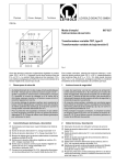
D Einbauanleitung Elektroanlage für Anhängevorrichtung F Instructions de montage Installation électrique pour dispositif dattelage GB EI Installation Instructions Electrical System for Towing Hitch Istruzioni di montaggio Impianto elettrico per il gancio di traino 305 171 391 101 - 34/01 Audi A6 Limousine 1 D Einbauanleitung Elektroanlage für Anhängevorrichtung 7/13-polig Westfalia Nr.: 305 171 300 107 / 113 Verwendungsbereich: Audi A6 Limousine ab 05/97 alle auch mit Check-Control und APS Allgemeine Hinweise: Vor Arbeitsbeginn bitte die Einbauanleitung durchlesen. Gebohrte Löcher müssen entgratet und anschließend mit Schutzlack gestrichen werden. Die Installation des Elektrosatzes darf nur bei abgeklemmter Batterie von Fachpersonal durchgeführt werden. Vor dem Bohren bitte prüfen, daß genügend Freiraum hinter der Verkleidung vorhanden ist. Achtung: Elektronisch gespeicherte Daten (Autoradio, Bordcomputer, etc.) können verloren gehen. Bei Anhängerbetrieb wird die Nebelschlußleuchte des Zugfahrzeugs durch das Steuergerät abgeschaltet. Bei älteren Anhängern ohne Nebelschlußleuchte ist bei Betrieb dieser E-Anlage eine Nebelschlußleuchte nachzurüsten. Der Ausfall einer Blinkleuchte, auch am Anhänger wird durch die Erhöhung der Blinkfrequenz angezeigt. Dadurch ist keine zusätzliche Blinkkontrolle notwendig. Ein Steckdosenadapter darf nur im Anhängerbetrieb genutzt werden. Nach dem Anhängerbetrieb ist dieser zu entfernen! Maßgebend für alle Rechtsfragen ist die deutschsprachige Ausgabe dieser Einbauanleitung. Änderungen vorbehalten! 2 D Verlegung Leitungsstrang, Montage Steuergerät 1. Minusklemme von der Batterie abklemmen. 2. Kofferraum-Bodenabdeckung, linke und rechte Seitenverkleidung, Bordwerkzeug und Wagenheber herausnehmen. Verkleidung vom Heckabschluß ausbauen. Links hinter dem Radkasten etwas zur Fahrzeugmitte im Bodenblech die Abdeckung der fahrzeugseitigen Durchführung entfernen. 3. Das mitgelieferte Steuergerät mit beiliegendem Klettband im Bereich hinter dem linken Radkasten befestigen. 4. Das Steckdosenende des Steckdosen-Leitungsstranges durch die fahrzeugseitige Durchführung nach außen zum Steckdosenhalteblech verlegen. Die beiliegende Durchführungstülle auf Leitungsstrang ziehen und in die Durchführung einsetzen. Steckdosendichtung aufziehen und die Steckdose nach dem Belegungsplan anklemmen. Innenteil mit dem Steckdosengehäuse zusammenstecken, Steckdosendichtung platzieren und mit den beigelegten Schrauben auf den Halter schrauben. Auf ordnungsgemäßen Sitz der Dichtungselemente achten. Den 12-poligen Stecker in das Anhänger-Steuergerät verrasten. 5. Den weißen 18-poligen Stecker des 2. Leitungsstranges in das Anhänger-Steuergerät verrasten und den Leitungsstrang mit den Farben grün-weiß, gelb, ... zur linken Heckleuchte verlegen, fahrzeugseitigen Heckleuchtenstecker abziehen und in den entsprechenden Gegenstecker des Leitungsstranges verrasten. Das verbleibende Steckergehäuse auf die Heckleuchte stecken. 6. Leitungsstrang mit den Farben grau-gelb, grau-rot, ... zur rechten Kofferraumseite verlegen, fahrzeugseitigen Heckleuchtenstecker abziehen und in den entsprechenden Gegenstecker des Leitungsstranges verrasten. Verbleibendes Gehäuse auf die Heckleuchte stecken. 7. Braun-weiße 2,5mm² Masseleitung mit der Ringöse an einen geeigneten fahrzeugseitigen Massepunkt (Loch oberhalb der linken Heckleuchte) mit geeigneter Schraube anschrauben. 8. Im fahrzeugseitigen Leitungsstrang zum Kofferraum verläuft eine grau-weiße Leitung mit der Funktion Nebelschlußleuchte. Diese Leitung an geeigneter Stelle hinter der linken Kofferraum-Verkleidung durchtrennen und beide Enden ca. 5mm abisolieren. An dem Leitungsende, daß vom Nebelschlußleuchtenschalter kommt, den beiliegenden Flachstecker ancrimpen und Isoliergehäuse aufschieben. An das Leitungsende zur Fahrzeug-Nebelschlußleuchte die beiliegende Flachsteckhülse ancrimpen und Isoliergehäuse aufschieben. Dann diese beiden Leitungen in die entsprechenden Gegengehäuse, Leitungen blau und grau der E-Anlage, verrasten. 9. Die 1,5mm² rot und 1,5mm² rot-schwarze Leitung vom Anhänger-Steuergerät entlang der linken Fahrzeugseite bis zum Fußraum Fahrerseite verlegen. Die Flachsteckhülse der roten Einzelleitung und die Flachsteckhülse einer beiliegenden Einzelleitung in den Sicherungshalter einrasten, Sicherungsclips einsetzen, die Sicherung (15A) in den Sicherungshalter einstecken und den Deckel auf den Sicherungshalter aufstecken. Gleiches mit der rot-schwarzen Leitung vollziehen. Die Ringösen der roten Leitungen an geeigneter Klemme 30 an die Anschlußleiste am Relaisträger anschrauben. 3 D 10. Die braun-weiße 0,35mm² Einzelleitung ist für Fahrzeuge mit Einparkhilfe (APS) vorgesehen. In diesem Fall wird diese Leitung am Steuergerät der Einparkhilfe (APS, Seitenwand hinten links) angeschlossen (siehe Bedienungsanleitung der Einparkhilfe/APS bzw. Fachwerkstatt aufsuchen). Bei Fahrzeugen ohne Einparkhilfe (APS) wird diese braun-weiße Einzelleitung nicht angeschlossen. Die verlegten Leitungen und den Sicherungshalter mit Kabelbindern befestigen. Ausgebaute Teile wieder einbauen, Minusklemme der Batterie wieder anschließen. Alle Funktionen mit einem geeigneten Prüfgerät (mit Belastungswiderständen) oder mit einem Anhänger prüfen! Belegung der 7-poligen Steckdose Stromkreis Leitung Kontakt Blinkleuchte links Nebelschlußleuchte Masse (Stromkreis 1-8) Blinkleuchte, rechts Schlußleuchte, rechts Bremsleuchte Schlußleuchte, links schwarz/weiß weiß braun/weiß schwarz/grün grau/rot schwarz/rot grau/schwarz 1/L 2/54g 3/31 4/R 5/58R 6/54 7/58L Belegung der 13-poligen Steckdose Stromkreis Leitung Kontakt Blinkleuchte links Nebelschlußleuchte Masse (Stromkreis 1-8) Blinkleuchte, rechts Schlußleuchte, rechts Bremsleuchte Schlußleuchte, links Rückfahrscheinwerfer Dauerplus Ladeleitung nicht zugeteilt nicht zugeteilt Masse (Stromkreis 9-12) schwarz/weiß weiß braun/weiß schwarz/grün grau/rot schwarz/rot grau/schwarz grün rot gelb --braun 1 2 3 4 5 6 7 8 9 10 11 12 13 Die nicht belegte 3-polige Buchse dient zur Adaption eines separaten Dauerplusleitungssatzes. Dieser kann, falls gewünscht, bei einem Westfalia-Händler unter der Teile Nr. 300 025 300 113 bezogen werden. Änderungen vorbehalten! 4 F Instructions de montage Installation électrique pour dispositif dattelage 7/13 bornes Référence Westfalia: 305 171 300 107 / 113 Domaine dutilisation: Limousine Audi A6 à partir de mai 97, tous les modèles également ceux avec système de contrôle électronique et détecteur d'obstacles Informations générales: Avant de commencer les travaux, veuillez lire les instructions de montage. Les trous venant dêtre percés doivent être ébarbés et protégés en y passant de la laque spéciale. Seul du personnel qualifié a le droit dinstaller le set électrique après avoir débranché la batterie. Veuillez contrôler avant de percer les trous sil y a bien suffisamment despace derrière lhabillage. Attention : les données électroniques mémorisées (autoradio, ordinateur de bord, etc.) peuvent disparaître. Lantibrouillard arrière de la voiture est éteint par le calculateur si une remorque/caravane est tractée. Sur des remorques plus anciennes dépourvues de feu antibrouillard arrière, il faut en monter un ultérieurement lors de la mise en service de cette installation électrique. La défaillance dun clignotant, de la remorque/caravane également, est signalée par une fréquence plus rapide. Un contrôle nest donc pas nécessaire. Un adaptateur pour prise de courant ne doit être utilisé que si une remorque/caravane est tractée. Le retirer après lavoir détachée! Lédition en allemand de ces instructions de montage est la seule valable en ce qui concerne les questions juridiques. Tous droits de modifications réservés! 5 F Pose du faisceau de câbles, montage de l'appareil de commande 1. Isoler la borne négative de la batterie. 2. Retirer le revêtement de sol du coffre, l'habillage latéral gauche et droit, l'outillage de bord et le cric. Retirer l'habillage de la tôle arrière. Retirer le cache de la conduite des câbles se trouvant dans la tôle du plancher, à gauche derrière le carter de roue, légèrement décalée vers le centre. 3. Fixer l'appareil de commande livré avec un morceau de bande velcro derrière le carter de roue gauche. 4. Faire passer l'extrémité avec la prise du faisceau de câbles à travers la conduite pour les câbles jusqu'à sa sortie vers la tôle de support de prise. Enfiler la gaine fournie sur le faisceau de câbles et l'insérer dans l'évidement du passage des câbles. Enfiler la garniture étanche de la prise et connecter la prise conformément au plan d'affectation. Assembler la partie intérieure avec le boîtier de la prise, mettre la garniture étanche en place, et la visser sur le support à l'aide des vis fournies. Veiller au logement correct des éléments d'étanchéité. Engager le connecteur à 12 pôles dans l'appareil de commande de la remorque. 5. Enfoncer la prise à 18 pôles de couleur blanche, faisant partie du deuxième faisceau, dans l'appareil de commande de la remorque et poser le faisceau aux couleurs vert/blanc, jaune, ...vers le feu arrière gauche, retirer la prise du feu arrière du véhicule et l'enfoncer dans la prise correspondante du faisceau de câbles. Poser le boîtier de prise restant sur le feu arrière. 6. Poser le faisceau de câbles aux couleurs gris-jaune, gris-rouge, ...vers le côté droit du coffre, retirer la prise du feu arrière du véhicule et l'enfoncer dans la prise correspondante du faisceau. Poser le boîtier de prise restant sur le feu arrière. 7. Visser à l'aide d'une vis appropriée le câble de la masse, fil marron-blanc de 2,5 mm² doté d'une cosse à illet, à un endroit convenable sur le véhicule pour établir la masse (trou audessus du feu arrière gauche). 8. Le faisceau de câbles du véhicule allant vers le coffre comprend un fil gris-blanc prévu pour faire fonctionner le feu antibrouillard arrière. Sectionner ce fil à un endroit adéquat, derrière l'habillage gauche du coffre, et en dénuder les deux extrémités sur environ 5mm. Sertir la fiche plate mâle fournie sur l'extrémité du fil en provenance du contacteur de feu antibrouillard arrière et enfiler le boîtier isolant. Sertir la fiche plate femelle fournie sur l'extrémité du fil allant vers le feu antibrouillard arrière du véhicule et enfiler le boîtier isolant. Ensuite, engager ces deux fils dans les logements complémentaires correspondants, fils bleu et gris de l'installation électrique. 9. Poser les fils rouge et rouge-noir de 1,5 mm² de l'appareil de commande de la remorque du côté gauche du véhicule jusqu'à l'espace avant, côté passager. Engager la fiche femelle plate du câble unifilaire rouge et la fiche femelle plate du câble unifilaire fourni dans le portefusibles, mettre les clips de sûreté en place, mettre le fusible (15A) dans le porte-fusibles et placer le couvercle sur le porte-fusibles. Procéder de même avec le câble rouge-noir. Visser les cosses à illet des fils rouges sur la borne 30 du bornier, au niveau du porte relais. 6 F 10. Le câble unifilaire marron-blanc de 0,35 mm² est prévu pour des véhicules équipés d'un détecteur d'obstacles. Dans ce cas là, ce câble est à raccorder à l'appareil de commande du détecteur d'obstacles (détecteur d'obstacles, paroi latérale gauche arrière). Voir le manuel d'utilisation du détecteur d'obstacles ou consulter un atelier spécialisé. Pour les véhicules sans détecteur d'obstacles, ce câble unifilaire marron-blanc n'est pas raccordé. Fixer les câbles posés et le porte-fusibles à l'aide de colliers de frettage. Remonter les pièces démontées, connecter à nouveau la borne négative de la batterie. Vérifier toutes les fonctions avec l'appareil de contrôle approprié (avec des résistances de charge) ou avec une remorque ! Disposition de la prise à 7 pôles circuit électrique câble contact clignotant gauche feu arrière antibrouillard masse (circuit électrique 1-8) clignotant droit feu arrière droit feu stop feu arrière gauche noir/blanc blanc marron/blanc noir/vert gris/rouge noir/rouge gris/noir 1/L 2/54g 3/31 4/R 5/58R 6/54 7/58L Disposition de la prise à 13 pôles circuit électrique câble contact clignotant gauche feu arrière antibrouillard masse (circuit électrique 1-8) clignotant droit feu arrière droit feu stop feu arrière gauche phares de recul borne positive constante câble de charge sans fonction sans fonction masse (circuit électrique 9-12) noir/blanc blanc marron/blanc noir/vert gris/rouge noir/rouge gris/noir vert rouge jaune --marron 1 2 3 4 5 6 7 8 9 10 11 12 13 La douille à 3 broches non occupée sert à l'adaptation d'un faisceau de câbles séparé à courant positif permanent. Celui-ci est disponible sur demande chez un concessionnaire Westfalia sous le n° d'article 300 025 300 113 . Tous droits de modifications réservés! 7 GB Installation Instructions Electrical System for Towing Hitch 7/13-pin Westfalia Order No.: 305 171 300 107 / 113 Area of Application: Audi A6 Limousine from 05/97, all also with Check-Control and APS General Information: Before starting work, please read the installation instructions. The holes drilled must be deburred and then coated with anti-corrosion paint. The electrical set may only be installed by specially-trained personnel with the battery disconnected. Please make sure before drilling that there is sufficient clearance behind the trim. Important: Any electronically stored data (car radio, onboard computer etc.) may be lost. During trailer towing the rear fog light of the pulling vehicle is switched off by the control unit. Install a rear fog lamp on older trailers if they do not already have one before operating this electrical equipment with them. The failure of a turn signal, including on the trailer, is indicated by an increase in the flashing frequency. As a result, no additional flashing check is required. An electrical socket adapter may only be used during trailer towing, and must be removed after trailer towing is completed! The German version of these installation instructions shall be applicable in event of any legal questions. Subject to modification! 8 GB Moving wire lane, installation of control unit 1. Remove negative terminal from the battery. 2. Remove luggage compartment floor cover, left and right side coverings, tool kit and vehicle jack. Remove tail plate covering. Remove the covering of the vehicle's lead-through located in the floor panel slightly towards the vehicles centre on the left behind the wheel case. 3. Attach the supplied control unit in the area behind the left wheel case using the enclosed Velcro tape. 4. Lay the socket end of the wire lane through the vehicle's leadthrough out to the power socket retaining plate. Pull the enclosed leadthrough bushing onto the wire lane and insert into the leadthrough. Fit on the socket sealing and connect the socket according to the wiring plan. Fit together the inner part with the socket housing, put the socket sealing in place and screw onto the holder with the enclosed screws. Make sure the seals sits properly. Attach the 12-pin plug to the trailer control unit. 5. Attach the white 18-pin plug of the 2nd wire lane to the trailer control unit and lay the wire lane coloured green-white, yellow, ... to the left tail light, pull out the tail light plug and stick it into the relevant counter plug of the wire lane. Place the remaining plug shell on the rear light. 6. Lay the wire lane coloured grey-yellow, grey-red, ... to the right of the boot, pull out the tail light plug and stick it into the relevant counter plug of the wire lane. Place the remaining shell on the rear light. 7. Attach the brown-white 2.5mm² earth wire with the ring eyelet to a suitable earthing point on the vehicle (e.g. hole above left rear light) with a suitable screw. 8. A grey-white wire for the rear fog lamp runs through the vehicle's wire lane to the boot. Cut this wire at a suitable location behind the left boot covering and strip approx. 5mm from both ends. Crimp the enclosed flat plug to the wire coming from the rear fog lamp switch and pull on insulation housing. Crimp the enclosed flat plug to the wire going to the rear fog lamp and pull on insulation housing. Then attach these two wires into the respective opposite housings, blue and grey lines of the electrical equipment. 9. Lay the 1.5mm² red and red-black wires from the trailer control unit along the vehicle's left side into the driver's leg room. Insert the flat plug receptacle of the red single wire and the flat plug receptacle of an enclosed single wire into the fuse holder, attach the fuse clips, insert the fuse (15A) into the fuse holder and place the cover onto the fuse holder. Do the same with the red-black wire. Screw the ring eyelets of the red wires to the appropriate terminal 30 of the relay lane connecting block. 9 GB 10. The 0.35mm² brown-white single wire is used for vehicles with parking aid (APS). In this case this wire is attached to the parking aid's control unit (APS, rear left side panel). (Refer to operating manual of the parking aid/APS or contact a garage.) This single brown-white wire is not used in vehicles that don't have parking aid (APS). Secure the placed wires and fuse holder with cable binders. Re-install removed parts, re-connect the battery's negative terminal. Check all functions with a suitable testing instrument (with load resistance) or with a towed vehicle! Allocation of the 7-pin socket Circuit Wire Contact Left turn signal lamp Rear fog lamp Earth (circuit 1-8) Right turn signal lamp Right tail light Stop light Left tail light black/white white brown/white black/green gray/red black/red gray/black 1/L 2/54g 3/31 4/R 5/58R 6/54 7/58L Allocation of the 13-pin socket Circuit Wire Contact Left turn signal lamp Rear fog lamp Earth (circuit 1-8) Right turn signal lamp Right tail light Stop light Left tail light Back light Continuous positive Charge line Not assigned Not assigned Earth (circuit 9-12) black/white white brown/white black/green gray/red black/red gray/black green red yellow --brown 1 2 3 4 5 6 7 8 9 10 11 12 13 The unassigned 3-pin socket is used to adapt a separate continuous positive wire set. If needed, this can be purchased at a Westfalia dealer under the part number 300 025 300 113 . Subject to modification! 10 I Istruzioni di montaggio Impianto elettrico per il gancio di traino 7/13 poli N. dordinazione Westfalia: 305 171 300 107 / 113 Campo dimpiego: Audi A6 Limousine, a partire da maggio 97 tutti i modelli anche quelli con sistema di controllo elettronico e dispositivo ausiliario parcheggio (APS) Avvertenze generali: Prima di iniziare i lavori leggere le istruzioni di montaggio. I fori eseguiti devono essere sbavati e successivamente trattati con vernice protettiva. Il kit elettrico deve essere installato solo da tecnici specializzati dopo aver scollegato la batteria. Prima di effettuare i fori controllare che dietro il rivestimento ci sia sufficiente spazio libero. Attenzione: Si possono perdere i dati memorizzati elettronicamente (autoradio, computer di bordo ecc.). In caso di funzionamento con rimorchio il retronebbia della motrice viene disinserito dalla centralina di comando. L'uso di questo impianto elettrico richiede l'installazione di una luce antinebbia posteriore per i vecchi rimorchi che non ne sono provvisti. Il guasto di un lampeggiatore, anche del rimorchio, viene segnalato con laumento della frequenza di lampeggio. Pertanto non è necessario un ulteriore controllo lampeggiatori. Ladattatore presa deve essere usato solo durante il funzionamento con rimorchio e deve essere eliminato quando viene sganciato il rimorchio! Per qualsiasi controversia è valida ledizione tedesca delle istruzioni di montaggio. Ci riserviamo modifiche! 11 I Posa del fascio di conduttori e montaggio della centralina di comando 1. Staccare il morsetto negativo dalla batteria. 2. Rimuovere il rivestimento del fondale del bagagliaio, il rivestimento laterale destro e sinistro, gli attrezzi di bordo e il dispositivo di sollevamento. Smontare il rivestimento della lamiera posteriore. Sul lato sinistro, dietro il parafango circa a metà del veicolo sulla lamiera di fondo, rimuovere la copertura del foro di guida per cavi del veicolo. 3. Fissare con il velcro la centralina di comando, compresa nella fornitura, dietro il parafango della ruota sinistra. 4. Facendola passare per l'apposito foro nel veicolo, portare l'estremità del fascio di cavi con la presa verso l'esterno, fino al supporto portaprese. Disporre l'isolatore passante in dotazione sul fascio di cavi e inserirlo nel foro. Disporre sulla presa l'apposita guarnizione e collegare la presa secondo lo schema di assegnazione. Montare insieme la parte interna e la scatola della presa, sistemare in sede la guarnizione della presa e avvitarla al supporto con le viti in dotazione. Assicurarsi che le guarnizioni siano correttamente in sede. Ricollegare il connettore a 12 poli nella centralina di comando. 5. Collegare il connettore a 18 poli del secondo fascio di cavi nella centralina di comando e portare il fascio di cavi con i colori verde-bianco, giallo, ... verso il fanale posteriore sinistro, staccare la spina del fanale posteriore del veicolo e inserirla nel connettore di accoppiamento corrispondente del fascio di cavi. Disporre la scatola della spina rimanente sul fanale posteriore. 6. Portare il fascio di cavi con i colori grigio-giallo, grigio-rosso, ... verso il lato destro del bagagliaio, staccare la spina del fanale posteriore del veicolo e inserirla nel connettore di accoppiamento corrispondente del fascio di cavi. Disporre la scatola della spina rimanente sul fanale posteriore. 7. Fissare per mezzo di una vite appropriata il cavo di massa marrone-bianco di 2,5mm² con l'occhiello ad un punto di massa adatto del veicolo nell'area posteriore (foro situato sopra il fanale posteriore sinistro). 8. Il fascio di cavi del veicolo verso il bagagliaio comprende un cavo grigio-bianco per il funzionamento della luce antinebbia posteriore. Dividere questo cavo in un luogo adeguato, dietro il rivestimento sinistro del bagagliaio e denudare entrambe le estremità per circa 5mm. Inserire le spine piatte e infilare l'involucro isolante all'estremità del cavo proveniente dall'interruttore della luce antinebbia posteriore. Inserire le spine piatte e infilare l'involucro isolante all'estremità del cavo che va all'interruttore della luce antinebbia posteriore. Inserire quindi entrambi i cavi nelle scatole complementari corrispondenti, cavo blu e grigio dell'impianto elettrico. 9. Portare il cavo da 1,5 mm² rosso e da 1,5 mm² rosso-nero dalla centralina di comando del rimorchio del lato sinistro del veicolo fino allo spazio davanti ai piedi del guidatore. Innestare la spina piatta femmina del cavo singolo rosso e la spina piatta femmina di un cavo in dotazione nel portafusibili, montare i clip di sicurezza, inserire il fusibile (15 A) nel portafusibili e coprire quest'ultimo con il relativo coperchio. Eseguire la stessa procedura con il cavo rosso-nero. Avvitare gli occhielli dei cavi rossi all'apposito morsetto 30 della morsetteria del portarelè. 12 I 10. Il conduttore singolo bianco-marrone da 0,35mm² è previsto per veicoli con dispositivo ausiliario per parcheggio (APS). In questo caso il conduttore singolo viene collegato alla centralina di comando del dispositivo ausiliario per parcheggio (parete laterale posteriore sinistra; vedere istruzioni per l'uso del dispositivo ausiliario APS, oppure rivolgersi ad un'officina specializzata). Nei veicoli sprovvisti di questo dispositivo ausiliario (APS), il conduttore singolo non deve essere collegato. Fissare i cavi posati e il portafusibili mediante fascette. Rimontare i pezzi smontati e ricollegare il morsetto negativo della batteria. Controllare tutte le funzioni con un apparecchio di controllo adatto (con resistenza di carico) o con un rimorchio! Disposizione della presa a 7 poli Circuito elettrico Conduttore Contatto Lampeggiatore sinistro Luce antinebbia posteriore Massa (circuito 1-8) Lampeggiatore destro Luce posizione posteriore destra Luce di arresto Luce posizione posteriore sinistra nero/bianco bianco marrone/bianco nero/verde grigio/rosso nero/rosso grigio/nero 1/L 2/54g 3/31 4/R 5/58R 6/54 7/58L Disposizione della presa a 13 poli Circuito elettrico Conduttore Contatto Lampeggiatore sinistro Luce antinebbia posteriore Massa (circuito 1-8) Lampeggiatore destro Luce posizione posteriore destra Luce di arresto Luce posizione posteriore sinistra Proiettore di retromarcia Positivo continuo Linea di carica non assegnato non assegnato Massa (circuito 9-12) nero/bianco bianco marrone/bianco nero/verde grigio/rosso nero/rosso grigio/nero verde rosso giallo --marrone 1 2 3 4 5 6 7 8 9 10 11 12 13 La presa a 3 poli non assegnata può essere utilizzata per l'adattamento di un fascio supplementare di cavi positivi continui. Tale fascio supplementare può essere richiesto presso un rivenditore Westfalia indicando il codice di ordinazione 300 025 300 113. Ci riserviamo modifiche! 13