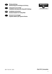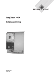
1
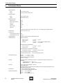
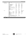
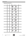
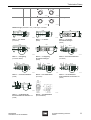
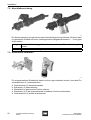
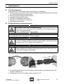
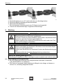
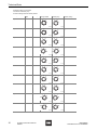
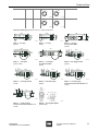
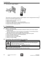
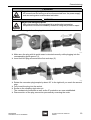
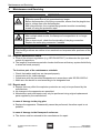
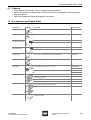
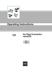
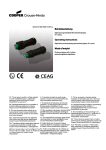
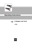
Betriebsanleitung/Operating Instructions
Ex Steckverbindung
miniCLIX
Ex Plug Connector
miniCLIX
> 8591/2
Betriebsanleitung
Ex Steckverbindung
miniCLIX
> 8591/2
Inhaltsverzeichnis
1
Inhaltsverzeichnis
1
2
2.1
2.2
2.3
3
3.1
3.2
3.3
3.4
4
5
6
7
7.1
7.2
7.3
7.4
7.5
7.6
7.7
7.8
7.9
8
8.1
8.2
9
9.1
9.2
9.3
10
11
12
2
Inhaltsverzeichnis ..................................................................................................2
Allgemeine Angaben .............................................................................................3
Hersteller ...............................................................................................................3
Angaben zur Betriebsanleitung .............................................................................3
Verwendete Symbole ............................................................................................3
Allgemeine Sicherheitshinweise ............................................................................4
Sicherheitshinweise für Montage- und Bedienpersonal ........................................4
Warnhinweise ........................................................................................................5
Besondere Bedingungen .......................................................................................5
Normenkonformität ................................................................................................6
Vorgesehener Einsatzbereich ...............................................................................7
Technische Daten .................................................................................................8
Transport, Lagerung und Entsorgung .................................................................12
Installation ...........................................................................................................12
Getestete Kabeltypen ..........................................................................................13
Crimpanschluss ...................................................................................................14
Stecker/Kupplung (Ex-e) - Kunsttoff/Metall mit Crimpanschluss .........................15
Gerätestecker/Flanschsteckdose (Ex-e) - Kunststoff mit Crimpanschluss ..........17
Armierte Leitung Stecker/Kupplung (Ex-e) - Metall .............................................18
Stecker/Kupplung (Ex-e) - Kunststoff/Metall mit Käfigzugfederanschluss ..........19
Direktanschluss über Einzeladern bei Gerätestecker/
Flanschsteckdose in Metallausführungen ...........................................................21
Abschließvorrichtung ...........................................................................................22
Winkelstück verdrehen ........................................................................................22
Inbetriebnahme ...................................................................................................23
Vor Inbetriebnahme .............................................................................................23
Steckverbindung verbinden/trennen ....................................................................23
Wartung ...............................................................................................................24
Regelmäßige Wartungsarbeiten ..........................................................................24
Reparaturarbeiten ...............................................................................................25
Reinigung ............................................................................................................25
Zubehör und Ersatzteile .....................................................................................25
EG-Baumusterprüfbescheinigung (1. Seite) ........................................................27
EG-Konformitätserklärung ...................................................................................28
Ex Steckverbindung miniCLIX
8591/2
8591609300
S-BA-8591/2-01-de-04/09/2009
Allgemeine Angaben
2
Allgemeine Angaben
2.1 Hersteller
R. STAHL Schaltgeräte GmbH
Am Bahnhof 30
D-74638 Waldenburg
Telefon:
Telefax:
Internet:
+49 7942 943-0
+49 7942 943-4333
www.miniclix.info
www.stahl.de
2.2 Angaben zur Betriebsanleitung
ID-NR.:
8591609300
Publikationsnummer:
S-BA-8591/2-01-de-04/09/2009
Technische Änderungen vorbehalten.
2.3 Verwendete Symbole
X
Z
X
)
Handlungsaufforderung:
Beschreibt durch den Anwender auszuführende Tätigkeiten.
Reaktionszeichen:
Beschreibt Resultate bzw. Reaktionen auf Tätigkeiten.
Aufzählungszeichen
Hinweiszeichen:
Beschreibt Hinweise und Empfehlungen.
Warnzeichen:
Gefahr durch spannungsführende Teile
Warnzeichen:
Gefahr durch explosionsfähige Atmosphäre!
8591609300
S-BA-8591/2-01-de-04/09/2009
Ex Steckverbindung miniCLIX
8591/2
3
Allgemeine Sicherheitshinweise
3
Allgemeine Sicherheitshinweise
3.1 Sicherheitshinweise für Montage- und Bedienpersonal
Die Betriebsanleitung enthält grundlegende Sicherheitshinweise, die bei Aufstellung, Betrieb und Wartung zu beachten sind. Nichtbeachtung hat eine Gefährdung für Personen,
Anlage und Umwelt zur Folge.
Die Steckverbindungen 8591/2 sind zum Einsatz in explosionsgefährdeten Bereichen
der Zonen 1 und 2 gemäß EN-Normen sowie im Industriebereich geeignet.
WARNUNG
Gefahr durch unbefugte Arbeiten am Gerät!
Z Verletzungen und Sachschäden drohen.
X Montage, Installation, Inbetriebnahme, Betrieb und Wartung dürfen ausschließlich
von dazu befugtem und entsprechend geschultem Personal durchgeführt werden.
Vor Montage/Inbetriebnahme:
X Betriebsanleitung lesen.
X Montage- und Betriebspersonal ausreichend schulen.
X Sicherstellen, dass der Inhalt der Betriebsanleitung vom zuständigen Personal voll
verstanden wird.
X Es gelten die nationalen Montage- und Errichtungsvorschriften
(z.B. IEC/EN 60079-14).
Bei Betrieb der Geräte:
X Gerät darf unter Last nur bis max. 250 V AC und max. 10 A Bemessungsstrom gesteckt und getrennt werden. Bei höheren Bemessungswerten ist das System vorher
spannungs- und stromfrei zu schalten.
X Betriebsanleitung am Einsatzort verfügbar halten.
X Sicherheitshinweise beachten.
X Nationale Sicherheits- und Unfallverhütungsvorschriften beachten.
X Wartungsarbeiten bzw. Reparaturen, die nicht in der Betriebsanleitung beschrieben
sind, dürfen nicht ohne vorherige Abstimmung mit dem Hersteller durchgeführt werden.
X Beschädigungen können den Explosionsschutz aufheben.
X Umbauten und Veränderungen am Gerät sind generell nicht zulässig.
X Gerät nur in unbeschädigtem, trockenem und sauberem Zustand einbauen und betreiben.
X Gerät nur mit den zugehörigen unbeschädigten Steckern und Kupplungen betreiben.
X Die Steckverbindungen dürfen auch für eigensichere Stromkreise gemäß Ex ia/ib IIC
T6 verwendet werden. Bei der Verwendung für eigensichere Stromkreise muss eine
entsprechende Kennzeichnung erfolgen.
X Eigensichere und nicht-eigensichere Stromkreise dürfen nicht gemeinsam in einer
Steckverbindung geführt werden.
X Sicherstellen, dass Stecker/Gerätestecker bei getrennter Steckverbindung spannungsfrei ist.
X Spannungsführende Kupplungen/Flanschsteckdosen sofort nach dem Trennen mit
der Schutzkappe verschließen. Dabei korrekten Verschluss sicherstellen, da ansonsten die Mindestschutzart und der Explosionsschutz nicht mehr gewährleistet sind.
X Nicht benutzte Komponenten mit der Schutzkappe verschlossen lagern.
4
Ex Steckverbindung miniCLIX
8591/2
8591609300
S-BA-8591/2-01-de-04/09/2009
Allgemeine Sicherheitshinweise
Bei Unklarheiten:
X Mit Hersteller Kontakt aufnehmen.
3.2 Warnhinweise
Warnhinweise sind in dieser Betriebsanleitung nach folgendem Schema gegliedert:
WARNUNG
Art und Quelle der Gefahr!
Z Mögliche Folgen.
X Maßnahmen zur Vermeidung der Gefahr.
Sie sind immer mit dem Signalwort „WARNUNG“ und teilweise mit einem
gefahrenspezifischen Symbol gekennzeichnet.
3.3 Besondere Bedingungen
WARNUNG
Gefahr durch spannungsführende Teile!
Z Schwerste Verletzungen drohen.
X Alle Anschlüsse und Verdrahtungen spannungsfrei schalten.
X Anschlüsse gegen unbefugtes Schalten sichern.
Temperaturklasse und Zündschutzart
X Die auf dem Gerät angegebene Temperaturklasse und Zündschutzart einhalten.
Anforderungen an die Anschlussleitung:
X Anschlussleitung der Steckverbindung fest und vorschriftsmäßig verlegen.
X Sicherstellen, dass sie vor mechanischer Beschädigung geschützt ist.
X Anschlussleitung so wählen, dass sie den thermischen und mechanischen Anforderungen im Einsatzbereich genügt.
X Anschlussleitung darf nicht unter Zug stehen.
Bei Anschluss in explosionsgefährdeten Bereichen:
X Anschlussraum verwenden, der den Anforderungen einer anerkannten Zündschutzart
nach IEC/EN 60079-0, Abschnitt 1.2 entspricht.
Metallausführung der Flanschsteckdose, des Gerätesteckers und des Winkelstücks:
X Einbau zulässig in Wandungen von Gehäusen der Zündschutzart Druckfeste Kapselung „d“ oder Erhöhte Sicherheit „e“.
8591609300
S-BA-8591/2-01-de-04/09/2009
Ex Steckverbindung miniCLIX
8591/2
5
Allgemeine Sicherheitshinweise
Kunststoffausführung der Flanschsteckdose, des Gerätesteckers und des Winkelstücks:
X Einbau zulässig in Wandungen von Gehäusen der Zündschutzart oder Erhöhte Sicherheit „e“.
X Kunststoffausführung der Steckverbindung bei Temperaturen unter -20°C mechanisch geschützt errichten.
X Kunststoffwinkelstück bei Temperaturen unter -20°C nicht einsetzen.
Bei Verwendung von Anschlussräumen in der Zündschutzart Erhöhte Sicherheit
„e“ nach IEC/EN 60079-7:
X Luft- und Kriechstrecken nach Abschnitt 4.3, Abschnitt 4.4 und Tabelle 1 einhalten.
Potentialausgleich:
X Potentialausgleich bzw. Erdung durch den Anbau der Metallausführungen der
Flanschsteckdose, des Gerätesteckers und/oder des Winkelstücks an die Gesamtanlage gewährleisten.
3.4 Normenkonformität
Die Steckverbinder wurden gemäß dem Stand der Technik und gemäß EN 29001 (ISO
9001) entwickelt, gefertigt und geprüft.
Sie entsprechen unter anderem folgenden Bestimmungen und Normen:
X
X
X
X
X
X
X
6
IEC/EN 60079-0
IEC/EN 60079-1
IEC/EN 60079-7
IEC/EN 60079-11
IEC/EN 60079-14
94/9 EG
89/336/EWG „Elektromagnetische Verträglichkeit“
Ex Steckverbindung miniCLIX
8591/2
8591609300
S-BA-8591/2-01-de-04/09/2009
Vorgesehener Einsatzbereich
4
Vorgesehener Einsatzbereich
Die Steckverbindungen 8591/2 sind zum Einsatz in explosionsgefährdeten Bereichen
der Zonen 1 und 2 gemäß EN-Normen sowie im Industriebereich geeignet.
Umgebungsbedingungen
Die eingesetzten Gehäusematerialien, einschließlich der außenliegenden Metallteile, bestehen aus hochwertigen Werkstoffen, die einen anwendungsgerechten Korrosionsschutz und Chemikalienresistenz in Industrieatmosphäre gewährleisten:
X schlagfestes Polyamid
X Messing, vernickelt
X Edelstahl AISI 316L
Verwendung
Die Steckverbindungen 8591/2 dienen z.B.
X zur Signal- und Datenleitung,
X zur Stromversorgung von standortvariablen Vor-Ort-Steuerungen,
X zur Stromversorgung von elektrischen Anlagen, sowie von beweglichen Maschinen
und Antrieben
in explosionsgefährdeten Bereichen.
Sie werden zum Schnellanschluss von explosionsgeschützten elektrischen Betriebsmitteln im Ex- und Industriebereich verwendet.
8591609300
S-BA-8591/2-01-de-04/09/2009
Ex Steckverbindung miniCLIX
8591/2
7
Technische Daten
5
Technische Daten
Explosionsschutz
ATEX
E II 2 G Ex de IIC T6
IECEx
Ex de IIC T6 oder Ex ia/ib IIC T6
Bescheinigungen
ATEX
PTB 07 ATEX 1028 X
IECEx
IECEx BKI 07.0001X
Bemessungswerte
Spannung AC
400 V
Spannung AC (IECEx)
250 V
Strom AC
16 A*
Frequenz
400 Hz
Spannung DC
60 V
Strom DC
10 A
* Stecken und ziehen unter Last bis max. 250 V / 10 A zulässig (gem. IEC/EN 60079-0)
Schaltleistung
230 V / 400 V max. 10 A
Vorsicherung
ohne thermischen Schutz
16 A
mit thermischem Schutz
20 A gL
Gehäusematerial
Messing vernickelt; Polyamid; Edelstahl AISI 316L
Anschlusstechnik
Kupplung / Stecker
Crimp 1,5 mm2 *)
Crimp 2,5 mm2 *)
Federzug
0,75 mm2 ... 1,5 mm2
2,5 mm2
0,34 mm2 ... 1 mm2 (flexibel mit Aderendhülse)
0,34 mm2 ... 1 mm2 (starr)
Flanschsteckdose / Gerätestecker
Crimp 1,5 mm2 *)
Crimp 2,5 mm2 *)
0,75 mm2 ... 1,5 mm2
2,5 mm2
Flanschsteckdose / Gerätestecker aus Metall
mit Leitung (ca. 30 cm)
*)
Leitungseinführungen
0,75 mm2; 1,5 mm2; 2,5 mm2
nur mit spezial Crimpzange, siehe Zubehör;
alternativ: löten 0,34 mm2 ... 1 mm2 (mit Schrumpfschlauch)
8591/2..-..-...1
8591/2..-..-...2
d 7 mm ... 11 mm
d 11 mm ... 15 mm
Ausführungen für armierte Leitungen
d 16 mm ... 26 mm
Montage
Flanschsteckdose / Gerätestecker einfach in vorhandene Öffnungen einschrauben und
verdrahten
- Kunststoffausführung:
- Metallausführung:
8
M 25 x 1,5
M 25 x 1,5 oder 3/4“ NPT
Schutzart
IP 66 / IP 68 (2 m Wassersäule, 1 Stunde)
nach IEC/EN 60529
(bei geschlossenen und gesicherten Schutzkappen sowie ordnungsgemäß gesteckten und
gesicherten Komponenten)
Schutzklasse
I - wird von Metall-Ausführungen erfüllt
II - wird von Kunststoff-Ausführungen erfüllt
Umgebungstemperatur
- 20 °C ... + 40 °C (Kunststoff)
- 55 °C ... + 40 °C (Metall)
- 55 °C ... + 75 °C (Metall max. 1 A)
Ex Steckverbindung miniCLIX
8591/2
8591609300
S-BA-8591/2-01-de-04/09/2009
Technische Daten
Lagertemperatur
- 55 °C ... + 80 °C
Anzugsdrehmoment
Kunststoff
Metall (Ex e)
Metall (Ex d)
2,5 Nm
2,5 Nm
2,5 Nm
2,5 Nm
2,5 Nm
2,5 Nm
3,5 Nm
3,5 Nm
3,5 Nm
Einschraubgewinde (M 25)
Winkelstück
Flanschsteckdose
Gerätestecker
Überwurfmutter
2,5 Nm
2,5 Nm
2,5 Nm
Schutzkappe
2,5 Nm
2,5 Nm
2,5 Nm
Druckschraube mit Zugentlastung
4,0 Nm
4,0 Nm
4,0 Nm
äußere Druckschraube für armierte
Leitungen
2,5 Nm
2,5 Nm
2,5 Nm
innere Druckschraube für armierte
Leitungen
2,5 Nm
2,5 Nm
2,5 Nm
Arretierungsschrauben
1,0 Nm
1,0 Nm
--
Kunststoff
Metall
Metall - armierte
Ausführung
ca. 97g
ca. 92 g
ca. 64 g
ca. 75 g
-ca. 40 g
ca. 205 g
ca. 244 g
ca. 210 g
ca. 260 g
-ca. 191 g
ca. 420 g
ca. 420 g
--ca 303 g
--
ca. 10 g
ca. 13 g
ca. 44 g
ca. 80 g
Gewicht
Kupplung 1)
Stecker
Flanschsteckdose 1)
Gerätestecker 1)
Gerätestecker > 2 l1)
Winkelstück
8591/.3.-..-....
8591/.7.-..-....
8591/.8.-..-....
8591/.9.-..-....
8591/11.-..-....
Schutzkappen:
für Stecker / Gerätestecker
für Kupplung / Flanschsteckdose
1)
)
Gewicht inklusive Kunststoffschutzkappe
weitere technische Daten zur Projektierung: siehe Datenblatt
8591609300
S-BA-8591/2-01-de-04/09/2009
Ex Steckverbindung miniCLIX
8591/2
9
Technische Daten
Empfohlene Codierung der Steckverbindung
Führungsnase/Nut nach unten drehen (6 h)
Alle weiteren Codierungen resultieren aus dieser Lage
Spannung
Polzahl
Codierung
Sonderzeit
7P
1h
Kupplung /
Flanschsteckdose
6
Stecker /
Gerätestecker
7
1
5
4
1
2
3
ohne
6
7
5
2
4
3
05005E00
Sonderzeit
7P
2h
6
5
4
3
05056E00
grün
6
7
7
1
1
2
5
4
3
2
05014E00
Sonderzeit
7P
3h
5
4
7
1
2
ohne
5
6
7
3
05057E00
6
4
1
3
2
05027E00
110 V ... 130 V AC 6 P + ¿
4h
5
4
5
6
PE
2
05058E00
6
3
6P+¿
3
PE
1
5h
2
1
4
3
grün / rot
4
5
6
3
6
PE
1
05061E00
5
2
2
PE
1
05033E00
230 V ... 250 V AC 6 P + ¿
6h
3
05110E00
4
5
5
1
PE
6
6
rot
3
4
2
2
1
PE
05035E00
Sonderzeit
6P+¿
7h
3
2
05113E00
4
ohne
3
4
5
1
2
5
1
PE 6
6 PE
05043E00
24 V DC
7P
8h
2
05116E00
3
4
1
4
5
6
grau
2
3
1
7
5
7
6
05045E00
Sonderzeit
6P+¿
9h
2
1
05121E00
3
3
4
4
PE
6
2
6P+¿
10 h
PE
6
1
PE
5
5
6
5
2
Ex Steckverbindung miniCLIX
8591/2
1
3
4
4
05052E00
10
05122E00
2
3
ohne
1
05050E00
400 V AC
gelb
4
05028E00
Sonderzeit
Empfohlener
Farbring-Code
5
blau
PE
6
05123E00
8591609300
S-BA-8591/2-01-de-04/09/2009
Technische Daten
6P+¿
Sonderzeit
11 h
1
PE
6
5
4
2
2
3
3
1
6
5
4
05053E00
6P+¿
24 V AC
12 h
6
PE
4
05125E00
1
1
2
5
ohne
PE
PE
2
3
ohne Ring
6
5
3
4
05055E00
05126E00
Maßzeichnungen (alle Maße in mm) - Änderungen vorbehalten
~105
~105
05130E00
Ø36
M32
05132E00
~61,5
SW32
M25
SW32
M25
9
Ø36
05135E00
8591/.8.-..-0.01 Flanschsteckdose
(Kunststoff)
10
~61,5
Ø36
Ø36
SW32
M20x1,5
8591/.8.-..-..01 Flanschsteckdose
(Metall)
05134E00
8591/.9.-..-0.01 Gerätestecker
(Kunststoff)
05137E00
8591/.9.-..-..01 Gerätestecker
für Ex d Gehäuse mit Volumen < 2 l
(Metall)
80
Ø36
SW32
M25
~60,5
05128E00
8591/.3.-..-..01 Kupplung
für armierte Leitungen
(Metall)
05133E00
10
9
Ø36
Ø36
SW41
135
~60,5
05129E00
8591/.7.-..-..01 Stecker
für armierte Leitungen
(Metall)
Ø36
~105
8591/.3.-..-..0. Kupplung
(Kunststoff, Metall)
M32
05131E00
8591/.7.-..-..0. Stecker
(Metall)
SW32
M25
8591/.7.-..-0.0. Stecker
(Kunststoff)
10
SW41
Ø36
Ø36
143
05136E00
05127E00
8591/.6.-..-..01 Gerätestecker
für Ex d Gehäuse mit Volumen > 2 l
(Metall)
8591609300
S-BA-8591/2-01-de-04/09/2009
8591/11.-..-0.01 Winkelstück
(Kunststoff/Metall)
Ex Steckverbindung miniCLIX
8591/2
11
Transport, Lagerung und Entsorgung
6
Transport, Lagerung und Entsorgung
Transport
X Erschütterungsfrei in Originalkarton, nicht stürzen, vorsichtig handhaben.
Lagerung
X Trocken in Originalverpackung lagern.
X Zulässige Lagertemperatur in Originalverpackung: - 55 °C ... + 80 °C
Entsorgung
X Umweltgerechte Entsorgung aller Bauteile gemäß den gesetzlichen Bestimmungen
sicherstellen.
7
Installation
WARNUNG
Gefahr durch spannungsführende Teile!
Z Schwerste Verletzungen drohen.
X Alle Anschlüsse und Verdrahtungen spannungsfrei schalten.
X Anschlüsse gegen unbefugtes Schalten sichern.
)
)
)
)
WARNUNG
Nicht korrekt montierte Komponenten!
Z Bei nicht korrekt montierten Komponenten ist der Explosionsschutz nicht
mehr gewährleistet.
X Montage strikt nach Anleitung und unter Berücksichtigung der nationalen
Sicherheits- und Unfallverhütungsvorschriften (z.B. IEC/EN 60079-14)
durchführen.
Die Fa. R. STAHL liefert die miniCLIX Steckverbindungen auf Wunsch mit
vorkonfektionierten Leitungen aus. Bitte wenden Sie sich hierfür an Ihre zuständige Vertriebsniederlassung.
Übermäßiges Anziehen der Druckschraube kann die Zugentlastungs-/Dichtwirkung beeinträchtigen.
Gerätestecker und Flanschsteckdosen bevorzugt mit der Stecköffnung nach
unten einbauen.
Um eine einwandfreie Funktion des Steckers zu gewährleisten, auch nicht
belegte Stifte bestücken.
Vor der Installation:
X Alle Anschlüsse und Verdrahtungen spannungsfrei schalten und gegen unbefugtes
Schalten sichern.
X Bohrungen und Einschraubgewinde auf Unversehrtheit und Sauberkeit prüfen.
X Übereinstimmung von Gewinde und Gewindebohrungen sicherstellen.
X Korrekte Lage und Unversehrtheit des Dichtrings prüfen.
12
Ex Steckverbindung miniCLIX
8591/2
8591609300
S-BA-8591/2-01-de-04/09/2009
Installation
Vor Einbau von Flanschsteckdose, Gerätestecker und Winkelstücke in druckfeste
Gehäuse:
X Alle Anschlüsse und Verdrahtungen spannungsfrei schalten und gegen unbefugtes
Schalten sichern.
X Gewindebohrungen im druckfesten Schutzgehäuse müssen den Mindestanforderungen der IEC/EN 60079-1, Abschnitt 5.3, Tabelle 3 entsprechen.
X Flanschsteckdose, Gerätestecker und Winkelstücke sowie die entsprechenden Bohrungen und Einschraubgewinde auf Unversehrtheit und Sauberkeit prüfen.
X Übereinstimmung von Gewinde und Gewindebohrungen sicherstellen.
X Korrekte Lage und Unversehrtheit des Dichtrings prüfen.
7.1 Getestete Kabeltypen
Derzeit getestete Kabeltypen zur Verwendung am Ex-d Steckverbinder, nach
IEC/EN 60079-0, Anhang B3:
Kabeltyp
Ölflex classic 100 5G2,5
Ölflex classic 110 7G1,5
Ölflex classic 400 5G2,5
H05 V2V2-F 5G1,5
d in mm
11,9
8,8
10,0
9,9
H05 V2V2-F 5G2,5
H05-RR-F 5G1,5
Y-JZ 07 x 1,5
NYM 7 x 1,5
NYM 5 x 2,5
NYY 5G1,5
NYY 5G2,5
LiYCY 5 x 0,75
ELSPRO-FLEX THERM 3x1,5
12,0
10,2
8,8
10,5
12,1
11,1
13,3
7,5
9,1
8591609300
S-BA-8591/2-01-de-04/09/2009
Ex Steckverbindung miniCLIX
8591/2
13
Installation
7.2 Crimpanschluss
WARNUNG
Beschädigung der Crimpkontakte!
Z Bei Verwendung einer falschen Crimpzange können die Crimpkontakte beschädigt
werden.
X Nur original R. STAHL-Crimpzange (siehe Zubehör) benutzen.
)
Die Isolation der Anschlussleitungen muss bis an die Steckerstifte bzw. Steckerbuchsen heranreichen. Der Leiter selbst darf nicht beschädigt sein.
armierte Leitung:
05138E00
sonstige:
05143E00
X Leitung entsprechend der Zeichnung abisolieren.
X Steckerstifte bzw. Steckbuchsen auf die abisolierte Leitung stecken und mit Spezialcrimpzange wie in der Grafik ancrimpen.
14
Ex Steckverbindung miniCLIX
8591/2
8591609300
S-BA-8591/2-01-de-04/09/2009
Installation
7.3 Stecker/Kupplung (Ex-e) - Kunststoff/Metall mit Crimpanschluss
Abb.: Stecker
05158E00
Abb.: Kupplung
05154E00
)
X
X
X
X
X
X
X
X
Stellen Sie vor der Montage sicher, dass die korrekte Stecker-/Kupplungsausführung bezüglich des Kabelquerschnitts vorliegt!
Mögliche Ausführungen:
X Kabelquerschnitt 7 mm ... 11 mm
X Kabelquerschnitt 11 mm ... 15 mm
Arretierungsschraube (1) lösen.
Druckstück (2) herausdrehen.
Einzelteile 3 - 8 von vorne aus der Steckerhülse (9) herausdrücken.
Abisolierte Leitung in die Anschlussöffnung der Steckerstifte/-buchsen (7) einstecken
und mit der Crimpzange ancrimpen.
Wahlweise können die Stift-/Buchsenanschlüsse auch gelötet werden.
Lötstelle dann mit einem Schrumpfschlauch schützen.
Druckstück (2) und Zugentlastung (3) auf Anschlussleitung aufschieben.
Dichtung (4) auf Anschlussleitung aufschieben und in Zugentlastung (3) einführen.
Druckscheibe (5) und Isolierhülse (6) auf Anschlussleitung aufschieben.
)
Bei der Isolierhülse (6) auf die richtige Orientierung achten.
Eine nachträgliche Korrektur ist schwierig.
8591609300
S-BA-8591/2-01-de-04/09/2009
Ex Steckverbindung miniCLIX
8591/2
15
Installation
X Steckerstifte (7) von hinten in Gerätesteckereinsatz (8) bis zum Anschlag einführen.
Der Sechskant der Steckerstifte muss lagerichtig zur Passung im Steckereinsatz (8)
ausgerichtet werden. Dabei den dicken Steckerstift zuerst einführen (Bohrung Nr. 7).
)
Nach dem Einführen der Steckerstifte in den Steckereinsatz sind die Steckerstifte nicht mehr demontierbar.
X Isolierhülse (6) auf Steckereinsatz (8) schieben.
WARNUNG
Beschädigung am Gewinde durch Verkanten!
X Komponenten sorgfältig und gerade einstecken und aufschrauben.
11374E00
X Druckscheibe (5), Dichtung (4), Zugentlastung (3) und Druckstück (2) an
die Isolierhülse (6) schieben.
X Steckereinsatz (8) lagerichtig in das Steckergehäuse einführen (10). Nut
und Nase müssen übereinstimmen.
X Überwurfmutter von der anderen Seite heranschieben.
X Druckstück (2) auf Steckerhülse schrauben und mit Arretierungsschraube
(1) sichern.
06226E00
16
Ex Steckverbindung miniCLIX
8591/2
8591609300
S-BA-8591/2-01-de-04/09/2009
Installation
7.4 Gerätestecker/Flanschsteckdose (Ex-e) - Kunststoff mit Crimpanschluss
WARNUNG
Eingeschränkter Einsatzbereich!
X Der Gerätestecker ist nur in Gehäusen der Zündschutzart Ex-e einsetzbar.
)
Nach dem Einführen der Steckerstifte in den Steckereinsatz sind die Stifte
nicht mehr demontierbar.
Abb.: Gerätestecker
05146E00
Abb.: Flanschsteckdose
05144E00
X Gerätesteckereinsatz (4) aus Steckerhülse (2) herausschieben.
X Abisolierte Leitung in die Anschlussleitung der Steckerstifte (3) einstecken und mit der Crimpzange ancrimpen.
X Wahlweise können die Stiftanschlüsse auch gelötet werden. Lötstelle
dann mit einem Schrumpfschlauch schützen.
X Steckerstifte (3) von hinten in den Gerätesteckereinsatz (4) bis zum Anschlag einführen. Der Sechskant der Steckerstifte muss lagerichtig zur
Passung im Steckereinsatz (4) ausgerichtet werden.
06238E00
X Kompletten Gerätesteckereinsatz (4) mit der Anschlussleitung voran durch die Gerätesteckerhülse (2) einschieben und lagerichtig eindrücken bis er hörbar einrastet.
)
Nach dem Einrasten ist keine Demontage mehr möglich.
8591609300
S-BA-8591/2-01-de-04/09/2009
Ex Steckverbindung miniCLIX
8591/2
17
Installation
7.5 Armierte Leitung Stecker/Kupplung (Ex-e) - Metall
05156E00
X Verschraubung (1) lösen und zusammen mit den Teilen 2 - 8 von der Stecker-/Kupplungshülse (13) entfernen.
X Schutzmembrane aus den Dichtungen (3) und (7) entfernen.
X Steckereinsatz (12) und Isolierhülse (10) von vorne aus der Steckerhülse (13) herausdrücken.
X Abisolierte Leitung in die Anschlussöffnung der Steckerstifte (11) einstecken und mit
der Crimpzange ancrimpen.
X Wahlweise können die Stiftanschlüsse auch gelötet werden.
Lötstelle dann mit einem Schrumpfschlauch schützen.
X Nach dem Ancrimpen/Anlöten die Verschraubungselemente 1 -8 und die Isolierhülse
auf die Anschlussleitung aufschieben.
)
Nach dem Einführen der Steckerstifte in den Steckereinsatz sind die Stifte
nicht mehr demontierbar.
X Steckerstifte (11) von hinten in Gerätesteckereinsatz (12) bis zum Anschlag einführen.
Der Sechskant der Steckerstifte muss lagerichtig zur Passung im Steckereinsatz (12)
ausgerichtet werden.
Z Steckerstifte rasten hörbar ein.
X Steckereinsatz (12) zusammen mit Isolierhülse (10) von hinten lagerichtig in die Steckerhülse (13) stecken.
11382E00
18
Ex Steckverbindung miniCLIX
8591/2
8591609300
S-BA-8591/2-01-de-04/09/2009
Installation
Bei den folgenden Montageschritten auf die richtige Orientierung der Komponenten achten.
11384E00
X Druckscheibe (8), Dichtung (7) und Klemmkonus (6) in die Steckerhülse (13) stecken.
X Abschirmung über den Klemmkonus (6) legen.
X Hülse (5) über Abschirmung schieben.
11385E00
X
Z
Z
X
X
X
Innere Verschraubungsmutter (4) auf die Steckerhülse schrauben.
Die Hülse klemmt die Abschirmung auf den Klemmkonus.
Die Dichtung klemmt den inneren Mantel der Anschlussleitung.
Druckring (3) und Dichtung (2) an Verschraubungsmutter (1) legen.
Korrekten Sitz der Dichtung sicherstellen.
Verschraubungsmutter (1) mit entsprechendem Anzugsmoment (siehe technische
Daten) auf innere Verschraubungsmutter (4) schrauben.
7.6 Stecker/Kupplung (Ex-e) - Kunststoff/Metall mit Käfigzugfederanschluss
05148E00
X Leitung entsprechend der Zeichnung abisolieren.
X Mit geeignetem Werkzeug (10) (z.B. Schraubendreher 2,5 x 75) Käfigzugfeder (9) entriegeln.
X Anschlussader (11) einführen.
X Werkzeug herausziehen.
Z Dadurch wird die Käfigzugfeder auf den Anschlussleiter gepresst.
Z Anschlussader und Steckerstift haben somit elektrischen Kontakt.
X Zum Lösen der Verbindung in umgekehrter Reihenfolge vorgehen.
8591609300
S-BA-8591/2-01-de-04/09/2009
Ex Steckverbindung miniCLIX
8591/2
19
Installation
Abb.: Stecker
05172E00
Abb.: Kupplung
05155E00
X
X
X
X
Arretierungsschraube (1) lösen.
Druckstück (2) aus Steckerhülse/Kupplungshülse (7) herausdrehen.
Einzelteile 3 -6 herausziehen.
Abisolierte Leitung durch das Druckstück, die Zugentlastung (3), den Dichtring (4) und
die Druckscheibe/Schirmauflage (5) führen.
X Anschlusskabel wie oben beschrieben anschließen.
11389E00
X Steckereinsatz (6) lagerichtig in die Stecker-/Kupplunghülse (7) einstecken.
X Druckscheibe/Schirmauflage (5), Dichtring (4) und Zugentlastung (3) in die Steckhülse
(7) stecken.
WARNUNG
Beschädigung am Gewinde durch Verkanten!
X Komponenten sorgfältig und gerade einstecken und aufschrauben.
X Druckstück aufschrauben und mit Arretierungsschraube (1) sichern.
20
Ex Steckverbindung miniCLIX
8591/2
8591609300
S-BA-8591/2-01-de-04/09/2009
Installation
7.7 Direktanschluss über Einzeladern bei Gerätestecker/
Flanschsteckdose in Metallausführungen
WARNUNG
Verdrehschutz der Komponenten sicherstellen!
X Komponenten durch geeignete Maßnahmen gegen Verdrehen und Lockern sichern
(z.B. durch Verdrehschutz, siehe Zubehör und Ersatzteile).
WARNUNG
Gefahr durch Beschädigung der Leiter!
Z Durch unvorsichtiges Einschrauben können die Leiter und deren Isolierungen beschädigt werden.
X Komponenten vorsichtig einschrauben.
)
)
Zur Gewährleistung des Explosionsschutzes dürfen in die Bohrungen von
druckfesten Gehäusen nur Gerätestecker und Flanschsteckdosen aus Metall
eingesetzt werden.
Anzugsdrehmomente siehe Datenblatt oder Kapitel „Technische Daten“ in
dieser Betriebsanleitung.
X Flanschsteckdose bzw. Gerätestecker zusammen mit Verdrehschutz (7) in das Gehäuse einschrauben
(Bohrung des Gewindes: M25; Schlüsselweite:
SW32).
X Mit Arretierungsschraube (8) die Flanschsteckdose bzw. den Gerätestecker gegen Verdrehen
sichern.
05147E00
8591609300
S-BA-8591/2-01-de-04/09/2009
Ex Steckverbindung miniCLIX
8591/2
21
Installation
7.8 Abschließvorrichtung
11392E00
Die Steckverbindung ist optional mit einer Abschließvorrichtung lieferbar. Sie kann dann
im gesteckten Zustand mit einem Vorhängeschloss (Bügeldurchmesser 3 ... 6 mm) gesichert werden.
)
)
Bevor die Verbindung gelöst werden kann, muss die Überwurfmutter gelöst
werden.
Die Abschließvorrichtung ist nicht nachrüstbar!
7.9 Winkelstück verdrehen
11392E00
Ein eingeschraubtes Winkelstück kann in seiner Lage verändert werden, ohne den Einschraubstutzen (1) herauszudrehen.
X
X
X
X
X
22
Verdrehschutz (2) herausschrauben.
Schrauben (3) herausdrehen.
Winkelstück in gewünschte Position drehen.
Schrauben (3) in die entsprechenden sichtbaren Löcher einschrauben.
Verdrehschutz (2) wieder einschrauben.
Ex Steckverbindung miniCLIX
8591/2
8591609300
S-BA-8591/2-01-de-04/09/2009
Inbetriebnahme
8
Inbetriebnahme
8.1 Vor Inbetriebnahme
X Betriebsmittel den einzelnen nationalen Prüfungen unterziehen.
X Komponenten auf korrekte Funktion und Installation nach Betriebsanleitung und anderen anwendbaren Bestimmungen prüfen.
X Überall gleiches Erdpotential sicherstellen.
X Leitungen auf festen Sitz prüfen.
X Gehäuse auf Schäden untersuchen.
X Gehäuse auf Fremdkörper untersuchen.
X Nennspannung beachten.
8.2 Steckverbindung verbinden/trennen
WARNUNG
Nicht korrekt verbundene Steckverbindung!
Z Bei nicht korrekt verbundener Steckverbindung ist der Explosionsschutz
nicht mehr gewährleistet.
X Strikt nach Betriebsanleitung vorgehen.
WARNUNG
Beschädigung am Stecker/Steckdose!
X Komponenten müssen die gleiche Codierung haben.
WARNUNG
Gefahr durch spannungsführende Teile!
X Vor dem Trennen der Steckverbindung sicherstellen, dass Stecker/Gerätestecker nach dem Trennen spannungsfrei ist.
WARNUNG
Gefahr durch spannungsführende Teile!
X Spannungsführende Kupplung/Flanschsteckdose sofort nach dem Trennen mit Schutzkappe verschließen.
X Vor jedem Stecken des Steckers/Gerätesteckers diesen auf Beschädigungen prüfen.
06239E00
X Stecker/Gerätestecker mit der Führungsnase lagerichtig in die entsprechende Führungsnut einführen (1).
X Komponenten bis zum Anschlag zusammenstecken (2).
8591609300
S-BA-8591/2-01-de-04/09/2009
Ex Steckverbindung miniCLIX
8591/2
23
Wartung
11394E00
X
X
X
Z
X
9
Stecker/Kupplung um ca. 30° nach rechts bis zum Anschlag drehen.
Stecker/Kupplung vollständig zusammenstecken.
Überwurfmutter festdrehen.
Die mechanische Verbindung sowie der IP-Schutz sind hergestellt.
Trennen der Steckverbindung in umgekehrter Reihenfolge.
Wartung
WARNUNG
Gefahr durch spannungsführende Teile!
Z Explosionsschutz ist nicht mehr gewährleistet.
X Vor dem Trennen der Steckverbindung sicherstellen, dass Stecker/Gerätestecker nach dem Trennen spannungsfrei ist.
X Spannungsführende Kupplung/Flanschsteckdose sofort nach dem Trennen mit Schutzkappe verschließen.
WARNUNG
Kurzschluss im Stromkreis
Z Nach mehrmaligem Kurzschluss im Stromkreis ist die druckfeste Kapselung nicht mehr gewährleistet.
X Nach einem Kurzschluss im Stromkreis Funktion der Steckverbindung testen.
X Gegebenenfalls die komplette Steckverbindung austauschen.
WARNUNG
Arbeiten an Spaltbegrenzungsflächen!
X Spaltbegrenzungsflächen dürfen nachträglich weder bearbeitet noch lackiert werden.
9.1 Regelmäßige Wartungsarbeiten
X Art und Umfang der Prüfungen den entsprechenden nationalen Vorschriften
(z.B. IEC/EN 60079-17) entnehmen.
X Die Fristen so bemessen, dass entstehende Mängel in der Anlage, mit denen zu
rechnen ist, rechtzeitig festgestellt werden.
24
Ex Steckverbindung miniCLIX
8591/2
8591609300
S-BA-8591/2-01-de-04/09/2009
Zubehör und Ersatzteile
Im Rahmen der Wartung prüfen:
X
X
X
X
Leitungen auf festen Sitz.
Gerät auf sichtbare Schäden.
Einhaltung der zulässigen Temperaturen gem. IEC/EN 60079-0.
Bestimmungsgemäße Funktion.
9.2 Reparaturarbeiten
X Reparaturarbeiten die den Explosionsschutz betreffen dürfen nur vom Hersteller
durchgeführt werden.
X Umbauten oder Änderungen am Betriebsmittel sind nicht gestattet.
X Instandsetzungsarbeiten/Reparaturen dürfen nur mit Originalersatzteilen des Herstellers vorgenommen werden.
Bei Schäden an den Steckerstiften:
X Betriebsmittel austauschen. Demontage und somit Reparatur nicht möglich.
Bei Schäden an der Druckfesten Kapselung:
X Betriebsmittel an den Hersteller zur Reparatur zurücksenden.
9.3 Reinigung
X Reinigung mit einem Tuch, Besen, Staubsauger o.Ä.
X Bei feuchter Reinigung Wasser oder milde, nicht scheuernde, nicht kratzende
Reinigungsmittel verwenden.
X Niemals aggressive Reinigungsmittel oder Lösungsmittel verwenden.
10 Zubehör und Ersatzteile
Benennung
Abbildung
Winkelstück
Beschreibung
Bestellnummer
Kunststoff
8591801440
Messing vernickelt
8591802440
Kunststoff (Polyamid)
8591801140
Messing vernickelt
8591803140
Kunststoff (Polyamid)
8591802140
Messing vernickelt
8591804140
bis 4 mm2, für alle Ausführungen mit Crimpanschluss
4618990
für Flanschsteckdose und Gerätestecker
8591809290
10212E00
Winkelstück
10213E00
Schutzkappe für
Kupplung,
Flanschsteckdose
10211E00
Schutzkappe für
Stecker,
Gerätestecker
10210E00
Crimpzange
10198E00
Verdrehschutz
10891E00
8591609300
S-BA-8591/2-01-de-04/09/2009
Ex Steckverbindung miniCLIX
8591/2
25
Zubehör und Ersatzteile
Benennung
Abbildung
Zugentlastung
Beschreibung
Bestellnummer
mit Dichtung und Scheibe d 7 mm ... 11 mm
8591805290
8591807290
10892E00
mit Dichtung und Scheibe d 11 mm ... 15 mm
8591806290
8591808290
Steckerstifte
05643E00
Buchsen
2
7 x 1,5 mm für Stecker
8591802640
7 x 2,5 mm2 für Stecker
8591804640
7 x 1,5 mm2 für Stecker (inkl. PE-Anschluss, vorauseilend)
8591801640
7 x 2,5 mm2 für Stecker (inkl. PE-Anschluss, vorauseilend)
8591803640
7 x 1,5 mm2 für Kupplung oder Flanschsteckdose
8591801500
7 x 2,5 mm2 für Kupplung oder Flanschsteckdose
8591802500
05641E00
mit 1, 2, 4 oder 6 Abgängen (Flanschsteckdose: Kunststoff oder
Metall)
in Kunststoff oder Metall
Verteilerkasten
10261E00
26
Ex Steckverbindung miniCLIX
8591/2
8591609300
S-BA-8591/2-01-de-04/09/2009
EG-Baumusterprüfbescheinigung (1. Seite)
11 EG-Baumusterprüfbescheinigung (1. Seite)
8591609300
S-BA-8591/2-01-de-04/09/2009
Ex Steckverbindung miniCLIX
8591/2
27
Operating Instructions
Ex Plug Connector
miniCLIX
> 8591/2
Contents
1
Contents
1
2
2.1
2.2
2.3
3
3.1
3.2
3.3
3.4
4
5
6
7
7.1
7.2
7.3
7.4
7.5
7.6
7.7
7.8
7.9
8
8.1
8.2
9
9.1
9.2
9.3
10
11
12
2
Contents ................................................................................................................2
General Information ...............................................................................................3
Manufacturer .........................................................................................................3
Information regarding the Operating Instructions ..................................................3
Symbols Used .......................................................................................................3
General Safety Information ...................................................................................4
Safety Instructions for Assembly and Operating Personnel ..................................4
Warnings ...............................................................................................................5
Special conditions for safe use ..............................................................................5
Conformity to Standards ........................................................................................6
Designated Use .....................................................................................................7
Technical Data ......................................................................................................8
Transport, Storage and Disposal .........................................................................12
Installation ...........................................................................................................12
Tested cable types ..............................................................................................13
Crimp connection ................................................................................................14
Plug/coupler (Ex-e) - Plastic/Metal with crimp connection ..................................15
Device plug/flange socket (Ex-e) - Plastic with crimp connection .......................17
Plug/coupler (Ex-e) for armoured cable - metal ..................................................18
Plug/coupler (Ex-e) - Plastic/Metal with cage clamp terminal .............................19
Direct connection of individual wires for metal versions of device plugs/
flange sockets .....................................................................................................21
Locking mechanism .............................................................................................21
Rotating the angled adaptor ................................................................................22
Commissioning ....................................................................................................22
Before commissioning .........................................................................................22
Connecting / disconnecting the plug connection .................................................22
Maintenance and Servicing .................................................................................24
Regular Maintenance Work .................................................................................24
Repair work .........................................................................................................24
Cleaning ..............................................................................................................25
Accessories and Spare Parts .............................................................................25
EC-Type Examination Certificate (Page 1) .........................................................26
EC-Declaration of Conformity ..............................................................................27
Ex Plug Connector miniCLIX
8591/2
General Information
2
General Information
2.1 Manufacturer
R. STAHL Schaltgeräte GmbH
Am Bahnhof 30
D-74638 Waldenburg
Telephone:
Fax:
Internet:
+49 7942 943-0
+49 7942 943-4333
www.miniclix.info
www.stahl.de
2.2 Information regarding the Operating Instructions
ID NO.:
8591609300
Publication Code:
S-BA-8591/2-01-en-04/09/2009
We reserve the right to make technical changes without notice.
2.3 Symbols Used
X
Z
X
)
A call to take action:
Describes the actions to be carried out by the user.
Reaction sign:
Describes the results or the reactions to the actions taken.
Checklist sign
Commentary sign:
Describes the notes and recommendations.
Warning sign:
Danger from energised parts!
Warning sign:
Danger due to an explosive atmosphere!
8591609300
S-BA-8591/2-01-en-04/09/2009
Ex Plug Connector miniCLIX
8591/2
3
General Safety Information
3
General Safety Information
3.1 Safety Instructions for Assembly and Operating Personnel
The operating instructions contain basic safety instructions which are to be observed
during installation, operation and maintenance and servicing. Non-observance can lead
to endangerment of persons, plant and the environment.
8591/2 plug connectors are suitable for use in hazardous areas in Zones 1 and 2 in
accordance with EN standards as well as applications in the industrial sector.
WARNING
Risk due to unauthorised work being performed on the device!
Z There is a risk of injury and damage to equipment.
X Mounting, installation, commissioning and servicing work must only be performed by
personnel who are both authorised and suitably trained for this purpose.
Before mounting/operating:
X Read through the operating instructions.
X Give adequate training to the assembly and operating personnel.
X Ensure that the contents of the operating instructions are fully understood by
the personnel in charge.
X The national installation and assembly regulations (e.g. IEC/EN 60079-14) apply.
When operating the device:
X The device may only be plugged in or out when subjected to a load of less than a
maximum of 250 V AC and 10 A rated current. With higher rated values, the system
must first be isolated from the mains voltage/current supply. With higher rated values,
the system must first be isolated from the mains voltage /current supply.
X Ensure the operating instructions are made available on location at all times.
X Observe safety instructions.
X Observe national safety and accident prevention regulations.
X Servicing/maintenance work or repairs which are not described in the operating
instructions must not be performed without prior agreement with the manufacturer.
X Any damage may render explosion protection null and void.
X No changes to the devices or components impairing their explosion protection are
permitted.
X The device may only be fitted and used if it is in an undamaged, dry and clean state.
X The device may only be operated with the associated undamaged connector plugs and
sockets.
X The plug connectors may also be used for intrinsically safe circuits in accordance with
Ex ia/ib IIC T6. A corresponding marking shall be used if intrinsically safe circuits are
used.
X Intrinsically safe and non-intrinsically safe circuits may not be used together in a
common plug connector.
X Ensure that the plug/device plug is voltage free when the plug connection is
disconnected.
X After disconnection, the coupler flange socket must be immediately closed off using
the protective caps! When replacing the cap, make sure that it covers the connector
correctly, otherwise the minimum protection level and the explosion protection cannot
be guaranteed.
4
Ex Plug Connector miniCLIX
8591/2
8591609300
S-BA-8591/2-01-en-04/09/2009
General Safety Information
X Unused components should be stored with the protective cap screwed on.
If you have questions:
X Contact the manufacturer.
3.2 Warnings
Warnings are sub-divided in these operating instructions according to the following
scheme:
WARNING
The type and source of the danger!
Z Possible consequences.
X Measures for avoiding the danger.
They are always identified by the signalling word “WARNING“ and sometimes also have
a symbol which is specific to the danger involved.
3.3 Special conditions for safe use
WARNING
Danger from energised parts!
Z Risk of severe injuries.
X All connections and wiring must be disconnected from the power supply.
X Secure the connections against unauthorised activation.
Temperature class and type of protection
X Adhere to the temperature class and type of protection as specified on the device ratings plate.
Requirements of connection cabling:
X The plug-in connector's connection cable must be laid correctly and securely.
X Make sure they are sufficiently protected from mechanical damage.
X Select connection cabling that meets the thermal and mechanical requirements of the
application area.
X The connection cable must be relieved of strain.
When connecting in hazardous areas:
X Use a terminal chamber which meets the requirements of a recognized type of protection in accordance with IEC/EN 60079-0, Section 1.2.
Metal versions of flanged socket, device plug and angled adaptor:
X Installation permitted in walls of enclosures designed with type of protection Flameproof Enclosure “d“ and Increased Safety “e“.
8591609300
S-BA-8591/2-01-en-04/09/2009
Ex Plug Connector miniCLIX
8591/2
5
General Safety Information
Plastic versions of flanged socket, device plug and angled adaptor:
X Installation permitted in walls of enclosures designed with type of protection Increased
Safety “e“.
X Plastic versions of the device plug must be mechanically protected at temperatures
under -20°C.
X Plastic angled adaptors are not to be used at temperatures under -20°C.
If using terminal chambers designed and certified in type of protection Increased
Safety “e” as par IEC/EN 60079-7:
X Maintain the clearance and creepage distances in accordance with Section 4.3,
Section 4.4 and Table 1.
Potential equalisation:
X Ensure potential equalisation, respectively earthing/grounding, via attachment of
metal versions of the flanged socket, device plug and/or angled adaptor to the entire
plant structure.
3.4 Conformity to Standards
The connectors have been developed, manufactured and tested in accordance with the
state-of-art and EN 29001 (ISO 9001).
Among others, they comply with the following regulations and standards:
X
X
X
X
X
X
X
6
IEC/EN 60079-0
IEC/EN 60079-1
IEC/EN 60079-7
IEC/EN 60079-11
IEC/EN 60079-14
94/9 EC
89/336/EEC „Electromagnetic Compatibility“
Ex Plug Connector miniCLIX
8591/2
8591609300
S-BA-8591/2-01-en-04/09/2009
Designated Use
4
Designated Use
8591/2 plug connectors are suitable for use in hazardous areas in Zones 1 and 2 in
accordance with EN standards as well as applications in the industrial sector
Ambient conditions
The connector’s enclosure body, including the external metal components, are
composed of high-quality materials that guarantee the corrosion protection and chemical
resistance appropriate for applications in industrial atmospheres:
X Impact-resistant polyamide
X Nickel-plated brass
X Stainless steel AISI 316L
Usage
Application examples for 8591/2 plug connectors include:
X signal and data wiring,
X power supply to movable on-site controllers and
X power supply to movable electrical systems as well as to movable machines
in hazardous areas.
They are used as quick-action connectors of explosion-protected electrical apparatus in
intrinsically safe (Ex) and industrial areas.
8591609300
S-BA-8591/2-01-en-04/09/2009
Ex Plug Connector miniCLIX
8591/2
7
Technical Data
5
Technical Data
Explosion protection
ATEX
E II 2 G Ex de IIC T6
IECEx
Ex de IIC T6 or Ex ia/ib IIC T6
Certificates
ATEX
PTB 07 ATEX 1028 X
IECEx
IECEx BKI 07.0001X
Rated values
AC voltage
400 V
AC voltage (IECEx)
250 V
AC current
16 A*
Frequency
400 Hz
DC voltage
60 V
DC current
10 A
* Connection and disconnection on-load operation up to max. 250 V / 10 A permitted
(acc. to IEC/EN 60079-0)
Switching capacity
230 V / 400 V max. 10 A
Fuse capacity
without thermal protection
16 A
with thermal protection
20 A gL
Enclosure material
brass, nickel-plated; plastic, polyamide resin; stainless steel AISI 316L
Connectors
Coupler / Plug
crimp 1.5 mm2 *)
crimp 2.5 mm2 *)
spring clamp
0.75 mm2 ... 1.5 mm2
2.5 mm2
0.34 mm2 ... 1 mm2 (flexible with wire-end sleeve)
0.34 mm2 ... 1 mm2 (solid)
Flange socket / Device plug
crimp 1.5 mm2 *)
crimp 2.5 mm2 *)
0.75 mm2 ... 1.5 mm2
2.5 mm2
Flange socket / Device plug made of metal
with leads (approx 30 cm)
*)
Cable entries
0.75 mm2; 1.5 mm2; 2.5 mm2
only with special crimping tool, see accessories;
alternative: soldering 0.34 mm2 ... 1 mm2 (with heat shrink tubing)
8591/2..-..-...1
8591/2..-..-...2
d 7 mm ... 11 mm
d 11 mm ... 15 mm
Version for amoured cables
d 16 mm ... 26 mm
Mounting
Flange socket / device plug simply scew into existing openings and wire
- plastic version:
- metal version:
8
M 25 x 1.5
M 25 x 1.5 respc. 3/4“ NPT
Type of protection
IP 66 / IP 68 (2 m water column, 1 hour)
acc. to IEC/EN 60529
(with protective caps closed and secured as well as properly fitted and secured components)
Safety class
I - fulfilled by metal versions
II - fulfilled by plastic versions
Ambient temperature
- 20 °C ... + 40 °C (Plastic)
- 55 °C ... + 40 °C (Metal)
- 55 °C ... + 75 °C (Metal max. 1 A)
Storage temperature
- 55 °C ... + 80 °C
Ex Plug Connector miniCLIX
8591/2
8591609300
S-BA-8591/2-01-en-04/09/2009
Technical Data
Tightening torque
Plastic
Metal (Ex e)
Metal (Ex d)
2.5 Nm
2.5 Nm
2.5 Nm
2.5 Nm
2.5 Nm
2.5 Nm
3.5 Nm
3.5 Nm
3.5 Nm
2.5 Nm
2.5 Nm
2.5 Nm
Screw-in treads (M 25)
angled adaptor
flanged socket
device plug
Coupling ring
Protective cap
2.5 Nm
2.5 Nm
2.5 Nm
Pressure screw with strain relief
4.0 Nm
4.0 Nm
4.0 Nm
outer pressure screw for armoured
cables
2.5 Nm
2.5 Nm
2.5 Nm
inner pressure screw for armoured
cables
2.5 Nm
2.5 Nm
2.5 Nm
Lock-screws
1.0 Nm
1.0 Nm
--
Plastic
Metal
Metal - armoured
version
approx 97 g
approx 92 g
approx 64 g
approx 75 g
-approx 40 g
approx 205 g
approx 244 g
approx 210 g
approx 260 g
-approx 191 g
approx 420 g
approx 420 g
--approx 330 g
--
approx 10 g
approx 13 g
approx 44 g
approx 80 g
Weight
Coupler 1)
Plug
Flange socket 1)
Device plug 1)
Device plug > 2 l1)
Angled adaptor
8591/.3.-..-....
8591/.7.-..-....
8591/.8.-..-....
8591/.9.-..-....
8591/11.-..-....
Protective cap:
for plug / device plug
for coupler / flange socket
1)
)
Weight including plastic protective cap
Additional technical data for layout and designs: see the data sheet
8591609300
S-BA-8591/2-01-en-04/09/2009
Ex Plug Connector miniCLIX
8591/2
9
Technical Data
Proposed coding of connectors
Turn down nose/notch (6 h)
All other codings result out of this position
Voltage
Number of
pins
Coding
Special time
7P
1h
Coupler /
Flange socket
6
Plug /
Device plug
7
1
4
1
2
3
without
6
7
5
5
2
4
3
05005E00
Special time
7P
2h
6
5
4
3
05056E00
green
6
7
7
1
1
2
5
4
3
2
05014E00
Special time
7P
3h
5
4
7
1
2
without
5
6
7
3
05057E00
6
4
1
3
2
05027E00
110 V ... 130 V AC 6 P + ¿
4h
5
4
5
6
PE
2
05058E00
6
3
6P+¿
3
PE
1
5h
2
1
4
3
green / red
4
5
6
3
6
PE
1
05061E00
5
2
2
PE
1
05033E00
230 V ... 250 V AC 6 P + ¿
6h
3
05110E00
4
5
5
1
PE
6
6
red
3
4
2
2
1
PE
05035E00
Special time
6P+¿
7h
3
2
05113E00
4
without
3
4
5
1
2
5
1
PE 6
6 PE
05043E00
24 V DC
7P
8h
2
05116E00
3
4
1
4
5
6
grey
2
3
1
7
5
7
6
05045E00
Special time
6P+¿
9h
2
1
05121E00
3
3
4
4
PE
6
2
6P+¿
10 h
PE
6
1
PE
5
5
6
5
2
Ex Plug Connector miniCLIX
8591/2
1
3
4
4
05052E00
10
05122E00
2
3
without
1
05050E00
400 V AC
yellow
4
05028E00
Special time
Proposed
colour coding
5
blue
PE
6
05123E00
8591609300
S-BA-8591/2-01-en-04/09/2009
Technical Data
6P+¿
Special time
11 h
1
PE
6
5
4
2
2
3
3
1
without
PE
6
5
4
05053E00
6P+¿
24 V AC
12 h
6
PE
1
1
2
5
4
05125E00
PE
2
3
3
without ring
6
5
4
05055E00
05126E00
Dimension drawings (all dimensions in mm) - subject to alterations
~105
~105
05130E00
Ø36
M32
05132E00
~61,5
SW32
M25
SW32
M25
9
Ø36
05135E00
8591/.8.-..-0.01 Flange socket
(plastic)
10
Ø36
Ø36
SW32
M20x1,5
8591/.8.-..-..01 Flange socket
(metal)
05134E00
8591/.9.-..-0.01 Device plug
(plastic)
~61,5
05137E00
8591/.9.-..-..01 Device plug
for Ex d enclosure with volumen < 2 l
(metal)
80
Ø36
SW32
M25
~60,5
05128E00
8591/.3.-..-..01 Coupler
for armoured cables
(metal)
05133E00
10
9
Ø36
Ø36
SW41
135
~60,5
05129E00
8591/.7.-..-..01 Plug
for armoured cables
(metall)
Ø36
~105
8591/.3.-..-..0. Coupler
(plastic, metal)
M32
05131E00
8591/.7.-..-..0. Plug
(metal)
SW32
M25
8591/.7.-..-0.0. Plug
(plastic)
10
SW41
Ø36
Ø36
143
05136E00
05127E00
8591/.6.-..-..01 Device plug
for Ex d enclosure with volume > 2 l
(metal)
8591609300
S-BA-8591/2-01-en-04/09/2009
8591/11.-..-0.01 Angled adaptor
(plastic/metal)
Ex Plug Connector miniCLIX
8591/2
11
Transport, Storage and Disposal
6
Transport, Storage and Disposal
Transport
X Shock-free in its original carton, do not drop, handle carefully.
Storage
X Store in a dry place in its original packaging.
X Storage temperature range: - 55 °C ... + 80 °C
Disposal
X Ensure environmentally friendly disposal of all components according to legal
regulations.
7
Installation
WARNING
Danger from energised parts!
Z Risk of severe injuries.
X All connections and wiring must be disconnected from the power supply.
X Secure the connections against unauthorised activation.
)
)
)
)
WARNING
Incorrectly mounted components!
Z Explosion protection cannot be guaranteed any more if the components
are incorrectly mounted.
X Carry out the mounting in strict accordance with the instructions and
national safety and accident prevention regulations
(e.g. IEC/EN 60079-14).
R. STAHL supplies the miniCLIX plug connectors on request with
prefabricated leads. Please contact your local sales representative for more
information.
Excessive tightening of the locking screw can negatively affect the strain relief/ sealing.
If possible, plug connectors and flange sockets should be installed so that the
plug opening is oriented downward.
To ensure correct functionality of the plug, non-used pins should also be
fitted.
Before installation, verify the following:
X Isolate all connections and cabling from the mains power supply and secure against
being switched ON inadvertently.
X Opening and threaded apertures are checked for intactness and cleanliness.
X Threads and threaded opening correspond to each other.
X Seal ring is checked for correct positioning and intactness.
12
Ex Plug Connector miniCLIX
8591/2
8591609300
S-BA-8591/2-01-en-04/09/2009
Installation
Before fitting of flange sockets, device plugs and angled adaptors in flameproof
enclosures, verify the following:
X Isolate all connections and cabling from the mains power supply and secure against
being switched ON inadvertently.
X Threaded openings in the flameproof protective enclosure must meet the minimum
requirements of IEC/EN 60079-1, Section 5.3, Table 3.
X Flange sockets, device plugs and angled adaptors as well as the corresponding
openings and threaded apertures are to be checked for intactness and cleanliness.
X Threads and threaded opening correspond to each other.
X Seal ring is checked for correct positioning and intactness.
7.1 Tested cable types
As of this writing; the cable types tested for usage with Ex-d connectors as per
IEC/EN 60079-0, Annex B3 are:
Type of cable
Ölflex classic 100 5G2,5
Ölflex classic 110 7G1,5
Ölflex classic 400 5G2,5
H05 V2V2-F 5G1,5
d in mm
11,9
8,8
10,0
9,9
H05 V2V2-F 5G2,5
H05-RR-F 5G1,5
Y-JZ 07 x 1,5
NYM 7 x 1,5
NYM 5 x 2,5
NYY 5G1,5
NYY 5G2,5
LiYCY 5 x 0,75
ELSPRO-FLEX THERM 3x1,5
12,0
10,2
8,8
10,5
12,1
11,1
13,3
7,5
9,1
8591609300
S-BA-8591/2-01-en-04/09/2009
Ex Plug Connector miniCLIX
8591/2
13
Installation
7.2 Crimp connection
WARNING
Damage to the crimped contacts!
Z Using an unsuitable crimping tool can damage the crimped contacts.
X Use only the original R. STAHL crimping tool (see accessories).
)
The insulation of the wires connected must extend all the way to the plug pins
or the pin socket sleeves. The conductor itself may not be damaged.
Armoured cable:
11364E00
All other types
11363E00
(Fig.: left without PE bracket; right: with PE bracket)
X Strip the insulation as depicted in the drawing.
X Insert the stripped wires into the plug pins or pin socket sleeves and crimp using the
crimping tool as shown in the graphic.
14
Ex Plug Connector miniCLIX
8591/2
8591609300
S-BA-8591/2-01-en-04/09/2009
Installation
7.3 Plug/coupler (Ex-e) - Plastic/Metal with crimp connection
Fig.: Plug
05158E00
Fig.: Coupler
05154E00
)
X
X
X
X
X
X
X
X
Before installation, make sure that you have the correct plug/coupler version
in regards to the cable cross-section!
Possible versions:
X Cable cross-section 7 mm ... 11mm
X Cable cross-section 11 mm ... 15 mm
Loosen the locking screw (1).
Screw off the pressure fitting (2).
Press individual components 3 - 8 forward and out through the sleeve (9).
Insert the stripped wire in connection opening of the plug pins / socket sleeves (7) and
fasten with the crimping tool.
Optionally, the pins / socket sleeves can also be soldered.
Use shrink tubing to protect the soldered locations.
Push the pressure fitting (2) and cable strain-relief (3) onto the connecting cable.
Push the seal (4)onto the connecting cable and guide it into the cable strain-relief (3).
Push the pressure washer (5) and insulating sleeve (6) onto the connecting cable.
)
Take care that the insulation sleeve (6) is correctly
oriented.
A subsequent correction is difficult.
8591609300
S-BA-8591/2-01-en-04/09/2009
Ex Plug Connector miniCLIX
8591/2
15
Installation
X Guide the plug pins (7) from behind into the plug insert (8) until the stop is reached.
The hexagonal edges of the plug pins must be correctly aligned so as to fit in the plug
insert (8). While doing this, first guide in the thick plug pin (hole No. 7).
)
After the plug pins are guided into the plug insert, the pins can not be
disassembled again.
X Push the insulating sleeve (6) onto the plug insert (8).
WARNING
Cross-threading can damage the threads!
X Align components before tightening.
11374E00
X Push the pressure washer (5), the seal (4), the strain-relief (3) and pressure fitting (2) onto the insulating sleeve (6).
X Correctly guide the plug insert (8) in the plug enclosure (10). Groove and
lug must match.
X Push the union nut from the opposite side to it makes contact.
X Screw the pressure fitting (2) onto the plug sleeve and secure with the
locking screw (1).
06226E00
16
Ex Plug Connector miniCLIX
8591/2
8591609300
S-BA-8591/2-01-en-04/09/2009
Installation
7.4 Device plug/flange socket (Ex-e) - Plastic with crimp connection
WARNING
Limited area of application!
X The device plug is only to be used in enclosures designed for type of protection Ex-e.
)
After the plug pins are guided into the plug insert, the pins can not be
disassembled again.
Fig.: Device plug
05146E00
Fig.: Flanged socket
05144E00
X Slide the device plug insert (4) forward and out through the plug sleeve
(2).
X Insert the stripped wire in connection opening of the plug pins (3) and
fasten with the crimping tool.
X Optionally, the pin connections can also be soldered.
Use shrink tubing to protect the soldered locations.
X Guide the plug pins (3) from behind into the plug insert (4) until the stop
is reached. The hexagonal edges of the plug pins must be correctly
aligned so as to fit in the plug insert (1).
06238E00
X Insert the entire device plug insert (4) with the connecting cable through the front on
the device plug (2) sleeve until it audibly latches into position.
)
After latching; disassembly is no longer possible.
8591609300
S-BA-8591/2-01-en-04/09/2009
Ex Plug Connector miniCLIX
8591/2
17
Installation
7.5 Plug/coupler (Ex-e) for armoured cable - metal
05156E00
X Unscrew the gland (1) and remove together with parts 2 - 8 of the plug and coupler
sleeve (13).
X Remove the protective membranes from seals (3) and (7).
X Push the plug insert (12) and insulating sleeve (10) forward and out through the plug
sleeve (13).
X Insert the stripped wire in connecting opening of the plug pins (11) and fasten with the
crimping tool.
X Optionally, the pin connections can also be soldered.
Use shrink tubing to protect the soldered locations.
X After crimping/soldering, push the screw-on parts 1 -8 and insulating sleeve onto the
connecting cable.
)
After the plug pins are guided into the plug insert, the pins can not be
disassembled again.
X Guide the plug pins (11) from behind into the plug insert (12) until the stop is reached.
The hexagonal edges of the plug pins must be correctly aligned so as to fit in the plug
insert (12).
Z Insert the plug pins until they audibly latch into position.
X In the correct position from behind, insert the plug insert (12) together with the
insulating sleeve (10) into the plug sleeve (13).
11382E00
18
Ex Plug Connector miniCLIX
8591/2
8591609300
S-BA-8591/2-01-en-04/09/2009
Installation
During the following assembly steps, care take that the components are correctly
oriented:
11384E00
X Insert the pressure washer (8), the seal (7) and clamping cone (6) in the plug sleeve
(13).
X Place screen wire shielding over the clamping cone (6).
X Push the sleeve (5) over the screen wire shielding.
11385E00
X
Z
Z
X
X
X
Screw the inner gland nut (4) onto the plug sleeve.
The sleeve clamps the screen wire shielding onto the clamping cone.
The seal clamps the inner jacket of the connecting cable.
Place the thrust ring (3) and seal (2) against the gland nut (1).
Make sure that the seal sits correctly.
Screw the gland nut (1) onto the inner gland nut (4) using the corresponding tightening
torque (see technical data).
7.6 Plug/coupler (Ex-e) - Plastic/Metal with cage clamp terminal
05148E00
X Strip the insulation as descripted in the drawing.
X Open the cage clamp terminal (9) using an appropriate tool (10)
(e.g. screwdriver 2.5 x 75).
X Insert the connection wires (11).
X Pull the tool out.
Z In so doing, the cage clamp spring will press against the connection wire.
Z Electrical contact is hereby established with the connection wire and plug pin.
X Disconnection of the plug connection proceeds by reversing the order.
8591609300
S-BA-8591/2-01-en-04/09/2009
Ex Plug Connector miniCLIX
8591/2
19
Installation
Fig.: Plug
05172E00
Fig.: Coupler
05155E00
X
X
X
X
Loosen the locking screw (1).
Screw the pressure fitting (2) out of the plug/coupler sleeve (7).
Screw out the individual parts 3 -6.
Guide the stripped wire through the pressure fitting, the strain-relief (3), the seal ring
(4) and the pressure washer/shield (5).
X Connect the connection cable as described above.
11389E00
X Correctly align and insert the plug insert (6) into the plug/coupler sleeve (7).
X Insert the pressure washer/shield (5), the seal ring (4) and the strain-relief (3) in the
plug sleeve (7).
WARNING
Cross-threading can damage the threads!
X Align components before tightening.
X Screw on the pressure fitting and then secure it in place using the locking screw (1).
20
Ex Plug Connector miniCLIX
8591/2
8591609300
S-BA-8591/2-01-en-04/09/2009
Installation
7.7 Direct connection of individual wires for metal versions of device plugs/
flange sockets
WARNING
Prevent accidental unscrewing of components!
X Components must be secured to prevent unintentional turning or self-loosening by
taking appropriate measures (e.g. anti-rotation guard, see accessories).
WARNING
Risk of damage to the wires!
Z Careless screwing can damage the wires and their insulation.
X Tighten components together carefully.
)
)
To ensure explosion protection, exclusively use device plugs and flange
sockets made of metal in the drill holes of the flameproof enclosures.
Tightening torque: see data sheet or chapter “Technical data“ in these
operating instructions.
X Together with the anti-rotation guard (7) screw
the flange socket or device plug in the enclosure
(bore thread M25; wrench size SW32).
X Secure the device plug or flange socket against
unintentional turning by screwing in the locking
screw (8).
05147E00
7.8 Locking mechanism
11392E00
The plug connection can be ordered with an optional locking mechanism. It can then be
padlock-safeguarded when not plugged in (hasp diameter: 3 ... 6 mm).
)
)
The union nut must be unscrewed before the connection can be separated.
The locking mechanism can not be retrofitted!
8591609300
S-BA-8591/2-01-en-04/09/2009
Ex Plug Connector miniCLIX
8591/2
21
Commissioning
7.9 Rotating the angled adaptor
11392E00
The position of an already screwed-in angled adaptor can be changed without having to
screw out the threaded support base (1).
X
X
X
X
X
8
Screw out the anti-rotation guard (2).
Remove the screws (3).
Rotate the angled adaptor to the desired position.
Screw the screws (3) in the visibly matching threaded holes.
Screw in the anti-rotation guard (2).
Commissioning
8.1 Before commissioning
X Subject the apparatus to the individual certification tests by the relevant national
testing authority.
X Test the components for correct operation and installation in accordance with the
operating instructions and other applicable specifications.
X Ensure that the same earth potential is present throughout the system.
X Check that cables and lines are clamped properly.
X Inspect enclosure for damage.
X Inspect enclosure for foreign bodies.
X Observe nominal voltage.
8.2 Connecting / disconnecting the plug connection
WARNING
Incorrectly connected plug and socket!
Z Explosion protection cannot be guaranteed any more if the plug and
socket are incorrectly connected.
X Proceed in strict accordance with the instructions.
WARNING
Risk of damage to the plug socket!
X Components to be connected must have the same coding.
22
Ex Plug Connector miniCLIX
8591/2
8591609300
S-BA-8591/2-01-en-04/09/2009
Commissioning
WARNING
Danger from energised parts!
X All connections and wiring must be disconnected from the power supply
and secured against unauthorised activation.
WARNING
Danger from energised parts!
X After disconnecting, the energised plug and socket connection
components must be immediately closed off using the protective caps!
X Check for damage before the plug is inserted into the socket.
06239E00
X Make sure the plug with its guide nose is oriented correctly while plugging into the
corresponding guide groove (1).
X Insert until the plug encounters the first end-stop (2).
11394E00
X Rotate the connector plug/coupler by about 30° to the right until you reach the second
stop.
X Fully insert the plug into the socket.
X Screw on the coupling ring/union nut.
Z The mechanical connection as well as the IP protection are now established.
X Disconnection of the plug connection proceeds by reversing the order.
8591609300
S-BA-8591/2-01-en-04/09/2009
Ex Plug Connector miniCLIX
8591/2
23
Maintenance and Servicing
9
Maintenance and Servicing
WARNUNG
Danger from energised parts!
Z Explosion protection is not guaranteed any longer.
X Before disconnection of the plug connection, ensure that the plug/device
plug is voltage free after disconnection.
X After disconnection, the couplers/flange socket must be immediately
closed off using the protective caps!
WARNING
Short circuit in the circuit
Z After multiple short circuits, the flameproof encapsulation is no longer
guaranteed.
X After a short circuit, check the functionality of the plug connection.
X Replace the entire plug connector if needed.
WARNING
Gap limiting surfaces!
X Gap limiting surfaces are neither to be reworked nor lacquered after purchase of the
device.
9.1 Regular Maintenance Work
X Consult the relevant regulations (e.g. IEC/EN 60079-17) to determine the type and
extent of inspections.
X The length of time between periodic checks shall be so set that any system faults likely
to arise are found promptly.
To check as part of the maintenance schedule:
X
X
X
X
Check that cables and lines are clamped properly.
Inspect device for visible damage.
Compliance with the permitted temperatures in accordance with IEC/EN 60079-0.
Make sure the device is used according to its designated use
9.2 Repair work
X Repairs that may affect the explosion protection are only to be performed by the
manufacturer.
X No changes to the apparatus are permitted.
X Maintenance work and repairs may only be performed using original replacement
parts supplied by the manufacturer.
In case of damage to the plug pins:
X Replace the apparatus. Disassembly cannot be performed, therefore repair is not
possible.
In case of damage to the flameproof enclosure:
X The device must be returned to the manufacturer for repair.
24
Ex Plug Connector miniCLIX
8591/2
8591609300
S-BA-8591/2-01-en-04/09/2009
Accessories and Spare Parts
9.3 Cleaning
X Clean with a cloth, brush, vacuum cleaner or similar items.
X When cleaning with a damp cloth, use water or mild, non-abrasive, non-scratching
cleaning agents.
X Never use aggressive cleaning agents or solvents.
10 Accessories and Spare Parts
Designation
Illustration
Angled adaptor
Description
Order number
plastic
8591801440
brass, nickel-plated
8591802440
10212E00
Angled adaptor
10213E00
Protective cap for
coupler, flange socket
plastic (polyamide resin)
8591801140
brass, nickel-plated
8591803140
plastic (polyamide resin)
8591802140
brass, nickel-plated
8591804140
up to 4 mm2, for all versions with crimp connectors
4618990
for flange socket and device plug
8591809290
with gasket and plate d 7 mm ... 11 mm
8591805290
with gasket and plate d 11 mm ... 15 mm
8591806290
10211E00
Protective cap for
plug, device plug
10210E00
Crimping tool
10198E00
Twist protection
10891E00
Strain relief
8591807290
10892E00
8591808290
Male connectors
for plug
8591802640
7 x 2,5 mm2 for plug
8591804640
7 x 1,5 mm2 for plug (incl. PE connection, PE longer)
8591801640
7 x 2,5 mm2 for plug (incl. PE connection, PE longer)
8591803640
7 x 1,5 mm2 for coupler or flange socket
8591801500
7 x 2,5 mm2 for coupler or flange socket
8591802500
7 x 1,5
05643E00
Female connectors
mm2
05641E00
Distribution box
with 1, 2, 4 or 6 branches (flange socket: plastic or metal)
in plastic or metal
10261E00
8591609300
S-BA-8591/2-01-en-04/09/2009
Ex Plug Connector miniCLIX
8591/2
25
EC-Type Examination Certificate (Page 1)
11 EC-Type Examination Certificate (Page 1)
26
Ex Plug Connector miniCLIX
8591/2
8591609300
S-BA-8591/2-01-en-04/09/2009
8591609300
S-BA-8591/2-01-de/en-04/09/2009