1
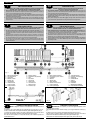
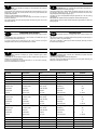
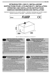
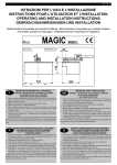
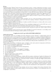
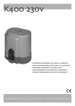
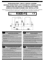
Pag. 1 di 8
ISTRUZIONI PER L'USO E L’INSTALLAZIONE
INSTRUCTIONS POUR L'UTILISATION ET L’INSTALLATION
OPERATING AND INSTALLATION INSTRUCTIONS
GEBRAUCHSANWEISUNGEN UND INSTALLATION
Elettroriduttore irreversibile per cancelli scorrevoli - Motoréducteur irreversible pour portails coulissantes
Irreversible actuator for sliding gates - Selbsthemmender Torantrieb für Schiebetoren
Mod.
K600-FE
Misure in mm - Mesures en mm - Measurements in mm - Abmessungen in mm
I
IMPORTANTI ISTRUZIONI PER LA SICUREZZA
ATTENZIONE - É IMPORTANTE PER LA SICUREZZA DELLE PERSONE
CHE VENGANO SEGUITE TUTTE LE ISTRUZIONI
CONSERVARE CON CURA QUESTE ISTRUZIONI
1° - Tenete i comandi dell'automatismo (pulsantiera, telecomando etc.) fuori dalla portata dei
bambini. I comandi devono essere posti ad un’altezza minima di 1,5mt dal suolo e fuori dal
raggio d’azione delle parti mobili.
2° - Effettuare le operazioni di comando da punti ove l'automazione sia visibile.
3° - Utilizzare i telecomandi solo in vista dell'automazione.
4° - Prima di eseguire qualsiasi operazione di installazione, regolazione, manutenzione
dell’impianto, togliere la tensione agendo sull’apposito interruttore magnetotermico collegato
a monte dello stesso.
5° - Avvertenze: Sulle altre misure di Protezione contro rischi attinenti l'installazione o
l'utilizzazione del Prodotto vedi, a completamento di questo libretto di Istruzioni, le
Avvertenze RIB allegate.
Qualora queste non siano pervenute chiederne l'immediato invio all'Ufficio Commerciale RIB.
LA DITTA RIB NON ACCETTA NESSUNA RESPONSABILITÀ per eventuali danni provocati
dalla mancata osservanza nell'installazione delle norme di sicurezza e le leggi attualmente in
vigore.
F
INSTRUCTIONS IMPORTANTES POUR LA SECURITE
IL EST IMPORTANT POUR LA SECURITE DES PERSONNES
DE SUIVRE ATTENTIVEMENT TOUTES INSTRUCTIONS
GARDER MODE D’EMPLOI
1° - Gardez les commandes de l'automatisme (boutons poussoirs, télécommande etc.) hors
de la portée des enfants. Les commandes doivent être placées au minimum à 1,5 m du
sol, et hors de rayon d’action des pièces mobiles.
2° - Il faut donner les commandes d'un lieu, où on peut voir la porte.
3° - Il faut utiliser les émetteurs seulement si on voit la porte.
4° - Avant d’exécuter quelconques opérationd’installation, réglage, entrietien de l’installation,
couper la tension avec l’interrupteur magnétothermique approprié connecté en amont.
5° - Avertissements: Sur les autres mesures de Protection contre les risques relatifs a
l'installation ou l'utilisation du Produit, voir, à titre de complément de ce livret
d'instructions, les Avertissements RIB ci-jointes. Dans le cas où celles-ci ne vous
seraient pas parvenues, en demander l'envoi immédiat au Bureau d’Exportation de RIB.
L'ENTREPRISE R.I.B. N'ACCEPTE AUCUNE RESPONSABILITÉ pour des dommages
éventuels provoqués par le manque d'observation lors de l'installation des normes de
sécurité et lois actuellement en vigueur.
IMPORTANT SAFETY INSTRUCTIONS
GB
WARNING - IT IS IMPORTANT FOR THE SAFETY OF PERSONS
TO FOLLOW ALL INSTRUCTIONS
SAVE THESE INSTRUCTIONS
1° - Keep the automatic control (push-button, remote control, etc) out of the reach of
children. The control systems must be installed at a minimum hight of 1.5m from
the ground surface and not interfere with the mobile parts.
2° - Command pulses must be given from sites, where you can see the gate.
3° - Use transmitters only if you can see the gate.
4° - Before starting any installation and operation or maintenance work make sure to
cut off power supply by turning the general magnetothermic switch off.
5° - Warnings: when you have finished reading this instruction booklet, please refer to
the RIB instructions attached for the other precautionary measures against risks
connected with the installation or use of the product. If you have not received
these, ask RIB Export Office to send them immediately.
R.I.B. IS NOT LIABLE for any damage caused by not following the safety regulations
and laws at present in force not being observed during installation.
D
WICHTIGE ANWEISUNGEN FÜR DIE SICHERHEIT
ACHTUNG - UM DIE SICHERHEIT VON PERSONEN VOLLKOMMEN
GARANTIEREN ZU KöNNEN, IST ES WICHTIG, DASS ALLE
INSTALLATIONSVORSCHRIFTEN BEACHTET WERDEN
1° - Bewahren Sie die Geräte für die automatische Bedienung (Drucktaster, Funksender,
u.s.w.) an einem für Kinder unzugänglichen Platz auf. Die Steuerungen müssen auf
einer Mindesthöhe von 1,5 m angebracht werden und sich ausserhalb der Raumes
der bewegenden Teile befinden.
2° - Die automatische Steuerung darf nur bedient werden, wenn das Tor sichtbar ist.
3° - Die Funksender nur benützen, wenn das Tor sichtbar ist.
4° - Bevor Sie eine Installation oder Wartungsarbeit an der Anlage durchführen, müssen
Sie kontrollieren, dass die Anlage spannungsfrei geschaltet ist.
5° - Achtung: Für weitere Schutzmaßnahmen im Rahmen der Installation und Anwendung
der Produkte siehe die beiliegenden RlB-Sicherheitshinweise, die diese
Gebrauchsanleitung ergänzen. Sollten Sie diese nicht erhalten haben, fordern Sie sie
bitte sofort bei der RlB Exportabteilung an.
R.I.B. HAFTET NICHT für eventuelle Schäden, die bei der Installation durch
Nichtbeachtung der jeweils gültigen Sicherheitsvorschriften entstehen.
Pag. 2 di 8
I
IMPORTANTI ISTRUZIONI DI SICUREZZA
PER L’INSTALLAZIONE
ATTENZIONE - UNA SCORRETTA INSTALLAZIONE PUÓ PORTARE A DANNI RILEVANTI
SEGUIRE TUTTE LE ISTRUZIONI PER UNA CORRETTA INSTALLAZIONE
1° - Questo libretto d'istruzioni è rivolto esclusivamente a del personale specializzato che sia a
conoscenza dei criteri costruttivi e dei dispositivi di protezione contro gli infortuni per i cancelli, le
porte e i portoni motorizzati (attenersi alle norme e alle leggi vigenti).
2° - Se non é previsto nella centralina elettrica, installare a monte della medesima un'interruttore di tipo
magnetotermico (onnipolare con apertura minima dei contatti pari a 3mm) che riporti un marchio di
conformità alle normative internazionali.
3° - Per la sezione ed il tipo dei cavi la RIB consiglia di utilizzare un cavo di tipo NPI07VVF con sezione
minima di 1,5mm2 e comunque di attenersi alla norma IEC 364 e alle norme di installazione vigenti
nel proprio Paese.
F
IMPORTANT MODE D’EMPLOI DE SECURITE
POUR L’INSTALLATION
ATTENTION - UNE INSTALLATION INCORRECTE PEUT CAUSER DE GRANDS DOMMAGES
SUIVRE TOUTES INSTRUCTIONS POUR UNE CORRECTE INSTALLATION
1° - Ce manuel d'instruction est adressé seulement au personnel specialisé qui a une
connaissance des critères de construction et des dispositifs de protection contre les accidents en ce
qui concerne les portails, les portes et les portes cochères motorisées (suivre les normes et les lois
en vigueur).
2° - A fin de procéder à l'entretien des parties électriques, connecter à l'installation un disjoncteur
differentiel magneto thermique (qui disconnait toutes les branchements de la ligne avec ouverture
min. des branchements de 3 mm ) et qui soit conforme aux normes internationales.
3° - Pour la section et le type des câbles à installer nous vous conseillons d’utiliser un cable <HAR>
avec une section min de 1,5 mm2 en respectant quand même la norme IEC 364 et les normes
nationales d'installation.
GB
IMPORTANT SAFETY INSTRUCTION
FOR INSTALLATION
WARNING -INCORRECT INSTALLATION CAN LEAD TO SEVERE INJURY
FOLLOW ALL INSTALLATION INSTRUCTIONS
1° - This instruction booklet is exclusively dedicated to specialized staff who are aware of the
construction criteria and of the accident prevention protection devices for motorized gates and
doors (according to the current regulations and laws).
2° - To maintain electrical parts safely it is advisable to equip the installation with a differential thermal
magnetic switch (onnipolar with a minimum opening of the contacts of 3mm) and must comply
with the international rules.
3° - As for electric cable type and section RIB suggests cable type <HAR> with minimum section of
1,5mm2 and however respect IEC 364 rule and general national security regulations.
D
WICHTIGE SICHERHEITSVORSCHRIFTEN
FÜR DIE INSTALLATION
ACHTUNG - EINE FALSCHE INSTALLATION KANN ZU BEDEUTENDEN SHÄDEN FÜHREN
FÜR EINE KORREKTE ANLAGE ALLE ANWEISUNGEN BEFOLGEN
1° - Diese Montageanweisung ist ausschließlich für geschultes Fachpersonal bestimmt, das
mit den Montagevorschriften und den Schutzvorrichtungen zur Verhinderung von Unfällen bei
motorisierten Toren vertraut ist (nach den aktuellen Normen und Gesetzen).
2° - Für die Wartung der elektrischen Teile ist es ratsam, zwischen der Anlage und dem
Netzanschluß einen magnetisch-thermischen Differenzialschalter (mit Mindestöffnung aller
Kontakte von 3 mm) zu montieren, der allen internationalen Normen entspricht.
3° - Für den Kabelquerschnitt und die Kabeltypen halten Sie sich an den Normen IEC 364 (MindestKabelquerschnitt von 1,5 mm2 mit der Bezeichnung <HAR>) und für die Montage an die Normen
des jeweiligen Landes.
Fig. 1
ABCDEFGLM-
Elettroriduttore K600-FE
Fotocellule esterne
Cremagliera
Selettore a chiave
Antenna radio
Lampeggiatore
Limitatori di corsa
Costa meccanica
Costa pneumatica
ABCDEFGLM-
K600-FE operator
Photoelectric cells (external)
Rack
Key selector
Tuned aerial
Flashing lamp
Limit switch cam
Mechanical strip
Pneumatic strip
Electro-réducteur K600-FE
Photocellules p/protec. externe
Cremaillere
Selecteur
Antenne radio
Signal electrique
Camme en fin de course
Cordon mécanique
Cordon pneumatique
ABCDEF GL M-
Torantrieb K600-FE
Photozelle Toraussenseitig
Zahnstange
Schlußelschalter
Antenne
Blinkleuchte
Endschalter
Mechanische Kontaktleiste
Pneumatische Kontaktleiste
Fig. 3
Fig. 2
I
A B CDE F GL M-
CONTROLLO PRE-INSTALLAZIONE
N.B. È obbligatorio uniformare le caratteristiche del cancello alle norme e
leggi vigenti.
É necessario che la guida abbia alle sue estremità due fermi meccanici (L) (Fig. 2).
Inoltre, le colonne devono avere superiormente delle guide antideragliamento (Fig. 3).
Il cancello deve essere protetto da involontari sganciamenti e deve muoversi senza
attriti. N.B.: Eliminare fermi meccanici del tipo indicato descritto in figura 3.
Non devono essere presenti, al di sopra del cancello, fermi meccanici perché non
sufficientemente sicuri.
GB
PRE-INSTALLATION CHECKS
ATTENTION: It is compulsory to conform the gate characteristics to the
current regulations and laws.
The guide needs to have two mechanical stops (L) of the type indicated at its ends (Fig.
2).
In addition, the columns must have anti-deraillement guides at the top (Fig. 3).
The gate must be protected against unintentional derailment and must move without
frictions. N.B. Eliminate the mechanical stops of the type indicated in Fig. 3.
There must be no mechanical stops above the gate, as they are not safe enough.
Pag. 3 di 8
CONTROLE PRE-INSTALLATION
F
N.B.: Il est obligatoire d’adapter les caracteristiques du portail aux
normes et lois en vigueur.
Il est nécessaire que le guidage ait à ses extrémités deux arrêts mécaniques (L) du type
indiqué (Fig. 2). En plus, les colonnes doivent avoir dans la partie supérieure des
guidages antidéraillement.
Eliminer les arrêts mécaniques du type décrit (Fig. 3).
Le portail doit être protégé contre des décrochages involontaires et doit pouvoir
manoeuvrer sans effort.
Ces arrêts mécaniques ne doivent pas être présents au-dessus du portail, car ils ne son
pas suffisamment sûrs.
I
ACHTUNG: Mann ist verpflichtet die Eigenschaften des Gittertures zu
die Gesetznormen in Einklang zu bringen.
Die Führungsschiene muß an beiden Enden mechanische Sperrunger (L) haben, wie in
der Abbildung dargestellt ist (Fig. 2). Darüberhinaus Mußen die Saulen über
Entgleisungsschutzvorrichtungen verfugen (Fig. 3).
Das Gitter soll gegen unvorgesehenes Entkuppeln geschützt sein und ohne reibung
nicht bewegen.
Bitte beachten Sie: Entfernen Sie die beschriebenen mechanischen Sperrungen.
Über das Gittertor dürfen sich keine mechanischen Sperrungen befinden, da diese nicht
sicher genug sind.
CARATTERISTICHE TECNICHE
GB
Motoriduttore irreversibile per cancelli scorrevoli aventi un peso massimo
di 600 Kg.
L'irreversibilità di questo motoriduttore fa si che il cancello non richieda alcun tipo di
serratura elettrica per un'efficace chiusura.
Il motore è protetto da una sonda termica che in caso di utilizzo prolungato
dell'apparecchiatura, interrompe momentaneamente il movimento.
F
TECHNICAL DATA
Irreversible ratiomotor for sliding gates with a maximum weight of 600
Kg.
The fact that this ratiomotor is irreversible means that the gate does not need any type of
electric lock in order for it to close efficiently.
The motor is protected by a thermal probe which momentarily interrupts movement
should there be prolonged use.
CARACTERISTIQUES TECHNIQUES
Moto-réducteur irréversible pour portails coulissants ayant un poids
maximum de 600 Kg.
L’irréversibilité de ce moto-réducteur fait que le portail ne requiert aucun type de serrure
électrique pour une fermeture efficace.
Le moteur est protégé par une sonde thermique qui, en cas d’emploi prolongé,
interrompt momentanément le mouvement.
PRÜFUNG VON DER MONTAGE
D
TECHNISCHE EIGENSCHAFTEN
D
Selbsthemmender Torantrieb der für Schiebetoren mit einem maximalen
Gewicht von 600 Kg geeignet ist.
Dieser Motortyp benötigt kein zusätzliches Elektroschloß.
Der Motor ist durch eine Wärmesonde geschützt, die bei längerer Benutzung die
Bewegung vorübergehend unterbricht.
CARATTERISTICHE
TECNICHE
CARACTERISTIQUES
TECHNIQUES
TECHNICAL
DATA
TECHNISCHE
EIGENSCHAFTEN
Peso max cancello
Poids maxi du portail
Max. leaf weight
Max. Torgewicht
K600-FE
Kg
600
Velocità di traino
Vitesse de traction
Operating speed
Laufgeschwindigkeit
m/sec
Forza max di spinta
Force maxi de poussée
Thrust force
Max. Schubkraft
N
0,155÷0,18
Cremagliera modulo
Module crémaillère
Rack
Zahnstange Modul
Alimentazione e frequenza CEE
Alimentation et frequence CEE
EEC Power supply
Stromspannung und frequenz CEE
Potenza motore
Puissance moteur
Motor capacity
Motorleistung
W
237
Assorbimento
Absorption
Power absorbed
Stromaufnahme
A
1,032
Condensatore
Condensateur
Capacitor
Kondensator
µF
10
n° di cicli
Nbre de cycles
No. cycles
Anzahl der Zyklen
n°
Alimentazione e frequenza
Alimentation et frequence
Power supply
Stromspannung und frequenz
Potenza motore
Puissance moteur
Motor capacity
Motorleistung
W
295
Assorbimento
Absorption
Power absorbed
Stromaufnahme
A
1,35
Condensatore
Condensateur
Capacitor
Kondensator
µF
10
n° di cicli
Nbre de cycles
No. cycles
Anzahl der Zyklen
n°
10 - 32s/2s
Alimentazione e frequenza
Alimentation et frequence
Power supply
Stromspannung und frequenz
Potenza motore
Puissance moteur
Motor capacity
Motorleistung
W
243
Assorbimento
Absorption
Power absorbed
Stromaufnahme
A
2,4
Condensatore
Condensateur
Capacitor
Kondensator
µF
80
n° di cicli
Nbre de cycles
No. cycles
Anzahl der Zyklen
n°
10 - 32s/2s
Lubrificazione a grasso
Graisse
Grease
Schmiere
Peso max
Poids maximun
Weight of electroreducer
Motorgewicht
Kg
Rumorosità
Bruit
Noise
Geräusch
db
<70
Volume
Volume
Volume
Volumen
m3
0,029
Grado di protezione
Indìce de protection
Protection
Schutzart
IP
545
290
4
230V~ 50Hz
9 - 38s/2s
220V~ 60Hz
110V~ 60Hz
Bechem - RHUS 550
9,5
Pag. 4 di 8
I
FISSAGGIO MOTORE E CREMAGLIERA
La cremagliera va fissata a una certa altezza rispetto all’appoggio del
motore.
Questa altezza può essere variata grazie a delle asole presenti sulla cremagliera.
Le cremagliere non devono essere saldate, ma solo fissate con delle viti filettate al
cancello.
La registrazione in altezza viene fatta affinché il cancello durante il movimento, non si
appoggi sull'ingranaggio di trazione del riduttore (Fig. 4,5).
Per fissare la cremagliera sul cancello si eseguono dei fori di Ø 7 mm e si filettano
utilizzando un maschio del tipo M8.
L'ingranaggio di traino deve avere circa da 0,5 a 1 mm di agio rispetto alla cremagliera.
F
INSTALLATION DU MOTOR E DE LA CREMAILLERE
La crémaillère doit être fixée à une certaine hauteur par rapport à la
base du moteur.
Cette hauteur peut être modifiée grâce à des boutonnières qui sont présentes sur la
crémaillère. La crémaillère ne doit pas être soudée mais seulement fixée avec des vis
filetées à la grille.
Le réglage en hauteur est effectué afin que le portail ne s'appuie pas sur l'engrenage de
traction du réducteur (Fig. 4,5).
Afin de fixer la crémaillère sur la grille, on perce des trous de 7 mm de diamètre et on les
filète en employant un taraud du type M8.
L'engrenage de tirage doit avoir un jeu de 0,5 à 1 mm en rapport à la crémaillère.
GB
MOTOR AND RACK INSTALLATION
The rack must be fixed at a certain height with respect to the motor base.
This height can be varied thanks to the slots on the rack.
The rack must not be welded, but simply fixed to the gate with threaded screws.
The height needs to be adjusted so that the gate does not rest on the reduction unit
traction gear (Fig. 4,5).
Holes with a diameter of 7 mm should be made to fix the rack into the gate, and they
should be threaded using a M8 type screw tap.
The pinion must have a clearance of 0,5 to 1 mm with respect to the rack.
D
INSTALLATION DES ANTRIEBS UND DER ZAHNSTANGE
Die Zahnstange muß in bestimmten Abstand von der
Verankerungsplatte befestigt werden.
Die Höhe kann mit Hilfe der auf der Zahnstange befindlichen Ösen verstellt werden.
Die Zahnstange darf nicht angeschweißt, sondern nur mit Hilfe von Gewindeschrauben
an dem Gittertor befestigt werden.
Die Höheneinstellung soll verhindern, daß das Gittertor auf dem Antriebszahnrad des
Antriebes aufliegt. (Abb. 4,5).
Um die Zahnstange am der Gittertor fixieren werden Locher mit einem Durchmesser von
7 mm gebohrt, in die ein Gewinde M8 eingeschnitten wird.
Das Zugzahnrad muß gegenüber der Zahnstange ein Spiel von 0,5 bis 1 mm haben.
Misure in mm
Mesures en mm
Measurements in mm
Abmessungen in mm
Fig. 4
Fig. 5
A) Cancello
Portail coulissant
Sliding gate
Schiebetoren
B) Fotocellule esterne
Cellules pour l'exterieur
External photo-electric cells
Photozelle - Außenseitig
L) Costa meccanica fissa sulle colonne
Cordon mécanique fixé sur pilier
Safety strip fixed to column
Sicherheitskontaktleiste auf dem Schiebetor
I) Fotocellula per protezione interna
Photocellules p/protection interne
Photo electric cells (internal)
Photozelle - Torinnenseitig
Fig. 6
I
SICUREZZE ELETTRICHE
Realizzare l’impianto in ottemperanza alle norme ed alle leggi vigenti.
Si consiglia l'utilizzo della centralina elettronica di comando EURO11-FE (per 1 motore
monofase).
Per i collegamenti ed i dati tecnici degli accessori attenersi ai relativi libretti.
F
SECURITES ELECTRIQUES
Adapter les installation du parties electriques aux normes et lois en
vigueur.
Nous vous conseillons d’utiliser le coffret électronique EURO11-FE (pour 1 moteur
monophasés). Pour ce qui est des raccordements et des données techniques des
accessoires, se référer à leur manuel.
GB
ELECTRIC SAFETY DEVICES
The installation must be installed according to the current regulations and
laws.
Use the EURO11-FE (for one single-phase motor) electronic control unit.
For connections and technical data of accessories refer to the appropriate booklets.
D
ELEKTRISCHE SICHERHEITEN
Die Installation muß nach die aktuellen Gesetznormen installiert werden.
Es wird die Verwendung der elektronischen Steuergeräte EURO11-FE (für 1 einphasige
Motor) empfohlen.
Für die Anschlüsse und technische Daten der Zubehörteilen verweisen wir auf die
entsprechenden Bedienungshandbücher.
Pag. 5 di 8
I
SBLOCCO D'EMERGENZA
Da effettuare dopo aver tolto l'alimentazione elettrica al motore.
Per poter agire manualmente sul cancello è sufficiente inserire l’apposita chiave e
ruotarla 3 volte in senso antiorario (Fig. 9).
F
GB
EMERGENCY RELEASE
To be undertaken after disconnecting power supply.
To move the gate manually it is necessary to release the operator inserting the special
key and turning it 3 times in the anti-clockwise sense (Fig. 9).
MANOEUVRE DE SECOURS
D
NOTENTRIEGELUNG
Die Wartungsarbeit nur nach der
Ausschliessung der Spannung auszuführen.
Um das Tor des Modells KING manuell zu bedienen, müßen Sie
den dafür vorgesehenen Schlußel in das Schloß stecken und ihn
dreimal entgegen dem Uhrzeigersinn drehen (Abb. 9).
Effectuer seulement apres avoir coupé
l'alimentation.
Pour actionner le portail manuellement il est necessaire introduire
la clé appropriée dans la serrure et la tourner 3 fois dans le sense
anti-horarie (Fig.9).
Fig. 7
F
REGLAGE FIN DE COURSE
GB
LIMIT SWITCH ADJUSTMENT
D
EINSTELLUNG DES ENDSCHALTERS
GB
SAFETY CLUTCH ADJUSTMENT
D
EINSTELLUNG DER RUTSCHKUPPLUNG
L'arrêt du portail est obtenu avec 2 cames montées aux extrémités de la
crémaillère (Fig. 8).
Le réglage de la course d'ouverture et de fermeture s'obtient en déplaçant la came sur
les dents de la crémaillère.
Pour fixer la came au support, visser à fond les vis-tarauds (B).
Pour bloquer le support came à la crémaillère, visser à fond le vis (A).
N B. Avec les fins de course électriques, il faut monter des butées mécaniques a fin que
le portail ne sorte pas de son guide supérieur.
The gate stops thanks to the two cams, which are placed at each end of
the rack (Fig. 8).
The regulation of the opening and closing stroke can be obtained by displacing these on
the rack.
Insert and tighten self-tapping screw fully (B) to secure the two cams to their mounting
brachets.
Insert and tighten the screw (A) fully to secure the brackets to the rack.
N.B.: In addition to the above-mentioned limit switch it is compulsory to install solid
mechanical stops, which prevent the gate from sliding off the upper guide bearings.
Fig. 8
I
REGOLAZIONE FINECORSA
I
REGOLAZIONE FRIZIONE
F
REGLAGE DE L'EMBRAYAGE DE SECURITE
L'arresto del cancello avviene attraverso le due camme montate alle
estremità della cremagliera (Fig. 8).
La regolazione della corsa di apertura e chiusura, si ottiene spostando le medesime sui
denti della cremagliera.
Per fissare la camma al supporto avvitare a fondo le viti autofilettanti (B).
Per bloccare il supporto camma alla cremagliera avvitare a fondo le viti (A).
N.B: Oltre alle camme di fermo elettrico sopraesposte è obbligatoria l'installazione di
fermi meccanici robusti che non permettono la fuori uscita del cancello dalle guide
superiori (Per l'Italia NORME UNI 8612).
Nel K600-FE il limitatore di coppia meccanico non è presente.
É quindi necessario comandare questo attuatore con un quadro elettronico (EURO11FE) dotato di limitatore di coppia elettrico.
Le K600-FE n'est pas pourvu de limitateur de couple mécanique.
Il est donc necessarie de commander ce motoréducteur au moyen d'un coffret
électronique (EURO11-FE) doté de limitateur de couple électrique.
Der Toranschlag ist mit zwei Metallbügeln, die an der Zahnstange
angebracht sind, gegeben (Abb. 8).
Die Weite der Toröffnung erfolgt mit der Verstellung der Metallbügeln.
Zur Befestigung des Nockens auf der Halterung sind die selbstschneidenden Schrauben
bis zum Anschlag festzuziehen (B).
Zur Befestigung der Nockenhalterung an der Zahnstange sind die Schrauben bis zum
Anschleg festzuziehen (A)
N.B. Außer dem oben beschriebenen Metallbügeln ist eine mechanische
Feststellvorrichtung vorgeschrieben, um eine Torentgleisung verhindern zu konnen.
There is no mechanical safety clutch with the K600-FE.
Therefore it is necessary to operate this actuator with an electronic control panel
(AQM22-FE o EURO22-FE) fitted with a safety clutch (tension regulator).
Bei K600-FE ist keine mechanische Rutschkupplung vorhanden.
Es ist daher notwendig, diesen Torantrieb mittels einer elektronischen Rutschkupplung
(EURO11-FE) ausgerüstet ist.
Pag. 6 di 8
MANUTENZIONE
I
Da effettuare solamente da parte di personale specializzato dopo
aver tolto l'alimentazione elettrica al motore.
Pulire periodicamente, a cancello fermo, la guida di scorrimento da sassi e altra
sporcizia.
In caso di problemi nell'installazione consultare la "TABELLA DEI POSSIBILI
PROBLEMI".
F
ENTRETIEN
Effectuer soulement par personnel specialisé après avoir coupé
l'alimentation.
Seulement quand le portail n'est pas en mouvement nettoyer périodiquement la glissière
afin d'en enlever les cailloux et autre saleté.
En cas de difficultés lors de l'installation, consulter le "TABLEAU DES DIFFICULTES
POSSIBLES".
TABELLA DEI POSSIBILI PROBLEMI
I
Problema
GB
MAINTENANCE
To be undertaken only by specialized staff after disconnecting
power supply.
Clean the sliding guide of stones and dirt periodically only when the gate does not move.
If there are any problems during installation, consult the "LIST OF POSSIBLE
PROBLEMS".
D
WARTUNG
GB
LIST OF POSSIBLE PROBLEMS
Die Wartungsarbeit nur durch spezialiesierten Fachleuten nach der
Ausschliessung der Spannung auszuführen.
Saubern Sie regelmäßig beim nicht bewegenden Tor die Laufschiene von Steinen oder
anderem Schmutz.
Sofern Installationsprobleme auftreten, ziehen Sie die "TABELLE VON EVENTUELLEN
PROBLEMEN" zu Rate.
Soluzione
Problem
Solution
K600-FE non apre, ma chiude
Invertire V con W
K600-FE does not open, but closes
K600-FE non si ferma sui finecorsa
Invertire il filo 4 col filo 7 sul quadro
elettronico
K600-FE does not stop on the limit Invert 4 instead 7 on the electronic panel
switches
K600-FE non ha forza di traino
Agire sulla frizione tanto quanto basta a
ripristinare il moto del cancello senza
forzarlo (Fig. 9).
K600-FE has not the force to move the Operate the clutch as much as i
gate
necessary to reset the gate movement
without forcing it (Fig. 9).
K600-FE non funziona
Controllare l'alimentazione.
The motor does not work
Control the connections
K600-FE dopo pochi secondi si ferma
Regolare il tempo di funzionamento sul
quadro elettronico
The motor stops after few seconds
Adjust the operating timer on the control
box
F
TABLEAU DES DIFFICULTES POSSIBLES
Problème
K600-FE n'ouvre pas, mais il ferme
Inverser V avec W
K600-FE n'a pas de force de traction
Opérer sur l'embrayage autant qu'il faut
afin de rétablir le mouvement du portail
sans le forcer (Fig. 9)
K600-FE ne fonctionne pas
Controler l'alimentation.
K600-FE s'ârrete après quelques Régler le timer de fonctionnement sur le
secondes.
coffret électronique.
N.B.:É obbligatoria la messa a terra dell'impianto
I dati descritti nel presente manuale sono puramente indicativi.
La RIB si riserva di modificarli in qualsiasi momento.
Realizzare l’impianto in ottemperanza alle norme ed alle leggi vigenti.
F
N.B:La mise à la terre de l'installation est obligatoire
Les donnees techniques decrites dans ce present manuel sont purement
a titre indicatif.
La RIB se reserve le droit de les modifier à n'importe quel moment.
Adapter les installation du parties electriques aux normes et lois en vigueur.
TABELLE EVENTUELL AUFTRETENDER PROBLEME
Probleme
Solution
K600-FE ne s'ârrette pas sur les fins de Inverser 4 avec 7 sur le coffret
course
électronique
I
D
Invert on the motor V instead W
Lösung
K600-FE öffnet nicht, sondern schließt Invertieren Sie V und W.
nur.
K600-FE halt bei den Endschaltern nicht Invertieren sie 4 und 7 auf die
an.
Anschlußklemme
K600-FE hält keine Zugkraft.
Betatigen Sie die Kupplung so lange bis
das Tor sich wieder normal bewegt, ohne
es dabei zu belasten (Abb. 9).
Der K600-FE funktioniert nicht.
Überprüfen Sie die Stromversorgung.
Der K600-FE hält nach wenigen Stellen Sie den Timer richtig ein.
Sekunden an.
GB
N.B.: The system absolutely must be earthed.
The technical data given in this manual are only aproximate.
RIB reserves the right to modify technical data at any time without previous notice.
The installation must be installed according to the current regulations and laws.
D
Bitte beachten Sie: Das Erden der Anlage ist obligatorish
Die in dem vorliegenden Handbuch angegebenen technischen Dater sind
rein informativ.
Firma RIB behalt sich das Rech vor, sie jederzeit zu ändern.
Die Installation muß nach die aktuellen Gesetznormen installiert werden.
Pag. 7 di 8
cod: ACG4655
Kit fissaggio per K400 e K600 - Fixing Set for K400 and K600
Kit de fixation pour K400 et K600 - Befestigung Installationssatz für K400 und K600
cod: ACG8107
Piastra da cementare - Base Plate
Plaque á Sceller - Unterflürplatte
*Ruote con gola tonda - Wheels with Round grove - Galets avec gorge ronde - Räder mit
rundem profil
** Ruote con gola a V - Wheels with V grove - Galets avec gorge en V - Räder mit V profil
*** Ruota con gola tonda carrellate - Wheel with Round grove and support trolley - Galet
avec gorge ronde et monture pour le support - Räder mit rundem profil und
Stützführungen.
**** Ruote con gola a V carrellate - Wheels with V grove and support trolley - Galets avec
gorge en V et monture pour le support - Räder mit V profil und Stützführungen.
*
*
**
**
**
***
****
****
****
ACG4000
ACG4015
ACG4020
ACG4040
ACG4060
ACG4100
ACG4030
ACG4050
ACG4070
Ø100
Ø120
Ø120
Ø160
Ø200
Ø90
Ø120
Ø160
Ø200
ACG4080+ACG4090
Guida omega - Omega rail - rail omega - Führung Omega
cod: ACS9000 2mt (2mt x 1)
cod: ACS9001 10mt (1mt x 10)
Cremagliera nylon - Nylon Rack
Cremaillere en nylon - Kunststoff-Zahnstange
ACG4010
Oliva in Nylon
Nylon Olive
Olive en nylon
Tragspuhrhalter
MOON
2CH TX91
4CH TX91
2CH TX433
4CH TX433
Cod. ACG7025
Cod. ACG7026
Cod. ACG6081
Cod. ACG6082
Nr: B 01 05 40744 002
- Dichiariamo sotto la nostra responsabilità che questa
apparecchiatura é conforme alle segueti norme e Direttive:
- Cet appareil se conforme aux normes suivantes:
- We declare under our responsibilitythat the product is conform to
the following standards:
- Dieses Gerät entspricht den folgenden Normen:
UNI8612
EN50081-1
EN50081-2
EN50082-1
EN50082-2
EN60335-1 II Ed.
1989
1997
1997
1992
1992
1995
- Come richiesto dalle seguenti Direttive:
- Comme demandé par les suivantes Directives:
- As requested by the following Directives:
- Gemaß den folgenden Richtlinien:
EC 89/336
EC 92/31
EC 93/68
EC 73/23
Le centraline EURO versione CRX possono essere attivate solo da telecomandi RIB
con frequenza 433,92MHz.
Le centraline EURO non CRX permettono l’inserimento di un qualunque ricevitore
compatibile attivabile dal relativo telecomando.
Les armoires de commande EURO version CRX ne peuvent être commandées que
par l’émetteur RIB 433,92MHz.
Les armoires de commande non CRX permettent l’embrochage d’un recepteur RIB
12Vdc commandé par un emetteur approprié.
CRX type EURO control units can only be operated using RIB remote controls with a
frequency of 433.92MHz.
Non-CRX EURO control units can be used with any type of compatible receiver that
will respond to the relative remote control.
Die Schalttafeln EURO Typ CRX können nur durch RIB Fernbedienungen mit
Frequenz 433,92 MHz aktiviert werden.
Die Steuertafeln EURO, die vom Typ CRX verschieden sind, erlauben den Einbau
eines beliebigen kompatiblen Funkempfängers, der durch die entsprechende
Fernbedienung aktivierbar ist.
Pag. 8 di 8
8 028265 071308 >
K600FEPLUS
BA01019
BA03042
BA03043
BA10024
BC00189
CAL1120
CAL1125
CAL1126
CCM6204ZZ
CEL1385
CEL1424
CEL1445
CEL1519
CEL1521
CFS1004
CME2025
CME2026
Denominazione Particolare
Serie accessori per cilindro
Gruppo finecorsa
Premont. quadro EURO11FECRX
Confezione fermi finecorsa
Circuito forcellino ottico K
Corona elicoidale
Base scorrevole
Guscio superiore
Cuscinetto motore
Condensatore 8µF 450V
Condensatore 80µF 450V
Microswitch
Passacavo IP55 GW50431 AC50
Passacavo IP55 GW50429 AC
Ingranaggio di traino
Vite senza fine
Albero traino
Codice
CME2028
CMO2605
CMO2606
CPL1174
CPL1175
CPL1176
CPL1177
CPL1178
CPL1179
CPL1218
CPL1219
CPL1220
CPL1221
CPL1224
CTC1012
CTC1018
CTC1152
Denominazione Particolare
Perno di sblocco
Motore K600FE 230V - 50/60Hz
Motore K600FE 110V - 60Hz
Sfera per molla
Porta micro
Perno porta molla
Guida porta micro
Tappo ingranaggio traino
Tappo per carter
Disco Encoder
Coperchio Encoder
Carter K
Flangia finecorsa
Supporto scheda
Chiavetta 8x7x20
Chiavetta 8x7x50
Spina elastica 3x30
®
Codice
CTC1164
CTC1205
CTC1221
CTC1242
CTC1243
CTC1245
CTC1259
CTC1259
CTC1308
CTC1355
CTC1406
CVA1325
CVA1372
25014 CASTENEDOLO (BS)-ITALY
Via Matteotti, 162
Telefono ++39.030.2135811
Telefax ++39.030.21358279-21358278
automatismi per cancelli
automatic entry systems http://www.ribind.it - email: [email protected]
Denominazione Particolare
Spina elastica 6x30
Molla sblocco
Spina cilindrica 10x80
Molla per finecorsa
Guarnizione base K
Spina cilindrica 5x8
Molla trazione coperchio
Molla coperchio finecorsa
Anello di tenuta OR 4100
Anelli di rasamento 25x35x0,5
Paraolio 10x26x7
Cilindro serratura
Boccole flangia 25X32X40X5X25
La presente macchina non può funzionare in modo
indipendente ed è destinata ad essere incorporata in
un impianto costituito da ulteriori elementi. Rientra
perciò nell’Art. 4 paragrafo 2 della Direttiva
89/392/CEE (Macchine) e successive modifiche, per
cui segnaliamo il divieto di messa in servizio prima che
l’impianto sia stato dichiarato conforme alle
disposizioni della Direttiva
Il Presidente
Cod. AA 34660/34650 - 000426 - Rev. 03
Codice