1
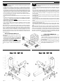
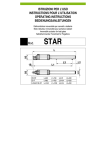
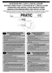
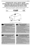
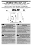
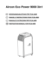
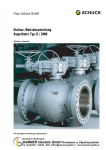
Pag. 1 di 12
ISTRUZIONI PER L'USO E L’INSTALLAZIONE
INSTRUCTIONS POUR L'UTILISATION ET L’INSTALLATION
OPERATING AND INSTALLATION INSTRUCTIONS
GEBRAUCHSANWEISUNGEN UND INSTALLATION
Elettroriduttore irreversibile per cancelli a battente - Moto-réducteur irreversible pour portails à battant
Irreversible actuator for leaf gates - Selbsthemmender Torantrieb für Flugeltore
Mod.
Misure in mm
Mesures en mm
MAGIC IRREV.
Measurements in mm
Abmessungen in mm
Fig. 1
I
IMPORTANTI ISTRUZIONI PER LA SICUREZZA
ATTENZIONE - É IMPORTANTE PER LA SICUREZZA DELLE PERSONE
CHE VENGANO SEGUITE TUTTE LE ISTRUZIONI
CONSERVARE CON CURA QUESTE ISTRUZIONI
1° - Tenete i comandi dell'automatismo (pulsantiera, telecomando etc.) fuori dalla portata dei
bambini. I comandi devono essere posti ad un’altezza minima di 1,5mt dal suolo e fuori dal
raggio d’azione delle parti mobili.
2° - Effettuare le operazioni di comando da punti ove l'automazione sia visibile.
3° - Utilizzare i telecomandi solo in vista dell'automazione.
4° - Prima di eseguire qualsiasi operazione di installazione, regolazione, manutenzione
dell’impianto, togliere la tensione agendo sull’apposito interruttore magnetotermico collegato
a monte dello stesso.
5° - Avvertenze: Sulle altre misure di Protezione contro rischi attinenti l'installazione o
l'utilizzazione del Prodotto vedi, a completamento di questo libretto di Istruzioni, le
Avvertenze RIB allegate.
Qualora queste non siano pervenute chiederne l'immediato invio all'Ufficio Commerciale RIB.
LA DITTA RIB NON ACCETTA NESSUNA RESPONSABILITÀ per eventuali danni provocati
dalla mancata osservanza nell'installazione delle norme di sicurezza e le leggi attualmente in
vigore.
F
INSTRUCTIONS IMPORTANTES POUR LA SECURITE
IL EST IMPORTANT POUR LA SECURITE DES PERSONNES
DE SUIVRE ATTENTIVEMENT TOUTES INSTRUCTIONS
GARDER MODE D’EMPLOI
1° - Gardez les commandes de l'automatisme (boutons poussoirs, télécommande etc.) hors
de la portée des enfants. Les commandes doivent être placées au minimum à 1,5 m du
sol, et hors de rayon d’action des pièces mobiles.
2° - Il faut donner les commandes d'un lieu, où on peut voir la porte.
3° - Il faut utiliser les émetteurs seulement si on voit la porte.
4° - Avant d’exécuter quelconques opérationd’installation, réglage, entrietien de l’installation,
couper la tension avec l’interrupteur magnétothermique approprié connecté en amont.
5° - Avertissements: Sur les autres mesures de Protection contre les risques relatifs a
l'installation ou l'utilisation du Produit, voir, à titre de complément de ce livret
d'instructions, les Avertissements RIB ci-jointes. Dans le cas où celles-ci ne vous
seraient pas parvenues, en demander l'envoi immédiat au Bureau d’Exportation de RIB.
L'ENTREPRISE R.I.B. N'ACCEPTE AUCUNE RESPONSABILITÉ pour des dommages
éventuels provoqués par le manque d'observation lors de l'installation des normes de
sécurité et lois actuellement en vigueur.
GB
IMPORTANT SAFETY INSTRUCTIONS
WARNING - IT IS IMPORTANT FOR THE SAFETY OF PERSONS
TO FOLLOW ALL INSTRUCTIONS
SAVE THESE INSTRUCTIONS
1° - Keep the automatic control (push-button, remote control, etc) out of the reach of
children. The control systems must be installed at a minimum hight of 1.5m from the
ground surface and not interfere with the mobile parts.
2° - Command pulses must be given from sites, where you can see the gate.
3° - Use transmitters only if you can see the gate.
4° - Before starting nay installation and operation or maintenance work make sure to cut
off power supply by turning the general magnetothermic switch off.
5° - Warnings: when you have finished reading this instruction booklet, please refer to
the RIB instructions attached for the other precautionary measures against risks
connected with the installation or use of the product. If you have not received these,
ask RIB Export Office to send them immediately.
R.I.B. IS NOT LIABLE for any damage caused by not following the safety regulations and
laws at present in force not being observed during installation.
D
WICHTIGE ANWEISUNGEN FÜR DIE SICHERHEIT
ACHTUNG - UM DIE SICHERHEIT VON PERSONEN VOLLKOMMEN
GARANTIEREN ZU KöNNEN, IST ES WICHTIG, DASS ALLE
INSTALLATIONSVORSCHRIFTEN BEACHTET WERDEN
1° - Bewahren Sie die Geräte für die automatische Bedienung (Drucktaster, Funksender,
u.s.w.) an einem für Kinder unzugänglichen Platz auf. Die Steuerungen müssen auf
einer Mindesthöhe von 1,5 m angebracht werden und sich ausserhalb der Raumes der
bewegenden Teile befinden.
2° - Die automatische Steuerung darf nur bedient werden, wenn das Tor sichtbar ist.
3° - Die Funksender nur benützen, wenn das Tor sichtbar ist.
4° - Before starting nay installation and operation or maintenance work make sure to cut off
power supply by turning the general magnetothermic switch off.
5° - Achtung: Für weitere Schutzmaßnahmen im Rahmen der Installation und Anwendung
der Produkte siehe die beiliegenden RlB-Sicherheitshinweise, die diese
Gebrauchsanleitung ergänzen. Sollten Sie diese nicht erhalten haben, fordern Sie sie
bitte sofort bei der RlB Exportabteilung an.
R.I.B. HAFTET NICHT für eventuelle Schäden, die bei der Installation durch Nichtbeachtung
der jeweils gültigen Sicherheitsvorschriften entstehen.
Pag. 2 di 12
I
IMPORTANTI ISTRUZIONI DI SICUREZZA
PER L’INSTALLAZIONE
GB
ATTENZIONE - UNA SCORRETTA INSTALLAZIONE PUÓ PORTARE A DANNI RILEVANTI
SEGUIRE TUTTE LE ISTRUZIONI PER UNA CORRETTA INSTALLAZIONE
1° - Questo libretto d'istruzioni è rivolto esclusivamente a del personale specializzato che sia a
conoscenza dei criteri costruttivi e dei dispositivi di protezione contro gli infortuni per i cancelli, le
porte e i portoni motorizzati (attenersi alle norme e alle leggi vigenti).
2° - Se non é previsto nella centralina elettrica, installare a monte della medesima un'interruttore di tipo
magnetotermico (onnipolare con apertura minima dei contatti pari a 3mm) che riporti un marchio di
conformità alle normative internazionali.
3° - Per la sezione ed il tipo dei cavi la RIB consiglia di utilizzare un cavo di tipo NPI07VVF con sezione
minima di 1,5mm2 e comunque di attenersi alla norma IEC 364 e alle norme di installazione vigenti
nel proprio Paese.
F
IMPORTANT MODE D’EMPLOI DE SECURITE
POUR L’INSTALLATION
❶ Elettroriduttore MAGIC
❷ Antenna radio
❸ Lampeggiatore
❹ Fotocellula esterna
❺ Fotocellule interna
❻ Selettore a chiave
WARNING -INCORRECT INSTALLATION CAN LEAD TO SEVERE INJURY
FOLLOW ALL INSTALLATION INSTRUCTIONS
1° - This instruction booklet is exclusively dedicated to specialized staff who are aware of the
construction criteria and of the accident prevention protection devices for motorized gates and
doors (according to the current regulations and laws).
2° - To maintain electrical parts safely it is advisable to equip the installation with a differential thermal
magnetic switch (onnipolar with a minimum opening of the contacts of 3mm) and must comply
with the international rules.
3° - As for electric cable type and section RIB suggests cable type <HAR> with minimum section of
1,5mm2 and however respect IEC 364 rule and general national security regulations.
D
ATTENTION - UNE INSTALLATION INCORRECTE PEUT CAUSER DE GRANDS DOMMAGES
SUIVRE TOUTES INSTRUCTIONS POUR UNE CORRECTE INSTALLATION
1° - Ce manuel d'instruction est adressé seulement au personnel specialisé qui a une
connaissance des critères de construction et des dispositifs de protection contre les accidents en ce
qui concerne les portails, les portes et les portes cochères motorisées (suivre les normes et les lois
en vigueur).
2° - A fin de procéder à l'entretien des parties électriques, connecter à l'installation un disjoncteur
differentiel magneto thermique (qui disconnait toutes les branchements de la ligne avec ouverture
min. des branchements de 3 mm ) et qui soit conforme aux normes internationales.
3° - Pour la section et le type des câbles à installer nous vous conseillons d’utiliser un cable <HAR>
avec une section min de 1,5 mm 2 en respectant quand même la norme IEC 364 et les normes
nationales d'installation.
IMPORTANT SAFETY INSTRUCTION
FOR INSTALLATION
WICHTIGE SICHERHEITSVORSCHRIFTEN
FÜR DIE INSTALLATION
ACHTUNG - EINE FALSCHE INSTALLATION KANN ZU BEDEUTENDE SHADEN FÜHREN.
FÜR EINE KORREKTE ANLAGE ALLE ANWEISUNGEN BEFOLGEN
1° - Diese Montageanweisung ist ausschließlich für geschultes Fachpersonal bestimmt, das
mit den Montagevorschriften und den Schutzvorrichtungen zur Verhinderung von Unfällen bei
motorisierten Toren vertraut ist (nach den aktuellen Normen und Gesetzen).
2° - Für die Wartung der elektrischen Teile ist es ratsam, zwischen der Anlage und dem
Netzanschluß einen magnetisch-thermischen Differenzialschalter (mit Mindestöffnung aller
Kontakte von 3 mm) zu montieren, der alle internationalen Normen entspricht.
3° - Für den Kabelquerschnitt und die Kabeltypen halten Sie sich an den Normen IEC 364 (MindestKabelquerschnitt von 1,5 mm2 mit der Bezeichnung <HAR>) und für die Montage an die Normen
des jeweiligen Landes.
❷
❸
❻
❶ Electro-reducteur MAGIC
❷ Antenne radio
❸ Signal electrique
❹ Photocellules p/protection externe
❺ Photocellules p/protection interne
❻ Selecteur
❺
❺
❶ E-Torantrieb MAGIC
❷ Antenne
❸ Blinkleuchte
❹ Photozelle Toraussenseitig
❺ Photozellen Torinnenseitig
❻ Schlusselschalter
❶
❶
❶ MAGIC operator
❷ Tuned aerial
❸ Flashing lamp
❹ Photoelectric cells (external)
❺ Photoelectric cells (internal)
❻ Key selector
❻
❹
❹
❶
❶
❺
❺
Fig. 2
I
CONTROLLO PRE-INSTALLAZIONE
F
CONTROLE PRE-INSTALLATION
Le ante devono essere solidamente fissate ai cardini delle colonne, non
devono flettere durante il movimento e devono muoversi senza attriti.
Prima d'installare il MAGIC è meglio verificare tutti gli ingombri necessari per poterlo
installare.
Se il cancello si presenta come da Fig. 2 non occorrono modifiche.
N.B. È obbligatorio uniformare le caratteristiche del cancello alle norme e leggi vigenti.
Le portail à battant doit être solidement fixé aux cardans des colonnes,
ne doit pas flechir pendant le mouvement et doit pouvoir manoeuvrer sans effort.
Avant d'installer le MAGIC, il convient de verifier tous les encombrements necessaires
pour proceder à l'installation. Si le portail se presente comme indiqué Fig. 2, aucune
modification n'est necessaire. N.B.: Il est obligatoire d’adapter les caracteristiques du
portail aux normes et lois en vigueur
GB
PRE-INSTALLATION CHECKS
The leaf must be fixed firmily on the hinges to the pillars, must not be
flexible during the movement and must move without frictions.
Before the installation of MAGIC, verify all dimensions etc.
There's no need for any modification, if the gate is like that shown in Fig. 2.
ATTENTION: It is compulsory to conform the gate characteristics to the current
regulations and laws.
D
PRÜFUNG VON DER MONTAGE
Das Flugeltor muß fest an der Angelpunkten der Trager fixiert sein, darf
sich wahrend der Bewegung nicht biegen und ohne reibung nicht bewegen.
Bevor MAGIC montiert wird ist es besser alle Hindernisse, die bei der Montage auftreten
konnen. festzustellen. Bei einem Tor wie in Abbildung 2 mussen keine Veranderungen
vorgenommen werden. ACHTUNG: Mann ist verpflichtet die Eigenschaften des
Gittertures zu die Gesetznormen in Einklang zu bringen
Pag. 3 di 12
CARATTERISTICHE
TECNICHE
CARACTERISTIQUES
TECNIQUES
TECHNICAL
DATA
TECHNISCHE
EIGENSCHAFTEN
Lunghezza max. anta
Longueur maxi du battant
Max. leaf length
Maximale Torflügelweite
mt
2
Peso max cancello
Poids maxi du portail
Max. leaf weight
Maximale Torgewicht
Kg
350
MAGIC
105°
180°
Tempo medio apertura
Temps moyen d'ouverture
Average opening time
Mittlere Offnungszeit
sec.
Coppia max
Couple maxi
Max torque
Maximale Drehmoment
Nm
Alimentazione e frequenza CEE Alimentation et frequence CEE
EEC Power supply
Stromspannung und frequenz CEE
Potenza motore
Puissance moteur
Motor capacity
Motorleistung
W
190
Assorbimento
Absorption
Power absorbed
Stromaufnahme
A
0,8
Condensatore
Condensateur
Capacitor
Kondensator
µF
6,3
n° di cicli
Nbre de cycles
No. cycles
Anzahl der Zyklen
n°
40 - 20s/2s
Alimentazione e frequenza
Alimentation et frequence
Power supply
Stromspannung und frequenz
Potenza motore
Puissance moteur
Motor capacity
Motorleistung
W
200
1
20
40
250
230V~ 50Hz
220V~ 60Hz
Assorbimento
Absorption
Power absorbed
Stromaufnahme
A
Condensatore
Condensateur
Capacitor
Kondensator
µF
6,3
n°
19 - 20s/2s
n° di cicli
Nbre de cycles
No. cycles
Anzahl der Zyklen
Alimentazione e frequenza
Alimentation et frequence
Power supply
Stromspannung und frequenz
Potenza motore
Puissance moteur
Motor capacity
Motorleistung
W
200
Assorbimento
Absorption
Power absorbed
Stromaufnahme
A
1,8
Condensatore
Condensateur
Capacitor
Kondensator
µF
25
n° di cicli
Nbre de cycles
No. cycles
Anzahl der Zyklen
n°
19 - 20s/2s
Tipo di olio
Type d'huile
Lubrification
Ölsorte
Peso max
Poids maximun
Weight of electroreducer
Motorgewicht
Kg
Rumorosità
Bruit
Noise
Geräusch
db
<70
Volume
Volume
Volume
Volumen
m3
0,020
Grado di protezione
Indìce de protection
Protection
Schutzart
IP
677
110V~ 60Hz
Bechem Staroel NR100
21
N° cicli = Numero di manovre complete minime garantite
(apre+chiude), ammettendo un tempo massimo di funzionamento di 20
secondi con 2 secondi di pausa tra i movimenti (tempo massimo di
funzionamento e tempo minimo di pausa tra le manovre settati su centralina RIB DE2).
No. cycles = minimum number of guaranteed complete movements
(open+close), allowing 20 seconds maximum operating time with a two
second pause between movements (maximum operating time and
minimum pause time for the movements set on the RIB DE2 control board).
Il N° cicli aumenta quanto più breve è il tempo di funzionamento e lungo il tempo di
pausa tra le manovre.
The number of cycles increases as the operation time decreases, with respect to the
pause time between movements.
N° cicli = N° di manovre complete conteggiate fino al raggiungimento di una
temperatura del motore di 125°C (con motore a pieno carico con temperatura di avvio
di 25°C).
No. cycles = number of complete movements carried out before the motor
temperature reaches 125°C (with motor at full load and starting temperature of 25°C).
I
N° cicli = Non indica che il motore subito dopo aver eseguito queste manovre vada
in termica.
GB
No. cycles = the motor shows no sign of overheating after completing these
cycles.
Nbre de cycles = Nbre minimum de manoeuvres complètes
garanties (ouverture + fermeture), en admettant un temps maximum de
fonctionnement de 20 secondes avec 2 secondes de pause entre les
mouvements (temps maximum de fonctionnement et temps minimum de pause entre les
mouvements programmés sur le coffret électronique RIB DE2).
Anzahl der Zyklen = Mindestanzahl der garantierten kompletten
Bewegungen (Öffnen + Schließen), wobei die max. Betriebszeit 20
Sekunden mit 2 Sekunden Pause zwischen den Bewegungen (auf der
Steuertafel RIB DE2 programmierte max. Betriebszeit und minimale Pause zwischen den
Bewegungen).
Plus le temps de fonctionnement est bref et plus le temps de pause entre les
manoeuvres est long, plus le nombre de cycles augmente.
Die Zyklenanzahl erhöht sich, wenn die Betriebszeit kürzer und die Pause zwischen den
Bewegungen länger wird.
Nbre de cycles = Nbre de manoeuvres complètes comptées avant que le moteur
n’ait atteint une température de 125 °C (avec moteur à pleine puissance et
température de démarrage de 25 °C).
Anzahl der Zyklen = Anzahl der kompletten Bewegungen bis der Motor eine
Temperatur von 125°C erreicht (bei voller Motorleistung mit einer Anfangstemperatur
von 25°C).
Nbre de cycles = Ne signifie pas que le moteur se met en veille immédiatement
après l’exécution de ces manoeuvres.
Anzahl der Zyklen = Zeigt nicht an, daß der Motor sofort nach diesen Bewegungen
blockiert wird.
F
D
Pag. 4 di 12
I
CARATTERISTICHE TECNICHE MOTORIDUTTORE
F
CARACTERISTIQUES TECHNIQUES MOTOREDUCTEUR
MAGIC è un'attuatore elettromeccanico irreversibile.
È dotato di finecorsa meccanici, di attacco a palmola, di coperchio carrabile.
Viene fornito con un contenitore in acciaio zincato dotato di scanso per facilitare
l'interramento (41 x 25 h17cm).
MAGIC nella versione 105° (Fig. 3) è dotato di variazione di velocità dell'anta sia in
apertura che in chiusura (apertura iniziale lenta, poi veloce e chiusura inizialmente veloce,
poi lenta all'arrivo in battuta).
MAGIC è portante dell'anta del cancello e in caso di manutenzione il motore può essere
rimosso senza togliere l'anta.
MAGIC può azionare agevolmente cancelli e portoni pesanti fino a 350Kg e con ante
lunghe fino a 2mt con un tempo di apertura di 20 secondi per la versione con apertura 105°
e con un tempo di apertura di 40 secondi per la versione con apertura 180°(nel rispetto
delle norme).
MAGIC nella versione 180° (Fig. 4) permette l'apertura dell'anta fino a 180° con l'albero
di uscita del motore in asse coi cardini dell'anta.
MAGIC est un actionneur électromécanique irréversible.
Il est également équipé d’un fin de course mécanique, d’un levier à fourche et d’un
couvercle de passage.
Il est livré avec un boîtier en acier galvanisé équipé d’une protection afin de faciliter son
enterrement (41x25, h17cm).
MAGIC, dans sa version 105° (fig. 3) est équipé d’un variateur de vitesse du vantail,
tant en ouverture qu’en fermeture (ouverture lente au début puis rapide, fermeture rapide
au début puis lente à l’arrivé en butée).
MAGIC porte le vantail du portail et il est possible d’enlever le moteur sans avoir à ôter le
vantail.
MAGIC peut actionner aisément des grilles et des portails pesant jusqu’à 350 kg avec
des vantaux d’une longueur allant jusqu’à 2,5 m avec un temps d’ouverture de 20
secondes dans la version 105° et un temps d’ouverture de 40 secondes dans la version
180° (conformément aux normes)
MAGIC, dans la version 180° (Fig. 4) permet l’ouverture du vantail jusqu’à 180° avec
l’arbre en sortie de moteur en axe des gonds du vantail.
Fig. 3
GB
GEARMOTOR TECHNICAL CHARACTERISTICS
D
TECHNISCHE DATEN GETRIEBEMOTOR
The MAGIC is an irreversible electromechanical actuator .
The MAGIC is supplied as a self-contained unit complete with galvanized steel
foundation box (41x25x17h cm).
The profile of the box is recessed to facilitate installation.The unit comes complete with a
mechanical limit switch, transmission lever, and a trafficable cover.
MAGIC 105° version (fig 3): this has a system controlling the speed of the opening and
closing movements (opening movement initially slow, then fast; closing movement
initially fast, then slow immediately before shutting).
The MAGIC functions as a load-bearing centre hinge, designed in such a way that the
motor can be removed for servicing purposes without taking down the gate.
The MAGIC will comfortably operate gates and doors up to 350 kg in weight and 2
metres in length, with an opening time of 20 seconds for the 105° version and 40
seconds for the 180° version (in compliance with current standards).
MAGIC 180° version (fig 4): installing this version, a gate can be rotated through 180°
with the drive shaft coaxially aligned with the hinge centre.
MAGIC ist ein Selbsthemmender Elektroantrieb.
Er verfügt desweiteren über einen mechanischen Endanschlag, einen Zughebel für
versetzte Motorbewegung im Vergleich zu den Torscharnieren und eine befahrbare
Abdeckung.
Der Antrieb befindet sich in einem Gehäuse aus verzinktem Eisen (41x25 H17cm) für
den problemlosen Unterflureinbau.
MAGIC weist in der Version 105° (Abb. 3) ein Flügel-Verzögerungssystem sowohl bei
der Öffnungs- als auch bei der Schließbewegung (Beschleunigung der anfänglich
langsamen Öffnungsbewegung und Verzögerung der Schließbewegung am Anschlag)
auf.
MAGIC trägt das Flügelgewicht und der Motor kann für Wartungsarbeiten entfernt
werden, ohne den Flügel zu demontieren.
Mit MAGIC können Türen und Tore bis zu 350 kg mit einer max. Flügellänge von 2,5 m
betätigt werden, wobei die Öffnungszeiten (gemäß Normvorschriften) 20 Sekunden (in
der Version mit Öffnung 105°) bzw. 40 Sekunden (Version mit Öffnung 180°) betragen.
MAGIC Version 180° (Abb. 4): Bei koaxialer Position von Motorabtriebswelle und
Flügelscharnieren beträgt die max. Flügelöffnung 180°.
Fig. 4
Pag. 5 di 12
I
INSTALLAZIONE DEL MAGIC 105°
Installando il MAGIC è necessario rispettare alcune regole per avere un
corretto movimento dell'anta.
- Eseguire la fossa nel terreno a filo pilastro con le quote riportate sul disegno
considerando che l’asse delle cerniere dovrà cadere in mezzeria alla quota 500 (Fig. 5).
- Predisporre su un lato all’imbocco del cassonetto un tubo in PVC Ø 50 mm per lo
scarico dell’acqua e un tubo Ø 32 mm max di tipo isolante flessibile pesante per l’uscita
dei cavi elettrici, affinché la giunzione dei cavi stessi avvenga all’interno di una scatola
di derivazione stagna. La stessa può essere murata o fissata esternamente, collocata
da terra ad un’altezza minima di sicurezza e dovrà garantire il rispetto delle norme.
- Con una livella posizionare il cassonetto in modo che il filo superiore del coperchio
corrisponda al piano finito del pavimento.
- L’asse dei cardini deve corrispondere perfettamente all’asse dell’albero porta leva di
traino.
- Cementare facendo attenzione che la malta non entri all’interno del cassonetto,
verificando che i lati più corti del cassonetto siano perfettamente paralleli al
cancello quando è in posizione “CHIUSO”.
- Infilare la leva di traino sull'albero del cassonetto facendo attenzione alla versione
destra o sinistra (vedi fig. 6 - 7).
- La leva di traino è adatta a ricevere cancelli con spessore di 40 mm. Per spessori
inferiori è necessario spessorare il cancello tra piatto verticale, leva di traino porta
sblocco e cancello.
Dopo aver tolto la vite “A” di fermo blocco inserire lo sblocco in posizione orizzontale e
quindi ruotarlo di 90° fino ad inserirlo nel piatto di trascinamento “B”. Quindi rimettere la
vite “C” e la rondella “D” al blocco mobile. Inserire la leva di sblocco e fisssarla tramite la
vite “E”. Togliere il piattino di collegamento “F”. Eseguire una manovra di chiusura e
verificare che l’anta si chiuda con sufficiente forza una volta appoggiata contro il fermo
meccanico posizionato a terra. In caso contrario intervenire sul fermo meccanico
posizionato sulla leva”G” svitandolo in modo che il cancello riesca ad andare sotto sforzo
contro il fermo a terra.
GB
INSTALLAZIONE DEL MAGIC 180°
INSTALLING THE MAGIC 180°
Vale quanto detto per la versione 105° tranne che per
quanto segue:
- Cementare facendo attenzione che la malta non entri
all’interno del cassonetto, verificando che i lati più corti
del cassonetto siano perfettamente perpendicolari al
cancello quando è in posizione “CHIUSO”.
N.B. Nel caso di cancello già esistente con supporto
portante a terra, l’installazione è possibile facendo fare la
funzione di supporto al motore (vedi installazione Fig. 8 9).
The same instructions apply as those for the 105° version,
with the following exception:
- Cement in, taking care to ensure that cement does not
fall into the box and checking that the short sides of the
box are perfectly perpendicular to the gate when in the
“CLOSED” position.
N.B. In the case of an existing gate with its load bearing
support in the ground, installation is possible using it as the
motor support (see installation Fig. 8 - 9).
Mod. 105 - 180° S X
Fig. 6
INSTALLING THE MAGIC 105°
In order to install the MAGIC 105° gate, a few rules must be observed to
ensure its correct movement.
- Excavate a trench next to the pillar of dimensions shown on the drawing, taking into
consideration that the centre-line of the hinges must be on the centreline at a height of
500 (Fig. 5).
- Place a 50 mm Ø PVC pipe on one side of the box for water drainage and a 32 mm
max. Ø heavy-duty insulated flexible pipe for the electric cable outlet. Ensure that the
cable joints are made inside a sealed junction box. The junction box can be built-in to
the wall or surface mounted, positioned at a safe height and must comply with the
relevant standards.
- Use a level to position the box so that the upper edge of the cover corresponds with the
finished floor level.
- The centreline of the pintles must be perfectly in line with the centreline of the operating
arm mounting shaft.
- Cement in, taking care to ensure that cement does not fall into the box and checking
that the short sides of the box are perfectly parallel to the gate when in the ìCLOSEDî
position.
- Insert the operating arm on the shaft in the box, taking care to insert the correct side,
either left or right handed (see fig. 6 - 7).
- The operating lever is suitable for gates of thickness 40 mm. For thinner gates, spacers
must be placed between the vertical plate, the gate release operating lever and the
gate.
After having removed block locking screw “A”, insert the release in the horizontal position
and then rotate it 90° until it can be inserted in the drive plate “B”. Replace screw “C” and
washer “D” on the mobile block. Insert the release lever and fix it in position using screw
“E”. Remove connecting plate “F”. Close the gates and check that it closes with sufficient
force once it is against the mechanical stop on the ground. Otherwise, adjust the
mechanical stop on lever ”G”, unscrewing it to enable gate to make contact with the
ground stop under a certain force.
Mod. 105 - 180° D X
Fig. 7
Pag. 6 di 12
F
INSTALLATION DE MAGIC 105°
Pour installer le MAGIC, il est nécessaire de respecter certaines règles qui
permettent d'obtenir un mouvement correct du battant.
- Exécuter une fosse dans le sol, au ras du pilier, selon les cotes reportées sur le schéma et
en tenant compte du fait que l'axe des charnières devra aboutir au milieu de la cote 500
(Fig. 5).
- D'un cÙté, sur la bouche du caisson, monter un tuyau en PVC de Ø 50 mm pour la
décharge de l'eau et un tuyau de Ø 32 mm max. de type isolant, flexible et lourd pour la
sortie des câbles électriques, afin que le raccordement des câbles se fasse à l'intérieur
d'une boîte de dérivation étanche. Cette dernière peut être murée ou fixée à l'extérieur,
raccordée du sol à une hauteur de sécurité minimale et elle doit Ítre conforme aux normes.
- A l'aide d'un niveau, positionner le caisson de façon à ce que le fil supérieur du couvercle
corresponde au plan fini du sol.
- L’axe des gonds doit correspondre parfaitement à l'axe de l'arbre porte-levier
d'entraînement.
- Cimenter en veillant à ce que le mortier n'entre pas à l'intérieur du caisson et en s'assurant
que les cÙtés les plus courts du caisson sont parfaitement parallèles à la barrière
lorsqu'elle est sur “FERME”.
- Glisser le levier d'entraînement sur l'arbre du caisson en faisant attention à la version droite
ou gauche (voir Fig. 6 - 7).
- Le levier d'entraînement est à mÍme de recevoir des barrières de 40 mm d'épaisseur. En
cas d'épaisseur inférieure, il est nécessaire de caler la barrière entre le plateau vertical, le
levier d'entraînement porte-déblocage et la barrière.
Après avoir enlevé la vis “A” d'arrÍt blocage, insérer le déblocage en position horizontale,
puis le tourner de 90° jusqu'à ce qu'il soit inséré dans le plateau d'entraînement “B”. Ensuite,
remettre la vis “C” et la rondelle “D” au blocage mobile. Insérer le levier de déblocage et le
fixer à l'aide de la vis “E”. Enlever la plaquette de raccordement “F”. Exécuter une manúuvre
de fermeture et s'assurer que le battant se ferme avec suffisamment de force lorsqu'il est
appuyé contre l'arrÍt mécanique positionné sur le sol. S'il n'en est pas ainsi, intervenir sur
l'arrÍt mécanique positionné sur le levier ”G” en le dévissant de faÁon à ce que la barrière
réussisse à aller sous effort contre l'arrÍt du sol.
INSTALLATION DE MAGIC 180°
Ce qui a été présenté pour la version 105° reste valable, à
l'exception de ce qui suit:
- Cimenter en veillant à ce que le mortier n'entre pas à
l'intérieur du caisson et en s'assurant que les cÙtés les plus
courts sont parfaitement perpendiculaires à la barrière
lorsqu'elle est sur “FERME”.
N.B. En cas de barrière préexistante avec un support portant
à terre, l’installation est possible et faisant exercer la fonction
de support au moteur (voir installation Fig. 8 - 9).
D
INSTALLATION VON MAGIC 105°
Bei der Installation von MAGIC müssen einige Regeln befolgt werden, um
eine korrekte Bewegung des Torflügels zu gewährleisten.
- Die Grube im Boden an der Kante des Pfeilers und mit den auf der Zeichnung
angegebenen Maßen ausheben, dabei beachten, daß die Achse der Scharniere in der
Mittellinie auf das Maß 500 fallen muß (Abb. 5).
- Auf einer Seite am Eingang des Kastens ein PVC-Rohr Ø 50 mm für den Wasserablaß und
einen isolierenden, schweren PVC-Schlauch Ø max. 32 mm für den Ausgang der
Stromkabel anbringen, so daß die Verbindung der Kabel im Innern einer dichten
Abzweigdose erfolgt.
Diese Abzweigdose, die den einschlägigen Vorschriften entsprechen muß, kann entweder
unter Putz angebracht oder außen befestigt werden; dabei muß eine MindestSicherheitshöhe eingehalten werden.
- Den Kasten mit Hilfe einer Wasserwaage so positionieren, daß die obere Kante des
Deckels mit der fertigen Bodenfläche zusammenfällt.
- Die Achse der Angelzapfen muß perfekt mit der Achse der Zughebelwelle übereinstimmen.
- Das ganze einzementieren. Dabei darauf achten, daß kein Zementsand in den Kasten
eindringt und sicherstellen, daß die kürzeren Seiten des Kastens perfekt parallel zum Tor
stehen, wenn dieses “GESCHLOSSEN” ist.
- Den Zughebel auf die Welle des Kastens stecken, dabei beachten, ob es sich um die
Rechts- oder Linksausführung handelt (siehe Abb. 6 - 7).
- Der Zughebel eignet sich zur Aufnahme von Toren mit einer Stärke von 40 mm. Für
geringere Stärken muß das Tor zwischen Vertikalteller, Entsperrungs-Zughebel und Tor mit
Paßscheiben versehen werden.
Nach Entfernen der Schraube “A”, mit der der Block befestigt ist, die Entsperrung in
horizontaler Lage einsetzen und dann um 90° drehen, bis sie in den Mitnehmerteller “B”
eingesetzt wird. Dann die Schraube “C” und die Unterlegscheibe “D” wieder in den
beweglichen Block einsetzen. Den Entsperrungshebel einsetzen und mit der Schraube “E”
befestigen. den Verbindungsteller “F” entfernen. Einen Schließvorgang durchführen und
überprüfen, ob sich der Torflügel mit genügend Kraft schließt, sobald er gegen die am
Boden angebrachte mechanische Feststellvorrichtung
aufliegt. Andernfalls muß die am Hebel “G” angebrachte
mechanische Feststellvorrichtung aufgeschraubt werden, bis
das Tor mit Kraft gegen die Feststellvorrichtung am Boden
läuft.
INSTALLATION VON MAGIC 180°
Es gelten dieselben Hinweise wie bei der Ausführung 105°
mit Ausnahme folgender Punkte:
- Das ganze einzementieren. Dabei darauf achten, daß kein
Zementsand in den Kasten eindringt und sicherstellen, daß
die kürzeren Seiten des Kastens perfekt rechtwinklig zum Tor
stehen, wenn dieses “GESCHLOSSEN” ist.
N.B. Falls bereits ein Tor mit Träger am Boden existiert, ist
die Installation möglich, indem die Trägerfunktion vom Motor
übernommen wird (siehe Installation Abb. 8 - 9).
Fig. 5
Mod. 105 - 180° S X
Fig. 6
Mod. 105 - 180° D X
Fig. 7
Pag. 7 di 12
Mod.105°
Mod.180°
Fig. 9
Fig. 8
F
REGLAGE DES FINS DE COURSE MECANIQUES 105°
GB
ADJUSTMENT OF MAGIC 105° MECHANICAL STOPPER
Lorsqu’on utilise le MAGIC il n’est pas nécessaire de fixer des arrêts au
sol ou ailleurs, car il est équipé à l’intérieur de vis d’arrêt réglables pour stopper la course
du vantail.
Pour accéder à ces vis, ôter le couvercle du MAGIC.
- Pour obtenir l’ouverture du portail désirée, il suffit de visser ou de dévisser la vis d’arrêt
(A) et de bloquer ensuite le contre-écrou pour empêcher qu’elle change de position par
la suite (Fig.10).
Le même réglage doit être effectué pour la fermeture, à l’aide la vis (C).
The MAGIC system requires no floor stops or other accessories as the
gate travel limit is determined by means of set screws located internally of the box.
Access to the screws is gained by lifting the cover.
- To adjust the travel limit for the opening movement of the gate, simply turn the screw
(A) left or right as appropriate, then secure the lock nut to prevent the screw from
slipping out of position subsequently (fig 10).
The procedure is the same for the screw (C) controlling the closing movement.
Fig. 10
I
REGOLAZIONE FINECORSA MECCANICI MAGIC105°
Usando il MAGIC non è necessario fissare fermi a terra o altro perché è
dotato all’interno di viti di fermo registrabili per delimitare la corsa dell’anta.
Per accedere alle viti è necessario togliere il coperchio del MAGIC.
- Per ottenere l’apertura desiderata del cancello è sufficiente avvitare o svitare l’apposita
vite (A) di fermo e di seguito bloccare il controdado per impedire che possa modificare
la sua posizione nel tempo (Fig.10).
La stessa regolazione va eseguita anche sulla vite (C) per la chiusura.
D
EINSTELLUNG MECHANISCHE ENDANSCHLÄGE MAGIC 105°
Mit einem MAGIC-Antrieb erübrigen sich Anschläge im Boden o.ä., da er
über interne, regulierbare Endlagenschrauben zur Begrenzung der
Torbewegung verfügt.
Für den Zugang zu den Schrauben die Abdeckung abnehmen.
- Die gewünschte Toröffnung über Ein- bzw. Abdrehen der entsprechenden
Endlagenschraube (A) einstellen. Anschließend die Position durch Arretieren der
Gegenmutter fixieren (Abb. 10).
Die Schließbewegung über die Schraube (C) regulieren.
Pag. 8 di 12
CANCELLO CHIUSO
PORTAIL FERME
GATE SHUT
TOR GESCHLOSSEN
F
REGLAGE DES FINS DE COURSE MECANIQUES MAGIC 180°
Pour arrêter le mouvement du portail dans les positions désirées, il suffit
d’agir sur les vis des arrêts C et C1 en les bloquant ensuite avec leurs contre-écrous pour
empêcher qu’elles changent de position par la suite (Fig.11).
Pour délimiter la course du vantail déplacer la position de l’arrêt selon l’angle d’ouverture
maximum requis :
A = 120°÷155° / B = 155°÷170° / C = 170°÷180°.
L’arrêt est livré monté, il suffit de régler la vis et de la bloquer avec l’écrou.
En cas de montage sur le côté gauche du portail (vue de l’intérieur de l’habitation),
l’arrêt de fermeture sera le C1 et celui de l’ouverture le C.
Il est aussi possible de déplacer l’arrêt C en position A ou B, selon l’ouverture désirée.
En cas de montage sur le côté droit du portail (vue de l’intérieur de l’habitation), l’arrêt
de fermeture sera le C et celui de l’ouverture le C1.
Il est aussi possible de déplacer l’arrêt C1 en position A1 ou B1, selon l’ouverture
désirée.
GB
ADJUSTMENT OF MAGIC 180°MECHANICAL LIMIT SWITCHES
To adjust the travel limits to the required positions, simply turn the
relative screws C and C1 left or right as appropriate, then secure the locks nuts to
prevent the screws from slipping out of position subsequently (Fig.11).
Before this adjustment is made, the angular position of the stop must be selected
according to the maximum opening arc required:
A = 120°÷155° / B = 155°÷170° / C = 170°÷180°.
The limiter is supplied already assembled; the installer need only adjust the screw and
secure the relative lock nut.
When installed on the left hand side of the gate (viewed from inside the premises), C1
will limit the closing movement and C the opening movement.
C can also be repositioned at A or B according to the opening arc required.
When installed on the right hand side of the gate (viewed from inside the premises),
C will limit the closing movement and C1 the opening movement.
C1 can also be repositioned at A1 or B1 according to the opening arc required.
Fig. 11
I
REGOLAZIONE FINECORSA MECCANICI MAGIC 180°
I
REGOLAZIONE FRIZIONE
F
REGLAGE DE L'EMBRAYAGE DE SECURITE
Per fermare il movimento del cancello nelle posizioni desiderate è
sufficiente agire sulle apposite viti dei fermi C e C1, bloccandole successivamente coi
controdadi per impedire che possano modificare la loro posizione nel tempo (Fig.11).
Per delimitare la corsa dell’anta del cancello é necessario spostare la posizione del
fermo a secondo dell’angolo d’apertura massima richiesto:
A = 120°÷155° / B = 155°÷170° / C = 170°÷180°.
Il fermo viene fornito già montato, è sufficiente regolare la vite di fermo e bloccarla con
l’apposito dado.
In caso di montaggio sul lato sinistro del cancello (visto dall’interno dell’abitazione), il
fermo di chiusura sarà C1 ed il fermo di apertura sarà C.
C è inoltre possibile spostarlo nelle posizioni A o B a seconda dell’apertura desiderata.
In caso di montaggio sul lato destro del cancello (visto dall’interno dell’abitazione), il
fermo di chiusura sarà C ed il fermo di apertura sarà C1.
C1 è inoltre possibile spostarlo nelle posizioni A1 o B1 a seconda dell’apertura
desiderata.
Nel MAGIC irreversibile il limitatore di coppia meccanico non è presente.
É quindi necessario comandare questo attuatote con un quadro elettronico dotato di
limitatore di coppia elettrico.
Le MAGIC n'est pas pourvu de limitateur de couple mécanique.
Il est donc necessarie de commander ce motoréducteur au moyen d'un coffret
électronique doté de limitateur de couple électrique.
D
EINSTELLUNG MECHANISCHE ENDANSCHLÄGE MAGIC 180°
GB
SAFETY CLUTCH ADJUSTMENT
D
EINSTELLUNG DER RUTSCHKUPPLUNG
Die Torbewegung wird über die betreffenden Endlagenschrauben C bzw.
C1 und anschließende Lageneinstellung durch Arretieren der Gegenmuttern begrenzt
(Fig.11).
- Die Torbewegung je nach gewünschtem Öffnungswinkel durch Einstellen der
Anschlagposition begrenzen:
A = 120°÷155° / B = 155°÷170° / C = 170°÷180°.
Der Anschlag wird bereits werkseits montiert, seine Position ist lediglich anhand der
Endlagenschraube einzustellen und durch Arretieren der entsprechenden Gegenmutter
zu fixieren.
Bei Montage auf der linken Torseite (von der Torinnenseite gesehen) ist C1 der
Schließanschlag und C der Öffnungsanschlag.
Je nach gewünschter Öffnung kann C desweiteren auf A oder B positioniert werden.
Bei Montage auf der rechten Torseite (von der Torinnenseite gesehen) ist C der
Schließanschlag und C1 der Öffnungsanschlag.
Je nach gewünschter Öffnung läßt sich C1 auf A1 oder B1 positionieren.
There is no mechanical safety clutch with the MAGIC.
Therefore it is necessary to operate this actuator with an electronic control panel fitted
with a safety clutch (tension regulator).
Bei MAGIC ist keine mechanische Rutschkupplung vorhanden.
Es ist daher notwendig, diesen Torantrieb mittels einer elektronischen Rutschkupplung
ausgerüstet ist.
Pag. 9 di 12
F
DEBLOCAGE D'URGENCE
A n'effectuer qu'après avoir mis le moteur hors tension.
En cas de panne d'électricité, pour ouvrir manuellement la barrière, il suffit d'agir sur la
serrure qui se trouve sur le levier d'entraÓnement et de la soulever à la main pour libérer
le mouvement du battant (Fig. 12).
GB
EMERGENCY RELEASE
To be carried out after having disconnected the power supply to the
motor.
In the case of a power cut, the gate can be opened manually by releasing the lock on the
operating lever and then lifting it manually to allow the gate to move freely (Fig. 12).
Fig.12
I
SBLOCCO DI EMERGENZA
I
SICUREZZE ELETTRICHE
F
SECURITES ELECTRIQUES
Da effettuare dopo aver tolto l'alimentazione elettrica al motore.
In caso di mancanza di energia elettrica, per poter aprire manualmente il cancello è
sufficente agire sulla serratura posta sulla leva di traino, quindi sollevatela manualmente
per liberare il movimento dell’anta (Fig. 12).
Oltre alle sicurezze meccaniche già citate è obbligatorio, nel caso in cui il
cancello abbia una lunghezza d'anta maggiore di 1,80 m, l'utilizzo di due coppie di
fotocellule in grado di interromperne il moto.
Una coppia di fotocellule deve essere collocata a un'altezza variabile da 40 a 60 cm tra
le colonne del cancello in posizione esterna al fabbricato.
L'altra coppia di fotocellule deve essere collocata, alla stessa altezza della prima, alle
estremità delle ante del cancello quando questo è aperto.
Il movimento del cancello deve essere sempre segnalato da un lampeggiatore collocato
vicino al cancello.
Si consiglia l'utilizzo della centralina elettronica di comando (AQM22-FE o EURO22-FE)
(per 1 o 2 motori monofasi).
Per i collegamenti ed i dati tecnici degli accessori attenersi ai relativi libretti.
En plus des sécurités mécaniques précitées, lorsque les dimensions du
vantail dépassent 1,80 m de largeur, il est obligatoire d'utiliser deux paires de cellules
photo-électriques en mesure d'interrompre le mouvement.
Placez une paire de cellules photo-électriques à une hauteur variant entre 40 et 60 cm
entre les colonnes du portail àl'extérieur.
Placez l'autre paire de cellules photo-électriques à la même hauteur que la première, aux
extrémités des vantaux du portail quand celui-ci est ouvert.
Le mouvement du portail doit toujours être signalé par un feu clignotant placé à proximité
du portail.
Nous vous conseillons d’utiliser des coffrets électroniques AQM22-FE ou EURO22-FE
(pour 1 ou 2 moteurs monophasés).
Pour ce qui est des raccordements et des données techniques des accessoires, se
référer à leur manuel.
D
NOTENTRIEGELUNG
GB
ELECTRICAL SAFETY DEVICES
D
ELEKTRISCHE SICHERHEITEN
Diese darf nur nach Unterbrechung der Stromzufuhr zum Motor
durchgeführt werden.
Um das Tor bei Stromausfall von Hand öffnen zu können, genügt es, das Schloß am
Zughebel zu öffnen und diesen von Hand anzuheben, um die Flügelbewegung
freizugeben(Abb. 12).
In addition to all mechanical safety regulations already mentioned, gates
with leaf length exceeding 1.8 m must be fitted with two pairs of photocells capable of
interrupting the gate movement.
The photocells must be installed at a height of 40÷60 cm between the gate posts on the
outside of the structure.
The other two photocells must be installed at the same height as the previous ones on
the ends of the gate leafs to form a barrier between the leafs when open.
Gate movement must be indicated by a flashing unit placed near the gate.
Use the (AQM22-FE o EURO22-FE) (for one or two single-phase motors) electronic
control unit.
For connections and technical data of accessories refer to the appropriate booklets.
Neben den bereits angeführten mechanischen Sicherheiten ist bei
Torflügellängen über 1,80 m die Installation von 2 Lichtschrankenpaaren zur
Unterbrechung des Vorschubs erforderlich.
Ein Lichtschrankenpaar ist in einer Höhe zwischen 40 und 60 cm auf den Torsäulen
außerhalb des Werkgeländes zu installieren.
Das andere Lichtschrankenpaar ist in der gleichen Höhe an den Flügelenden bei
offenem Tor anzubringen.
Der Flügelvorschub ist stets durch einen im Torbereich installierte Warnblinker zu
melden.
Es wird die Verwendung der elektronischen Steuergeräte AQM22-FE oder EURO22-FE
(für 1 oder 2 einphasige Motoren) empfohlen.
Für die Anschlüsse und technische Daten der Zubehörteilen verweisen wir auf die
entsprechenden Bedienungshandbücher.
Pag. 10 di 12
F
ENTRETIEN
Effectuer seulement par personnel specialisé apres avoir coupé
l'alimentation.
Graisser tous les ans les parties mobiles à l’intérieur du caisson et contrôler la force de
poussée exercée par le motoréducteur sur le portail:
En cas d’entretien du motoréducteur, il est possible de le sortir du caisson sans enlever
le vantail.
- Après avoir ôté le couvercle du caisson et débranché le câble d’alimentation du moteur,
extraire à la main le levier courbe de déplacement, de façon à pouvoir ouvrir le vantail
(Fig.13-A/B).
- Dévisser ensuite les quatre écrous qui fixent la plaque au caisson et qui bloquent le
réducteur en position.
Tous les deux ans, nous vous conseillons une révision générale avec vidange d'huile.
GB
MAINTENANCE
To be undertaken by specialized staff after disconnecting power
supply.
Make certain that moving parts located inside the box are greased once a year, and
check the force transmitted through the drive to the gate.
In the event that the need for servicing or repairs should arise, the speed reducer can be
removed from the box without taking down the gate.
- Lift the cover from the box, isolate the motor from the power supply by disconnecting
the cable, then remove the curved lever: the gate can now swing freely (Fig.13-A/B).
- Thereafter, loosen the four nuts which secure the fixing plate to the box and serve to
clamp the speed reducer in position.
The motor should be overhauled every two years and the oil replaced.
Fig. 13
I
MANUTENZIONE
I
TABELLA DEI POSSIBILI PROBLEMI
Da effettuare da parte di personale specializzato dopo aver tolto
l'alimentazione elettrica al motore.
Ogni anno ingrassare le parti in movimento all’interno del cassonetto e controllare la
forza di spinta esercitata dal motoriduttore sul cancello.
In caso di manutenzione del riduttore è possibile rimuoverlo dal cassonetto senza
togliere l'anta.
- Dopo aver rimosso il coperchio del cassonetto e aver scollegato il cavo di
alimentazione del motore, estraete manualmente la leva curva di movimento così da
poter aprire l'anta.
- Di seguito svitate i quattro dadi che fissano la piastra al cassonetto e che bloccano il
riduttore in posizione (Fig.13-A/B).
Ogni due anni è consigliabile una revisione con sostituzione dell'olio.
Problema
D
WARTUNG
GB
LIST OF POSSIBLE PROBLEMS
Die Wartungsarbeit nur durch spezialiesierten Fachleuten nach der
Ausschliessung der Spannung auszuführen.
Die Bewegungsteile im Getriebekasten jährlich schmieren und die Druckkraft des
Getriebes auf das Tor überprüfen.
Das Getriebe kann für Wartungsarbeiten aus dem Gehäuse entfernt werden, ohne den
Torflügel zu demontieren.
- Die Gehäuseabdeckung abnehmen, die Stromzufuhr zum Motor unterbrechen, den
Bewegungshebel von Hand herausziehen und den Flügel öffnen (Fig.13-A/B).
- Danach die vier Befestigungsmuttern von Platte/Gehäuse und Getriebe abdrehen.
Alle 2 Jahre Überholung durchführen und ggf. Öl- und Keilriemenwechsel vornehmen.
Soluzione
Problem
Solution
MAGIC non apre, ma chiude.
Invertire V con W
MAGIC does not open, but closes
Invert motor wires V and W
MAGIC non ha la forza di muovere l'anta.
Agire sul limitatore di coppia elettrico sul
quadro elettronico tanto quanto basta a
ripristinare il moto del cancello senza
forzarlo.
MAGIC has not the force to move the
gate.
Adjust the safety clutch on the control box
as much as it is necessary to reset the
gate in movement without forcing it .
MAGIC does not work.
Check power supply.
MAGIC non funziona.
Controllare l'alimentazione.
MAGIC stops after few seconds.
Adjust timer.
MAGIC dopo pochi secondi si ferma.
Regolare il timer di funzionamento .
F
TABLEAU DES DIFFICULTES POSSIBLES
Probleme
D
TABELLE EVENTUELL AUFTRETENDER PROBLEME
Solution
Probleme
Lösung
MAGIC n'ouvre pas, mais il ferme
Inversez les phases du moteur (V au lieu
de W)
MAGIC öffnet nicht, sondern schließt nur.
V mit W (Motor) vertauschen.
MAGIC hält keine Zugkraft
MAGIC n'a pas de force de traction
Agir suffisamment sur le limitateur de couple
électronique situé sur le coffret électronique
de façon a retablir le mouvement du portail
sans le forcer.
Stellen Sie auf der Schalthaffel die
Rutschkupplung so ein, daß sich das Tor
wieder bewegt ohne es dabei zu belasten.
MAGIC funktioniert nicht
Versorgung überprüfen.
MAGIC ne fonctionne pas
Contrôlez l'alimentation.
MAGIC hält nach wenigen Sekunden an
Betriebstimer einstellen.
MAGIC s'årrete après quelques secondes
Réglez le timer de fonctionnement.
Pag. 11 di 12
I
N.B.:É obbligatoria la messa a terra dell'impianto
F
N.B: La mise à la terre de l'installation est obligatoire
I dati descritti nel presente manuale sono puramente indicativi.
La RIB si riserva di modificarli in qualsiasi momento.
Realizzare l’impianto in ottemperanza alle norme ed alle leggi vigenti.
Les donnees techniques decrites dans ce present manuel sont purement
a titre indicatif.
La RIB se reserve le droit de les modifier à n'importe quel moment.
Adapter les installation du parties electriques aux normes et lois en vigueur.
GB
N.B.: The system absolutely must be earthed.
All information in this manual is guideline.
RIB reserves the right to make modifications at any time.
The installation must be installed according to the current regulations and laws.
D
Bitte beachten Sie: Das Erden der Anlage ist obligatorish
Die in dem vorliegenden Handbuch angegebenen technischen
Dater sind rein informativ.
Firma RIB behalt sich das Rech vor, sie jederzeit zu ändern.
Die Installation muß nach die aktuellen Gesetznormen installiert werden.
MAGIC 105°
Pag. 12 di 12
Codice
BA01011
BA01012
BA01014
BA01025
BA01026
CAL1060
CAL1084
CAL1087
CCA1116
CCA1511
CCA1517
CCA1518
CCA1521
CCM6205
CCM6301
CCU6005
CEL1384
CEL1810
CME1081
CME1083
CME6032
CME7033
CME7035
CME7036
CME8114
CME9049
CME9276
CME9809
CME9836
CME9837
CME9815
CME9820
CME9822
CME9823
CME9825
CME9832
CME9860
CME9838
CME9839
CME9836
CMO1310
CTC1013
CTC1035
CTC1092
CTC1094
CTC1123
CTC1133
CTC1404
CVA1048
CVA1320
CZM6203
CZZ6202ZZ
CZZ6204Z
DSC6X20I
Denominazione Particolare
Statore 230V~ 50Hz
Statore 220V~ 60Hz
Statore 110V~ 60Hz
Palmola Magic 105° con bussola
Palmola Magic 180° con bussola
Corona Z=39
Corona Z=28
Coperchio cassa
Piatto copri asola
Cassa fondazione Magic irrev.
Piastra fissaggio Magic
Leva sblocco
Piatto porta fermi Magic 180°
Cuscinetto mot. 6205ZZ 25x52x15
Cuscinetto mot. 63012RS
Cuscinetto 6005 (25x47x12)
Condensatore 6,3µF 250V
Pressacavo d’ottone G1/4 IP67
Supporto sblocco SVI
Supporto sblocco DVI
2° Pignone
Piatto regol. sblocco
Piatto spacco sblocco
Distanziale sblocco
Sblocco mobile
Vite di sicurezza
Flangia anteriore
Leva
Piastra comp. fiss. MAGIC 180°
Leva traino
Semi carcassina DX
Pignone traino Magic 180°
Ingranaggio ballerino Z=27
Blocchetto fermo Magic 180°
Semi carcassina SX
Bussola flangiata MAGIC
Albero di traino
Pignone Z=10
Corona elicoidale
Piastra completa fissaggio Magic 180°
Rotore con albero
Chiavetta 8x7x25
Serie guarnizioni
Paraolio 14x22x4
Paraolio 17x28x7
Seeger E25
Seeger I47
Paraolio 25x40x8
Serratura
Puntale
Cuscinetto 6203ZZ 17x40x12
Cuscinetto 6202ZZ 15x35x11
Cuscinetto 6204Z
Vite TSPCR6X20 INOX
®
25014 CASTENEDOLO (BS)-ITALY
Via Matteotti, 162
Telefono 030.2135811
Telefax 030.21358279-21358278
automatismi per cancelli
automatic entry systems http://www.ribind.it - email: [email protected]
La presente macchina non può funzionare in modo
indipendente ed è destinata ad essere incorporata in
un impianto costituito da ulteriori elementi. Rientra
perciò nell’Art. 4 paragrafo 2 della Direttiva
89/392/CEE (Macchine) e successive modifiche, per
cui segnaliamo il divieto di messa in servizio prima che
l’impianto sia stato dichiarato conforme alle
disposizioni della Direttiva
Il Presidente
Cod. AA10965/10960 - 000127 - Rev. 02
MAGIC 180°