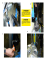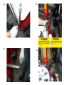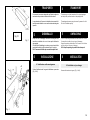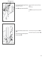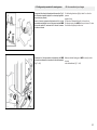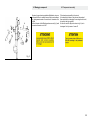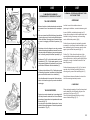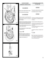
1
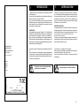
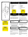
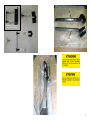
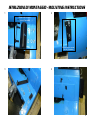
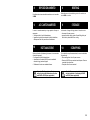
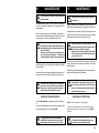
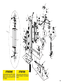
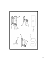
HP2
MANUALE DI ISTRUZIONI PER L'USO E
LA MANUTENZIONE
Istruzioni originali
USE AND MAINTENANCE INSTRUCTIONS
Original instructions
Cod. 3019950
ED. 01/11
DICHIARAZIONE CE DI CONFORMITA'
CE DECLARATION OF CONFORMITY
DECLARATION DE CONFORMITE CE
CE - ÜBEREINSTIMMUNG
DECLARACION CE DE CONFORMIDAD
TAG s.r.l. Via Modena, 38 - 42015
Correggio (RE) Italy
dichiara sotto la propria esclusiva responsabilità che il prodotto:
declare on our own responsibility that the product:
Déclare sous son propre responsabilité que le produit:
erklärt unter ihrer eigenen Verantwortung, daß das Erzeugnis:
Declara bajo su responsabilidad que el producto:
Accessorio pneumatico per smontagomme auto
Accessoire pneumatique pour démonte-pneus voiture
Pneumatic accessory for car tyre-changer
Druckluftzubehör für PKW-Montiermaschine
Spazio per targhetta
al quale questa dichiarazione si riferisce E' CONFORME ALLE SEGUENTI DIRETTIVE:
to which declaration refers is in conformity with the FOLLOWING DIRECTIVES:
au quel cette déclaration se rapporte EST CONFORME AUX DIRECTIVES SUIVANTES:
darauf diese Erklärung Bezug nimmt, mit den folgenden Bestimmungen übereinstimmt:
2006/42/CE - 91/368/CEE - 93/68/CEE - 2006/95/CE - 2004/108/CE
ed alle Norme:
as well as to the following norms:
ainsi qu’aux normes suivantes:
und folgender Vorschrift gemäß:
EN 12100
Il firmatario della presente dichiarazione è la persona autorizzata a costituire il fascicolo tecnico
The signer of this declaration of conformity is the person authorized to provide for the technical file literature
Le signataire de cette déclaration de conformité est la personne autorisée à produire le dossier technique
Der Unterzeichner dieser CE-Übereinstimmung ist dazu ermächtigt, das technische Aktenbündel vorzulegen
El firmante de esta declaración es la persona autorizada para elaborar el expediente técnico
Correggio, 10/01/2011
Il modello della presente dichiarazione è conforme alla Norma EN ISO/IEC 17050-1
The model of present declaration is in conformity with directive EN ISO/IEC 17050-1
Le modèle de cette déclaration est conforme à la Norme EN ISO/IEC 17050-1
Das Modell dieser Erklärung übereinstimmt mit der Bestimmung EN ISO/IEC 17050-1
El modelo de esta afirmación está en consonancia con la norma EN ISO/IEC 17050-1
L'Amministratore Unico
TAG S.r.L
SOMMARIO
INDEX
1 - INTRODUZIONE
1 - INTRODUCTION
.............................................................4
2 - DESCRIZIONE DELLA MACCHINA
2 - DESCRIPTION OF THE MACHINE
.............................................................5
3 - GENERALITA'
3 - GENERALS
.............................................................5
4 - TRASPORTO
4 - TRANSPORT
.............................................................19
5 - DISIMBALLO
5 - UNPACKING
.............................................................19
6 - INSTALLAZIONE
6 - INSTALLATION
.............................................................19
.......................................................19
.......................................................21
6.1 Installazione sullo smontagomme
6.2 Collegamenti pneumatici allo
smontag.
6.3 - Montaggio componenti
6.1 Installation on tyre-changer
6.2 Air connection to tyre-changer
6.3 Components assembly
7 - USO
7 - USE
7.1 Removal Tyres
7.2 Mounting Tyres
.......................................................22
.............................................................23
.......................................................23
.......................................................24
8-RIPOSIZIONAMENTO
8- RESITING
.............................................................25
9-ACCANTONAMENTO
9- STORAGE
.............................................................25
10-ROTTAMAZIONE
10- SCRAPPING
.............................................................25
11-MANUTENZIONE
11- MAINTENANCE
.............................................................26
12-RICAMBI
12-SPARE PARTS
.............................................................27
7.1 - Smontaggio pneumatici
7.2 - Montaggio pneumatici
1
INTRODUZIONE
Vi ringraziamo per aver acquistato un prodotto della Nostra
linea di accessori.
La macchina è realizzata attraverso l’applicazione dei migliori
principi in rispetto al concetto di qualità.
Per un corretto funzionamento e per una lunga durata sarà
sufficiente osservare le semplici istruzioni contenute nel presente manuale che dovrà essere letto e compreso nel modo
più completo in ogni sua parte.
ANAGRAFICA
Una completa descrizione del “Modello” e il “N.ro di Matricola”
faciliterà il servizio della Nostra assistenza e la spedizione di
parti di ricambio. Per maggiore chiarezza e comodità ricordiamo i dati del Vostra attrezzatura nel riquadro sottostante.
Qualora vi fossero delle discordanze fra i dati riportati nel presente manuale e quelli sulla targhetta applicata alla macchina,
faranno fede quelli sulla targhetta.
Casa costruttrice:
Manufactured by:
Maison constructrice:
Herstellerfirma:
Empresa fabricante:
Indirizzo:
Address:
Adresse:
Adresse:
Dirección:
Il presente manuale costituisce parte integrante del prodotto.
Prima di utilizzare lo smontagomme, leggere attentamente
le avvertenze e le istruzioni contenute nel presente libretto in
quanto forniscono importanti indicazioni riguardanti la sicurezza d’uso e la manutenzione.
Conservare con cura questo manuale per
ogni ulteriore consultazione
1
INTRODUCTION
Thank you for purchasing a product from the line of accessories. The machine has been manufactured in accordance with
the very best quality principles. Follow the simple instructions
provided in this manual to ensure the correct operation and
long life of the machine. Read the entire manual thoroughly
and make sure you understand it.
IDENTIFICATION DATA
A complete description of the “Model” and the “Serial number”
will make it easier for our technical assistance to provide service
and will facilitate delivery of any required spare parts. For clarity
and convenience, we have inserted the data of the
equipment in the box below.
If there is any discrepancy between the data provided in this
manual and that shown on the plate fixed to the machine, the
latter should be taken as correct.
This manual is an integral part of the product.
Before using the tyre changer, read carefully the warnings and
instructions contained in this manual since
they provide important information on operating safety and
maintenance.
Keep this manual for further reference.
4
2
HP 2
1
2
3
1)
2)
3)
4)
5)
6)
7)
8)
DESCRIZIONE DELLA MACCHINA
Braccio 1
Comando azionamento salita/discesa
Braccio premitallone
Utensile premitallone
Disco alzatalloni
Braccio disco
Utensile a disco
Utensile a rullo
6
8
7
4
5
Fig. 1
3
GENERALITA'
2
1)
2)
3)
4)
5)
6)
7)
8)
3
DESCRIPTION OF THE MACHINE
Arm 1
Lifting/lowering control
Bear pressing arm
Bead pressing tool
Bead lifting disk
Operating arm with bead lifting disk
Disk tool
Roller tool
GENERALS
3.1 DESTINAZIONE D’USO.
3.1 INTENDED USE
L'accessorio è stato progettato e realizzato esclusivamente per
essere montato su smontagomme automatici, per agevolare
lo smontaggio e il montaggio dei pneumatici dai/sui cerchi.
This accessory has been designed and manufactured
exclusively for being installed on automatic tyre-changers
inorder to facilitate removing and mounting of tyres from/
onto the rims.
Any other use is to be considered incorrect and
unreasonable.
Qualsiasi altro uso è da considerarsi improprio
quindi irragionevole
In particolare il costruttore non può essere considerato
responsabile per eventuali danni causati da usi non esplicati
in questo manuale e quindi impropri, erronei ed irragionevoli.
3.2 NORME GENERALI DI SICUREZZA.
L’uso delle attrezzature è consentito solo ed
esclusivamente a personale esperto, appositamente addestrato ed autorizzato.
Ogni e qualsiasi manomissione o modifica dell’apparecchiatura
non preventivamente autorizzate dal costruttore, sollevano
quest’ultimo da ogni responsabilità per danni derivati o riferibili
agli atti suddetti.
La rimozione o manomissione dei dispositivi di sicurezza comporta la decadenza immediata della garanzia e la violazione
delle Norme Europee per la Sicurezza.
In particular the manufacturer cannot be held responsible for
any damage caused throught the use for purposes other
than those specified in this manual, and therefore inappropriate, incorrect and unreasonable.
3.2 GENERAL SAFETY RULES
The use of these accessories is permitted
only and exclusively to trained and authorized
expert staff.
Any tampering or modification to the equipment carried out
without the manufacturer's prior authorization will free him
from all responsibility for damage caused directly or indirectly by the above actions.
Removing or tampering with safety devices immediately invalidates the warranty and it is in contravention of European
Safety Standards.
5
Contenuto del Kit - Kit outfit
6
7
Utilizzare solo se occorre Use only if necessary
8
7
ISTRUZIONI DI MONTAGGIO - MOUNTING INSTRUCTIONS
1
2
Utilizzare solo se occorre Use only if necessary
Utilizzare solo se occorre Use only if necessary
3
4
8
5
6
7
8
9
9
10
12
11
10
13
14
15
11
16
17
18
19
12
20
21
22
23
13
24
26
25
27
14
28
29
30
31
15
32
33
34
16
35
36
38
37
17
35a
37a
36a
38a
18
370
4
145
0
100
0
TRASPORTO
4
TRANSPORT
L'accessorio deve essere trasportato nell'imballo originale e
mantenuto nella posizione indicata sull'imballo stesso.
The accessory must be transported in its original package
and kept in the position shown on the package itself.
Lo spostamento dell' accessorio imballato deve essere effettuato inforcando l'imballo con un carrello elevatore di adeguate
capacità.
The packaged accessory may be moved by means of a fork
lift truck of suitable capacity.
410
5
Kg. 81
Fig. 2
Dopo aver tolto l'imballaggio assicurarsi dell'integrità della
macchina controllando che non vi siano parti visibilmente
danneggiate.
Gli elementi dell'imballaggio non devono essere lasciati alla
portata dei bambini in quanto potenziali fonti di pericolo.
N.B.: Conservare l'imballo per eventuali trasporti futuri.
6
A
DISIMBALLO
INSTALLAZIONE
6.1 Installazione sullo smontagomme
Svitare il lubrificatore ed il supporto lubrificatore se presente
(Fig. 3 rif.A)
5
UNPACKING
Once the packing material has been removed, check
the machine visually for any signs of damage.
Keep the packing materials out of the reach of children
as they can be a source of danger.
N.B.: Keep the packing for possible future transport.
6
INSTALLATION
6.1 Installation on tyre-changer
Unscrew lubricator and support (Fig. 3 ref.A).
Fig. 3
19
Utilizzare solo se occorre
D
E
Inserire negli appositi fori le piastrine di supporto (D) e fissarle
col dado basso M10 come in fig. 4
Montare l' HP 2 sui supporti e fissarlo tramite i dadi M10 (E)
E
D
Set the support plates (D) in relevant holes and fix them by
means of
low nut M10 (Fig.4)
Mount HP2 onto the supports and fix it by means of nuts M10
(E)
E
Fig. 4
Avvitare il supporto lubrificatore (se presente) alla carcassa
di HP 2
Fissare il lubrificatore al supporto (se presente) oppure direttamente alla carcassa di HP 2.
Fix the lubricator support (if any) by screws to the HP2 body.
Fix the lubricator to the support (if any) or directly to the HP2.
Fig. 5
20
6.2 Collegamenti pneumatici allo smontagomme.
6.2 Air connection to tyre-changer
Recuperare il tubo rilsan di alimentazione della macchina (Fig. 6)
ed, utilizzando un taglia tubi, tagliarlo 5 cm circa dopo il regolatore
di pressione (se presente).
Inserire il raccordo, presente nella dotazione del kit, nel tubo
precedentemente tagliato. Inserire il tubo proveniente dall'HP2
nel raccordo rapido di 6, assicurarsi che il tubo entri in manera
corretta nel raccordo.
Cut the feeding rilsan hose (fig.6) at about 5 cm. from the
pressure
regulator (if any).
Set the union, delivered with the kit, into the cut hose.
Set the pipe coming from HP2 into the quick union of 6, make
Sure the hose fit properly into the union.
Assicurarsi che il tubo pneumatico di alimentazione dell' HP2
sia inserito correttamente nel raccordo al di sotto del basamento
(Fig. 7, rif. A)
Make sure that the feeding pipe of HP2 is correctly set into
the union
under the baseframe (Fig. 7, ref.A)
Fig. 6
Fig. 7
21
6.3 Montaggio componenti.
Montare il gruppo braccio premitallone H infilandolo nel perno,
utilizzando la vite e le rondelle I serrare il tutto in modo adeguato. Analogamente montare il braccio disco L fissandolo con le
viti M.
Infilare il braccio rullo N o R (nella posizione come in fig. 8) nella
sua sede e bloccarlo con le viti P.
I
H
Pr
Pn
6.3 Components assembly
Fit the bead pressing arm H into the pin and
fix it adequately by means of the screw and the washers I.
Same procedure must be applied for mounting the disk arm L;
this must be fixed by screws M.
Set the roller arm N or R (position shown in fig. 8) into its
housingand lock it by means of screws P.
R
N
M
L
Fig. 8
22
7
4
Fig. 12
Fig. 9
USO
Y
Fig. 10
Fig. 13
7.1-REMOVAL OF EXTRALOW PROFILED TYRES
OR "RACING"TYRES
TALLONE SUPERIORE
UPPER BEAD
Bloccare il cerchio sul piatto autocentrante come indicato
sul manuale d'uso e manutenzione dello smontagomme.
Nel caso si presentino difficoltà utilizzare il premitallone
(4)per tenere premuto il cerchio sulle griffe dell'autocentrante e facilitarne il bloccaggio (se necessario utilizzare
un cono di centraggio per facilitale l'operazione) (Fig.
9)
Lock the rim onto the turntable as shown in
tyrechanger’s installation, use and maintenance guide.
Posizionare (Fig.10) il rullo alla destra della torretta e il
premitallone (4) (Fig. 11) dalla parte opposta, in modo
che premano leggermente il pneumatico verso il basso,
per facilitare l'inserimento della leva alzatalloni (Y).
Posizionare il premitallone rif.4 fig.11 dalla parte opposta
all'utensile per agevolare il caricamento del tallone della
gomma sull'utensile usando la leva alzatalloni (Y)
Una volta abbassata la leva eportato il tallone del pneumatico sulla torretta seguire la procedura standard di
smontaggio.
TALLONE INFERIORE
4
Fig. 11
USE
7.1-SMONTAGGIO PNEUMATICI
ULTRARIBASSATI O CON PROFILO "RACING"
Posizionare la torretta integrale come da procedura
standard di smontaggio riportata sul manuale d'uso e manutenzione dello smontagomme (se necessario premere
con il rullo sulla gomma per facilitare l'operatore) fig. 8
Y
7
Seguire la procedura standard per lo smontaggio definitivo del pneumatico, aiutandosi con il disco alzatalloni
per sostenere il pneumatico in corrispondenza del canale
del cerchio (Fig.12).
In questo modo viene facilitato l'inserimento e il caricamento del tallone della gomma sull'utensile da parte della
leva alzatalloni Y (Fig.13).
In case of difficulty, use the bead-pressing tool (4)
to keep the rim pressed onto the turntable clamps and
facilitate its locking (if necessary, use the centering
cone to facilitate the operation) (fig.9)
Position the mounting head as indicated by standard
proceeding for tyre removal inside the installation, use
and maintenance guide (if necessary, press the roller
against tyre to facilitate the operation) (fig. 8)
Position (Fig. 10) the roller at the right side of the
mounting head and the bead-pressing tool (4) (fig.11)
at the opposite side, so that they press slightly the tyre
downwards, in order to facilitate introduction of the
bead lifting lever (Y).
Position the bead-pressing tool (4) (fig.11) at the tool
opposite side to facilitate tyre bead positioning on
mounting tool by means of the bead lifting lever (Y)
Once the lever is down and the bead is set onto the
tool follow removing standard procedure.
LOWER BEAD
Follow standard proceedings for tyre final removal and
use the bead-lifting disk for keeping the tyre at the
same level of rim’s groove (Fig.12))
This will facilitate tyre bead positioning on tool by
means of the bead-lifting (Fig. 13).
23
7.2 - MONTAGGIO PNEUMATICI
ULTRARIBASSATI O CON PROFILO "RACING"
7.2 - MOUNTING EXTRALOW PROFILED TYRES
OR "RACING"TYRES
TALLONE INFERIORE
LOWER BEAD
8
X
Seguire la procedura standard descritta sul manuale
di uso e manutenzione dello smontagomme
4
Fig. 13
Follow standard proceedings described in the Installation,
Use and Maintenance guide of Tyre-Changer.
TALLONE SUPERIORE
UPPER BEAD
Posizionare il pneumatico come descritto nella procedura
standard descritta sul manuale di uso e manutenzione
dello smontagomme
Position the tyre as described by standard proceedings
inside the Installation, Use and Maintenance guide of
Tyre-Changer.
Posizionare il rullo (8) e il premitallone (4) a destra della
torretta (X) in modo che il tallone superiore del pneumatico sia in corrispondenza del canale del cerchio (Fig.13).
Per regolare l'altezza del premitallone svitare o avvitare
la vite come in figura 10 pag. 9.
Position the roller (8) and the bead-pressing tool (4)
at the right side of the mounting head (X) in a way that
the tyre upper bead stays at the same level of rim’s
groove (Fig. 13)
To adjust the height of bead-pressing tool, screw down
or out as Per fig. 10, page 9.
Far ruotare l'autocentrante fino al completo montaggio
del pneumatico (Fig.14).
Disimpegnare l' HP2
N.B. Se durante l'operazione il premitallone (4) non
preme in modo adeguato (preme troppo o troppo
poco), occorre regolare la sua altezza avvitando o
svitando la vite come indicato in fig. 15
Let turntable turn until the tyre is completely mounted
(Fig.14).
Release HP2.
Note: if, during the operation, the bead-pressing tool
(4) is not pressing the tool adequately (too much or too
few), it is necessary to adjust its height by screwing
down or out the screw as per fig. 15.
Fig. 14
Fig. 15
24
8
RIPOSIZIONAMENTO
Fare riferimento al manuale della macchina su cui è montato
l' HP2.
9
ACCANTONAMENTO
In caso di accantonamento per lungo periodo di tempo è
necessario:
• Scollegare tutte le fonti di alimentazione
• Ingrassare le guide di scorrimento dei dischi alzatallone,
del tampone e del rullo per evitarne l'ossidazione
10
ROTTAMAZIONE
Qualora si decida di rottamare gli accessori, si raccomanda
di renderli inoperanti:
• Scollegando le fonti di alimentazione.
• Asportando tutti i materiali NON ferrosi e smaltendoli
secondo le leggi nazionali vigenti.
• Rottamando il resto come materiale ferroso.
Attenzione! Per il corretto smaltimento consultare le note sulla dichiarazione di conformità RAEE e ROHS (dove applicabile)
8
RESITING
Make reference to the Installation guide of the machine, on
which HP2 is installed.
9
STORAGE
In the event of storage for long periods of time, be sure to:
• disconnect all power sources.
• grease the clamp sliding guides of bead-lifting disks, pad
and roller to prevent them from oxiding.
10
SCRAPPING
If you decide to scrap the accessories, be sure to make them
inoperative by:
• Disconnecting them from all power sources.
•Remove all NON-ferrous materials and dispose of them as
prescribed by national law.
• Scrap the rest as ferrous material.
Attention! For a correct waste disposal, consult the declaration of conformity to RAEE
and ROHS (where applicable)
25
11
MANUTENZIONE
La manutenzione è sempre vietata a personale
non autorizzato
La manutenzione regolare, come da istruzioni, è fondamentale per un corretto funzionamento e una lunga durata dello
smontagomme
Se la manutenzione non viene effettuata regolarmente, il
funzionamento e l'affidabilità della macchina possono essere
compromesse, a rischio sia dell'operatore che di terzi.
Prima di effettuare qualsiasi intervento di manutenzione, disinserire l'allacciamento elettrico,
scollegando la spina, e quello pneumatico chiudendo il rubinetto.
Inoltre, per scaricare l'aria in pressione dal circuito, è necessario effettuare 3 - 4 stallonature
a vuoto premendo il pedale sullo smontagomme.
Le parti difettose devono essere sostituite esclusivamente da
personale esperto e con pezzi originali indicati dal catalogo
parti di ricambio.
La rimozione o manomissione dei dispositivi di sicurezza comporta una violazione delle Norme Europee sulla Sicurezza.
In particolare il costruttore non è imputabile
per reclami derivanti dall'uso di ricambi non
originali o per danni causati dalla rimozione o
manomissione dei sistemi di sicurezza.
OPERAZIONI DI MANUTENZIONE:
Pulire settimanalmente e ingrassare le guide di scorrimento.
Per il resto, fare riferimento al manuale d'uso e manutenzione
dello smontagomme sui cui è montato l'HP2
Al raggiungimento dei 5 anni dalla data di
installazione e messa in servizio, il prodotto
dovrà essere revisionato in tutte le sue parti
11
MAINTENANCE
Unauthorized staff may not carry out maintenance work.
Regular maintenance as described in the instructions is essential for correct operation and a long lifetime of the machine.
If maintenance is not carried out regularly, the operation and
reliability of the machine may be compromised, thus placing
the operator and anyone else in the vicinity at risk.
Before carrying out any maintenance work,
disconnect the plug of electric supply and turn
off the tap for pneumatic supplies.
Moreover, it is necessary to break the bead loadless 3-4 times in order to let the air in pressure
go out of the circuit.
Defective parts must be replaced exclusively by expert staff
using the manufacturer's spare parts indicated in the spare
parts catalogue.
Removing or tampering with safety devices represents a contravention of European Safety Standards.
In particular the manufacturer shall not be held
responsible for complaints deriving from the
use of spare parts made by other manufacturers or for damage caused by tampering or
removal of safety systems.
MAINTENANCE OPERATIONS:
Weekly clean and grease the sliding guides.
For the rest, make reference to the Installation, Use and
Maintenance guide of the tyre-changer, on which HP2 is
mounted.
At the achievement of 5 years from the date
of installation and commissioning, the product must be reviewed in its entirety
26
PARTI DI RICAMBIO
SPARE PARTS
27
34
33
54
A
36
1
29
B
55
52
50
42
40
25
38
9
20
47
25
15
16
14
13
26
20
39
20
20
25
43
42
58
23
10
23
22
89
38
12
19
41
56
7
18
24
2
20
11
87
96
3
44
17
46
57
25
25
27
5
37
43
C
66
79
C
65
29
4
36
8
59
80
37
45
55
39
B
39
61
51
35
30
40
49
60
62
A
31
32
29
51
48
78
28
78
41
53
25
95
81
82
A
63
21
64
83
84
54
94
6
93
85
90
86
88
91
92
28
68
77 75
76
69
67
77 75
76
70
72
71
73
77
75
76
74
29
1
2119610
BASE HP2
HP2 POST
HP2 SAEULE
HP2 COLONNE
2
2119731
BRACCIO ESAG.SUPP.DISCO COMP
DISC HOLD ARM
BRAS SUPPORT DISQUE
SCHEIBETRAGARM
3
6619749
BRACCIO SUP. CURVO D.60 HP2
BENT ARM D.60
BRAS COURBE D.60
GEKRUEMMTER ARM D.60
4
6619750
BRACCIO DRITTO D.60 HP2
STRAIGHT ARM D.60
BRAS DROIT D.60
GERADER ARM D.60
5
6619751
BRACCIO DISCO HP2 INFERIORE
DISC HOLD ARM
BRAS SUPPORT DISQUE
SCHEIBETRAGARM
6
3019715
VOLANTINO M16 V1/70/V-M16X210(250)
HAND WHEEL M16 V1/70/V-M16X210(250) VOLANT M16 V1/70/V-M16X210(250)
HANDRAD M16 V1/70/V-M16X210(250)
7
3006886
DISCO STALLONATORE
BEAD BREAKING DISK
DISQUE DECOLLE-TALONS
WULSTABDRUECKPLATTE
8
6619617
CARRELLO ESTERNO HP2
OUTER CARRIAGE
CHARIOT EXTERIEUR
AUSSENSCHLITTEN
9
6619621
CARRELLO INTERNO HP2 - NERO
INNER CARRIAGE
CHARIOT INTERIEUR
INNENSCHLITTEN
10
3018464
DISCO "S" D. 150
DISC "S" D.150
DISQUE "S" D.150
SCHEIBE "S" D.150
11
3017440
PREMITALLONE P.A. BOSS
BEAD PRESSING TOOL
PRESSE TALON
WULSTDRUECKER
12
3019748
VITE TAMPONE HP2
SCREW
VIS
SCHRAUBE
13
4293924
VOLANTINO THP D.50 M12 L=50
HAND WHEEL THP D.50 M12 L=50
VOLANT THP D.50 M12 L=50
HANDRAD THP D.50 M12 L=50
14
2012683
GR.IMPUGNATURA+VITE STEI M10
HANDLE+SCREW
POIGNEE+VIS
HANDGRIFF+SCHRAUBE
15
3010283
IMPUGNATURA D.25 M10 ZINC. B.
HANDLE D.25 M10
POIGNEE D.25 M10
HANDGRIFF D.25 M10
16
4398284
VITE STEI 10x30 P.P.
SCREW 10x30
VIS 10X30
SCHRAUBE 10x30
17
4395669
RONDELLA 10 (11x40x2,5)ZNT6592
WASHER 10 (11x40x2,5)
RONDELLE 10 (11x40x2,5)
BEILAGSSCHEIBE 10 (11x40x2,5)
18
3006862
PERNO SUP.DISCO ST.BRUNITO
DISK PIN
AXE DISQUE
PLATTENSTIFT
5923
19
4399378
RONDELLA 10 (10,5x21x2)ZNT6592
WASHER D.10 (10,5x21x2)
RONDELLE D.10 (10,5x21x2)
BEILAGSSCHEIBE 10 (10,5x21x2)
20
4393900
VITE TCEI 10x30 8.8 ZNT 5931
SCREW TCEI 10x30 8.8
VIS TCEI 10x30 8.8 ZNT 5931
SCHRAUBE TCEI 10x30 8.8
21
4395235
VITE TBEI 12x25 10.9 UBK ZNT
SCREW TBEI 12x25 10.9 UBK
VIS TBEI 12x25 10.9 UBK
SCHRAUBE TBEI 12x25 10.9 UBK
22
3019734
PERNO ATTACCO DISCO - BRUNITO
DISC PIN
AXE DISQUE
SCHEIBENSTIFT
23
4294264
CUSCINETTO 6004 2RS 20-42-12
BEARING 6004 2RS 20-42-12
COUSSINET 6004 2RS 20-42-12
LAGER 6004 2RS 20-42-12
24
4397615
VITE TSPEI M12X25 10.9 ZNT 5933
SCREW 12x25
VIS 12X25
SCHRAUBE 12x25
25
4296944
CUSCINETTO RULLI CONICI 30204
BEARING
COUSSINET
UNTERLAGE
26
4393902
VITE TCEI 20x160 12.9 5739
SCREW TCEI 20x160 12.9
VIS TCEI 20x160 12.9
SCHRAUBE TCEI 20x160 12.9
27
4399813
RONDELLA 20 (21x37x3) ZNT 6592
WASHER 20 (21x37x3)
RONDELLE 20 (21x37x3)
BEILAGSSCHEIBE 20 (21x37x3)
28
2019757
GR.VALVOLA HP2
VALVE UNIT
GR. CLAPET
VENTIL
29
4198618
RACCORDO 6522 1/8"-6 (90°-GIR.+ OR)
UNION 1/8"
RACCORD 1/8"
ANSCHLUSS 1/8"
30
4198285
VALVOLA 5 VIE 228-53-31-9-1/2
5-WAY VALVE
SOUPAPE A'' 5 VOIES
FUENFWEGEVENTIL
31
4399897
VITE TE 4x25 8.8 PF ZNT 5737
SCREW 4x25
VIS 4x25
SCHRAUBE 4x25
32
4199610
SILENZIATORE 1 SFE 1/8" OTTONE C/RETE
SILENCER 1/8"
SILENCIEUX 1/8"
SCHALLDAEMPFER 1/8"
33
3010284
POMOLO D.14x45 FORO M5 ZNT
KNOB D.14X45 M5
POMMEAU D.14x45 M5
KUGELGRIFF D.14x45 M5
34
3019779
CARENATURA ABS HP2 NERO
ABS FRAME
COUVERTURE EN ABS
ABS ABDECKUNG
35
4399828
RONDELLA 16 (17x30x3) ZNT 6592
WASHER 16 (17x30x3)
RONDELLE 16 (17x30x3)
BEILAGSSCHEIBE 16 (17x30x3)
36
4393899
VITE TE 20X120 8.8 P.F. ZNT 5737
VITE TE 20X120 8.8 P.F.
VIS TE 20X120 8.8 P.F.
SCHRAUBE TE 20X120 8.8 P.F.
30
37
4399967
DADO M10 6S BASSO ZNT
5589
38
4399971
DADO AUTOBL.M10 BASSO.6S. 7474
NUT M10
ECROU M10
MUTTER M10
SELF-LOCKING NUT M10
ECROU DE VERROUILLAGE M10
SELBSTSICHERNDE MUTTER M10
39
4394164
DADO AUTOBL.M20 BASSO H.20 7474
SELF-LOCKING NUT M20 LOW H.20
ECROU DE SECURITE` M20 H.20
SELBSTSICHERNDE MUTTER M20 H.20
40
3019627
PATTINO HP 2
SLIDING BLOCK
PATIN
GLEITSCHUH
41
3000599
PERNO X CROC. M12 L=50 TCEI (12.9)
PIN M12 L=50
AXE M12 L=50
STIFT M12 L=50
42
4399865
DADO AUTOBL.M12 BASSO.6S. 7474
SELF-LOCKING NUT M12
ECROU DE VERROUILLAGE M12
SELBSTSICHERNDE MUTTER M12
43
4393900
VITE TCEI 10x30 8.8 ZNT 5931
SCREW TCEI 10x30 8.8
VIS TCEI 10x30 8.8
SCHRAUBE TCEI 10x30
44
4395556
DADO M12 MEDIO
NUT M12
ECROU M12
MUTTER M12
45
2019628
GR. CILINDRO D.90 HP 2
CYLINDER UNIT D.90
GR. VERIN D.90
ZYLINDER D.90
46
3019629
CAMICIA CIL. D.90 L=510,5
CYLINDER LINER D.90 L=510,5
CHEMISE VERIN D.90 L=510,5
ZYLINDERMANTEL D.90 L=510,5
ZNT
5588
47
3019631
VITE SPECIALE TE M8x543 ZNT B.
SPECIAL SCREW TE M8x543
VIS SPECIALE TE M8x543
SONDERSCHRAUBE TE M8x543
48
3199601
ANELLO RASCH.BID.L7 NSW 20 30 6/CO
SCRAPER
SEGMENT RACLEUR
KRATZSCHEIBE
49
4398146
RASAMENTO 24x30x1
STEEL SHIM 24x30x1
CALE EN ACIER 24x30x1
STAHLZWISCHENLAGE 24x30x1
50
3199599
ANELLO SEEGER I D.30 JV
SEEGER RING D.30
BAGUE SEEGER D.30
SEEGER-RING D.30
51
4293965
ANELLO OR 3325 82,22X2,62
ORING 3325 82,22X2,62
JOINT TORIQUE 3325 82,22X2,62
ORING 3325 82,22X2,62
52
3019632
FLANGIA ANT. CILINDRO D.90 - ZNT
CYLINDER FRONT FLANGE
FLASQUE AVANT VERIN
ZYLINDERVORDERFLANSCH
53
4394721
ANELLO SEEGER E D.36 7435
SEEGER RING D.36 7435
JOINT SEEGER D.36 7435
SEEGER RING D.36 7435
54
4399900
DADO AUTOBL.M 8 BASSO 6.S 7474
SELF-LOCKING NUT M8
ECROU DE VERROUILLAGE M8
SELBSTSPERRENDE MUTTER M8
55
4198921
COLONNETTA M/F 1/8" 2525 H=16
STUD BOLT 1/8" H=16
COLONNETTE 1/8" H=16
BUNDSCHRAUBE 1/8" H=16
56
2119633
FLANGIA POSTERIORE CIL. D.90-ZNT
CYLINDER BACK FLANGE
FLASQUE ARRIERE VERIN
ZYLINDERHINTERFLANSCH
57
4399865
DADO AUTOBL.M12 BASSO.6S. 7474
SELF-LOCKING NUT M12
ECROU DE VERROUILLAGE M12
SELBSTSICHERNDE MUTTER M12
58
4193964
PISTONE MONOBLOCCO TDUOP D.90
PISTON D.90
PISTON D.90
KOLBEN D.90
59
3006649
ASTA CIL. HELP 2/3 L=561
CYLINDER ROD L=561
TIGE VERIN L=561
ZYLINDERSTANGE L=561
60
4294713
ANELLO OR 3150 37,77x2,62
ORING 3150 37,77x2,62
JOINT TORIQUE 3150 37,77x2,62
ORING 3150 37,77x2,62
61
4299168
ANELLO OR 3081 D.20,29x2,62
O-RING 20,29x2,62
JOINT OR D.20,29x2,62
O-RING 20,29X2,62ù
62
3017346
BOCCOLA GUARNIZIONI
SEALS BUSH
DOUILLE DE JOINTS
DICHTUNGSBUECHSE
63
4399863
RONDELLA 8 (9x24x2) ZNT 6593
WASHER 8 (9x24x2)
RONDELLE 8 (9x24x2)
BEILAGSSCHEIBE 8 (9x24x2)
64
4399954
VITE TCEI M 8x20 8.8 ZNT 5931
SCREW 8x20
VIS 8x20
SCHRAUBE 8x20
65
3019932
PIASTR.ESAG.RIPRESA GIOCO - ZNT
HEX. PLATE
PLAQUE HEXAG.
SECHSKANTPLATTE
66
3019934
RONDELLA SPECIALE HP2
SPECIAL WASHER
RONDELLE SPECIALE
SONDERSCHEIBE
67
2110301
CAVALLOTTO FISS. H3 S113-BRUN.
U BOLT
CRAMPILLON
KRAMPE
68
6619832
STAFFA SUP.POST.HP2 - NERO
SUPPORT PLATE
PLAQUE DE SUPPORT
STUETZPLAETTCHEN
69
2108784
VITE ANTIROTAZIONE H.3-BRUN.
ANTIROTATION SCREW H.3
VIS ANTIROTATION H.3
DREHSICHERE SCHRAUBE H.3
70
3019834
SPESSORE POSTERIORE HP2 - BRUNIT.
BACK SPACER
CALE ARRIERE
HINTERABSTANDSSTUECK
71
3019833
SPESSORE ANTERIORE HP2 - BRUNIT.
FRONT SPACER
CALE AVANT
VORDERABSTANDSSTUECK
72
2108782
CAVALLOTTO FISSAGGIO H.3-BRUN.
U BOLT
CRAMPILLON
KRAMPE
31
73
4198172
RACCORDO 6463 1/8"-6
UNION 1/8"
RACCORD 1/8"
ANSCHLUSS 1/8"
74
4198778
RACCORDO 6410 1/8"-8 S.RAPIDO
6410 QUICK UNION 1/8"-8
RACCORD 6410 1/8" -8 RAPIDE
SCHNELLANSCHLUSS 1/8"-8
75
4398662
ROND.GROWER D.10 ZNT
76
4399969
DADO M10 6S ALTO ZNT
77
4399378
78
3019760
1751
GROWER WASHER D.10
RONDELLE GROWER D.10
BEILAGSSCHEIBE GROWER D.10
NUT M10
ECROU M10
MUTTER M10
RONDELLA 10 (10,5x21x2)ZNT6592
WASHER D.10 (10,5x21x2)
RONDELLE D.10 (10,5x21x2)
BEILAGSSCHEIBE 10 (10,5x21x2)
TUBO ELASTOLAN 6X4 NERO L=3000
HOSE 6x4 L=3000
TUYAU 6x4 L=3000
SCHLAUCH 6x4 L=3000
5587
79
3019759
TUBO ELASTOLAN 6X4 BLU L=1450
HOSE 6x4 L=1450
TUYAU 6x4 L=1450
SCHLAUCH 6x4 L=1450
80
3019758
TUBO ELASTOLAN 6X4 BIANCO L=1050
HOSE 6x4 L=1050
TUYAU 6x4 L=1050
SCHLAUCH 6x4 L=1050
81
4399966
VITE TE 10x20 8.8
SCREW 10x20
VIS 10x20
SCHRAUBE 10x20
82
3002311
RONDELLA D.10,5x45x4
WASHER D.10,5x45x4
RONDELLE D.10,5x45x4
BEILAGSSCHEIBE D.10,5x45x4
83
2130632
BRACCIO ESAG.SUPP.RULLO HP2
ROLLER ARM
GR. BRAS ROULEAU
ROLLE UND ARM
84
4399810
DADO M20 6S BASSO
NUT M20
ECROU M20
MUTTER M20
85
3008433
RULLO ST.D.100 L120 NYLON NERO
ROLLER D.102 L=120
GALET D.102 L=120
ROLLE D.102 L=120
86
4397454
VITE TCEI M20x90 8.8
SCREW 20x90
VIS 20x90
SCHRAUBE 20x90
87
2030670
GR. BRACCIO DISCO X HP 2
DISC ARM UNIT X HP2
GR. BRAS DISQUE X HP2
SCHEIBE UND ARM X HP2
88
2030671
GR. BRACCIO RULLO X HP 2
ROLLER ARM UNIT X HP2
GR. BRAS ROULEAU X HP2
ROLLE UND ARM X HP2
89
4398414
VITE TCEI M10x16 8.8
SCREW 10x16
VIS 10x16
SCHRAUBE 10x16
90
6631224
LAMIERA SUPPORTO MANIGLIA - NERO
SUPPORT SHEET
SUPPORT CLAPET
STUETZBLECH
91
4297851
MANIGLIA A PONTE ABS PICCOLA
HANDLE
POIGNEE
HANDGRIFF
92
4399954
VITE TCEI M 8x20 8.8 ZNT 5931
SCREW 8x20
VIS 8x20
SCHRAUBE 8x20
93
4399829
RONDELLA 8 (8,4x16x1,5)ZNT6592
WASHER 8 (8,4x16x1,5)
RONDELLE 8 (8,4X16X1,5)
BEILAGSSCHEIBE 8 (8,4x16x1,5)
94
4399900
DADO AUTOBL.M 8 BASSO 6.S 7474
SELF-LOCKING NUT M8
ECROU DE VERROUILLAGE M8
SELBSTSPERRENDE MUTTER M8
95
4398631
VITE TE 12x50 8.8 ZNT 5739
SCREW 12x50
VIS 12x50
SCHRAUBE 12x50
96
4398657
DADO M12 BASSO ZNT 5589
NUT M12
ECROU M12
MUTTER M12
32