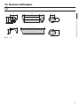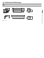
1
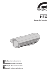
HEK
Aluminium and thermoplastic housing
EN English - Instructions manual
IT Italiano - Manuale di istruzioni
FR Francais - Manuel d'instructions
DE Deutsch - Bedienungslanleitung
HEK
Aluminium and thermoplastic housing
EN English - Instructions manual
Contents
ENGLISH
1.1 Typographical conventions................................................................................................................................. 5
2 Notes on copyright and information on trademarks................................................. 5
3 Safety rules.................................................................................................................... 5
4 Identification................................................................................................................. 6
4.1 Product description and type designation.................................................................................................... 6
4.2 Product markings.................................................................................................................................................... 6
5 Preparing the product for use...................................................................................... 6
5.1 Contents and unpacking...................................................................................................................................... 6
5.2 Safely disposing of packaging material.......................................................................................................... 6
6 Installing and assembling............................................................................................. 7
6.1 Installation................................................................................................................................................................. 7
6.1.1 How to open the housing.................................................................................................................................................... 7
6.1.2 How to install the camera.................................................................................................................................................... 7
6.1.3 How to install the heater...................................................................................................................................................... 7
6.1.4 How to install the blower..................................................................................................................................................... 8
6.1.4.1 12Vdc power supply.................................................................................................................................................................................... 9
6.1.4.2 24Vac power supply:................................................................................................................................................................................... 9
6.1.5 How to install the camera power supply........................................................................................................................ 9
7 Maintaining and cleaning........................................................................................... 10
7.1 Window and plastic cover cleaning (PC).......................................................................................................10
8 Disposal of waste materials........................................................................................ 10
9 Technical specifications.............................................................................................. 10
9.1 General......................................................................................................................................................................10
9.2 Mechanical...............................................................................................................................................................10
9.3 Electrical...................................................................................................................................................................10
9.4 Environment............................................................................................................................................................10
9.5 Compliance to........................................................................................................................................................10
10 Technical drawings.................................................................................................... 11
3
EN - English - Instructions manual
1 About this manual......................................................................................................... 5
4
EN - English - Instructions manual
3 Safety rules
Before installing and using this unit,
please read this manual carefully. Be sure
to keep it handy for later reference.
hh
1.1 Typographical conventions
DANGER!
High level hazard.
Risk of electric shock; disconnect the
power supply before proceeding with any
operation, unless indicated otherwise.
gg
WARNING!
Medium level hazard.
This operation is very important for
the system to function properly. Please
read the procedure described very
carefully and carry it out as instructed.
hh
INFO
Description of system specifications.
We recommend reading this part
carefully in order to understand
the subsequent stages.
jj
The manufacturer declines all responsibility
for any damage caused by an improper use
of the appliances mentioned in this manual.
Furthermore, the manufacturer reserves
the right to modify its contents without
any prior notice. The documentation
contained in this manual has been
collected with great care, the manufacturer,
however, cannot take any liability for
its use. The same thing can be said for
any person or company involved in the
creation and production of this manual.
• The device must be installed only and
exclusively by qualified technical personnel.
• Before any technical work on the appliance,
disconnect the power supply.
• Do not use power supply cables
that seem worn or old.
• Never, under any circumstances, make any
changes or connections that are not shown in
this handbook: improper use of the appliance
can cause serious hazards, risking the safety
of personnel and of the installation.
2 Notes on copyright and
information on trademarks
• Use only original spare parts. Nonoriginal spare parts could cause fire,
electrical discharge or other hazards.
The quoted names of products or companies
are trademarks or registered trademarks.
• Before proceeding with installation check
the supplied material to make sure it
corresponds with the order specification:
examine the identification labels, as described
in the section on "Product markings".
5
EN - English - Instructions manual
1 About this manual
EN - English - Instructions manual
4 Identification
4.1 Product description
and type designation
Innovative weatherproof housing for indoor/outdoor
installations. Made of extruded aluminium and plastic
material, it is provided with an innovative opening
system which allows access to the housing’s interior;
the body and the sunshield slide forward and hang
in place, while the unit remains fixed allowing access
to the camera from all angles. Its dimensions make
it suitable for CCD cameras equipped with fixed
lenses. Sturdy construction at a light weight, HEK
has two mounting options at the same time: regular
(WBMA) or feed-through (WBOVA2) bracket.
Its weatherproof features are ensured by EPDMrubber gaskets and by 3 M16 metric cable glands
or by the sealing gaskets, when installed with
bracket with internal cable management. A
wide range of accessories is available, including
sunshield, heater and fan-assisted heater, blower
and camera power supply. Further, it is also possible
to install a blower including an air filter replacing
one of the cable glands (not suitable in case of
using the bracket with internal cable channel).
The accessories are supplied factory
installed or as simple upgrade kit.
The innovative concept allows the installation in
different environments, either outdoor or indoor.
4.2 Product markings
See the label attached to the outside of the package.
5 Preparing the
product for use
Any change that is not expressly
approved by the manufacturer
will invalidate the guarantee.
hh
5.1 Contents and unpacking
When the product is delivered, make sure that
the package is intact and that there are no
signs that it has been dropped or scratched.
If there are obvious signs of damage,
contact the supplier immediately.
Keep the packaging in case you need
to send the product for repairs.
Check the contents to make sure they correspond
with the list of materials as below:
• Housing
• Housing equipment:
• Screws for camera
• Spacers
• Allen wrench
• Desiccant salt bag
• Instructions manual
5.2 Safely disposing of
packaging material
The packaging material can all be recycled.
The installer technician will be responsible for
separating the material for disposal, and in
any case for compliance with the legislation
in force where the device is to be used.
Bear in mind that if the material has to be returned
due to a fault, using the original packaging
for its transport is strongly recommended.
6
6 Installing and assembling
hh
6.1 Installation
Turn off the power before performing
any kind of operation.
gg
6.1.1 How to open the housing
This chapter describes how to install the camera
into the housing. We wish to remind our customers
that power supply can be drawn from the power
supply or heating circuit, if available, after
checking that the right supply voltage is used.
EN - English - Instructions manual
Only specialised personnel should be
allowed to install and assemble the device.
6.1.2 How to install the camera
Remove the body as described in
paragraph How to open the housing.
Move the internal slide sideways
to enter its lower part.
To open the housing (Fig. 01) unscrew the 2
screws (01) placed on the side in the middle of
the rear cover plate, take the body out (02), hang
it (Fig. 02) onto the suitable holder and leave the
internal and external slides in the working position.
Before closing the housing take off the protective
nylon and put silicagel salts envelope into.
01
02
Fig. 03
Put the insulating washer (01) between the 1/4”
screw (02) and the lower part of the slide, set the
insulating spacer (03) between the camera and
the upper part of the slide, tighten the 1/4” screw
and position the camera wherever wished.
Fig. 01
03
02
01
Fig. 02
Fig. 04
If necessary use the additional spacers for a proper
positioning of the camera and of the zoom lens.
Re-set the slide in the working
position and close the housing.
6.1.3 How to install the heater
This chapter describes how to install the heater
kit option in the dustproof housings that are not
equipped with it. The power input of the heater
kit can be 115/230Vac or 12Vdc/24Vac versions.
Its functioning is controlled by thermostat.
Remove the body as described in
paragraph How to open the housing.
7
EN - English - Instructions manual
Rotate the internal slide in order to
allow access to its lower part.
IN 115/230Vac
Fix the PTC element (01), by means of the
relevant plate (02), on the lowest part of the
internal slide. Run the wires along the channel
provided and through the hole (03).
02
01
03
Camera OUT
115/230Vac
Fig. 05
Fix the printed circuit with the supplied screws on the
slide’s pre-arranged studs near the rear cover plate.
Heater OUT
115/230Vac
Fig. 08
Blower OUT
24Vdc
Heater OUT
24Vac
OUT 24Vac
Fig. 06
Connect the wires of the heating element to the
circuit on the terminals marked with HEATER
(Fig. 07, 08, 09 and 10). There is also the possibility
of drawing the power for a camera; in this case,
note that the camera and the heater will be
fed from the same voltage and frequency.
IN 24Vac
Fig. 09
IN 100-240Vac
Connect the main supply wiring to the inlet terminals.
The standard version housings (without heater,
blower, etc.) feature ground connections, which
may be used to comply with local electrical
regulations or legislation (Fig. 07 and 09).
Camera OUT
12Vdc/24Vac
IN 12Vdc/24Vac
Heater OUT
100-240Vac
Fig. 10
Fit the slide in the working position
and close the housing.
6.1.4 How to install the blower
Camera OUT
12Vdc/24Vac
Fig. 07
8
Heater OUT
12Vdc/24Vac
This chapter describes how to install the
blower kit option into the housings that are not
equipped with it. The power input of the blower
kit can be 12Vdc or 24Vac. We wish to remind
our customer that the blower kit option can be
mounted together with the heater kit only if the
power input of the latter is 12Vdc or 24Vac.
6.1.5 How to install the
camera power supply
6.1.4.1 12Vdc power supply
Remove the body as described in
paragraph How to open the housing.
02
This chapter describes how to install the camera
power supply option into the housing.
EN - English - Instructions manual
Fix the blower kit on the rear cover (01) using the
supplied screws (02) with the air flow towards
the interior. We wish to remind that normally the
rear cover, provided for blower kit, are supplied
with a filter for the air intake which replaces
one of the 3 equipped M16 cable glands.
The camera power supply has an input voltage
of 100-240Vac and an output voltage of
12Vdc, 1A or an input voltage of 115/230Vac
and an output voltage of 24Vac, 400mA.
01
Fig. 12
IN 100-240Vac - OUT 12Vdc
Fig. 13
IN 115/230Vac - OUT 24Vac
Fig. 11
Carry out the connections to a corresponding
source of power (if available, it will be possible
to draw it from the heating circuit terminals
responsible for supplying power to the camera).
Close the housing.
6.1.4.2 24Vac power supply:
Remove the body as described in
paragraph How to open the housing.
Carry out the connections between the
blower kit and the relevant circuit (Fig. 09).
Fix the blower kit on the rear cover (Fig. 11, 01)
using the supplied screws (Fig. 11, 02) with the air
flow towards the interior. We wish to remind that
normally the rear cover, provided for blower kit,
are supplied with a filter for the air intake which
replaces one of the 3 equipped M16 cable glands.
Fix the printed circuit on the slide’s pre-arranged
studs near the rear cover plate (Fig. 01, 03). Carry
out the connections of the circuit to the external
source of power 24Vac. The above circuit can also
control the PTC thanks to the thermostat assembled.
Remove the body as described in
paragraph How to open the housing.
Slide off the back of the housing. Replace the
standard electronic card with the kit (01) card
using the 2 fixing screws (02). Carry out the
connections on the new electronic board.
Insert the power supply (03) on the support bracket
(04). Fix the power supply and the bracket onto the
back of the housing using the screws supplied (05).
Fit the six-pole connector at the end of the
cable into its corresponding cable, marked
J2 on the support circuit (Fig. 09).
04
03
02
01
05
The dustproof housings are pre-arranged
for fixing possible ground connections to be
carried out in compliance with the legislation in
force. In the circuit there is also the possibility
of drawing power supply for a camera.
Fig. 14
Close the housing.
Close the housing and refit the screws.
If heating has been already arranged,
replace the current circuit with the new one.
hh
9
EN - English - Instructions manual
7 Maintaining and cleaning
9 Technical specifications
7.1 Window and plastic
cover cleaning (PC)
9.1 General
Surface dirt should be rinsed away with water and
then the window cleaned with a neutral soap diluted
with water, or specific products for spectacle lens
cleaning. These should be applied with a soft cloth.
Extruded aluminium body and external slide
Avoid ethyl alcohol, solvents,
hydrogenated hydrocarbide, strong
acid and alkali. Such products may
irreparably damage the surface.
hh
8 Disposal of waste
materials
This symbol mark and recycle system
are applied only to EU countries
and not applied to the countries
in the other area of the world.
nn
Your product is designed and manufactured
with high quality materials and components
which can be recycled and reused.
This symbol means that electrical and electronic
equipment, at their end-of-life, should be disposed
of separately from your household waste.
Please dispose of this equipment at your local
Community waste collection or Recycling centre.
In the European Union there are separate collection
systems for used electrical and electronic products.
Resistant technopolymer front and back cover, RAL7030
Epoxypolyester powder painting, RAL9002 colour
Stainless steel external screws
Supplied with instruction manual, desiccant bag,
accessories for camera and lens mounting
9.2 Mechanical
3 cable glands
PMMA window (BxH): Ø 72mm (2.8in)
Internal usable area (BxH): 82x62mm (3.2x2.4in)
Internal usable length without accessories
HEK26
260mm (10.2in)
HEK30
300mm (11.8in)
Internal usable length with heater and/or power supply
HEK26
190mm (7.5in)
HEK30
235mm (9.3in)
Internal usable length with heater and/or blower
HEK26
190mm (7.5in)
HEK30
235mm (9.3in)
9.3 Electrical
Heater Ton 15°C+/-3°C (59°F +/-5°F) Toff 22°C+/-3°C
(71°F +/-5°F)
-- IN 12Vdc/24Vac, consumption 20W max
-- IN 115/230Vac, consumption 40W max
Blower with thermostat air filter, Ton 35°C+/-3°C
(95°F+/-5°F) Toff 20°C+/-3°C (71°F+/-5°F) and back cover
-- IN 12Vdc, consumption 4W max
-- IN 24Vac, consumption 4W max
Not compatible with bracket with internal cable channel
Camera power supply
-- IN 100-240Vac - OUT 12Vdc, 50/60 Hz, 1A
-- IN 230Vac - OUT 24Vac, 50Hz, 400mA
9.4 Environment
Indoor / Outdoor
Operating temperature with heater: -20°C / +50°C
(-4°F / +122°F)
9.5 Compliance to
CE according to EN61000-6-3, EN 60065, EN50130-4
IP66 according to EN 60529 with cable glands
IP66 according to EN 60529 with special gasket and
bracket with internal cable channel
IP54 according to EN 60529 with bracket with internal
cable channel
10
10 Technical drawings
The values are in millimeters.
37
260 / 300
77.7
403 / 443
109
69.4
124.6
Fig. 15
73.7
62.2
101.5
109.5
123
EN - English - Instructions manual
jj
HEK
11
VIDEOTEC S.p.A.
www.videotec.com
Printed in Italy
MNVCHEKB_0839_EN
HEADQUARTERS ITALY
FRANCE
UK / IRELAND
U.S.A. / CANADA
ASIA PACIFIC
VIDEOTEC S.p.A.
Tel. +39 0445 697411
Fax +39 0445 697414
[email protected]
VIDEOTEC FRANCE S.A.R.L.
Tel. +33 2 32094900
Fax +33 2 32094901
[email protected]
VIDEOTEC UK SALES
Tel. +44 0113 815 0047
Fax +44 0113 815 0047
[email protected]
VIDEOTEC SECURITY, Inc.
Tel. +1 973 5950788
Fax +1 425 6484289
[email protected]
VIDEOTEC (HK) Ltd
Tel. +852 2333 0601
Fax +852 2311 0026
[email protected]
HEK
Custodia in alluminio e materiale termoplastico
IT Italiano - Manuale di istruzioni
Sommario
ITALIANO
1 Informazioni sul presente manuale............................................................................. 5
1.1 Convenzioni tipografiche..................................................................................................................................... 5
4.1 Descrizione e designazione del prodotto...................................................................................................... 6
4.2 Marcatura del prodotto......................................................................................................................................... 6
5 Preparazione del prodotto per l'utilizzo..................................................................... 6
5.1 Contenuto e disimballaggio................................................................................................................................ 6
5.2 Smaltimento in sicurezza dei materiali di imballaggio.............................................................................. 6
6 Installazione e assemblaggio....................................................................................... 7
6.1 Installazione.............................................................................................................................................................. 7
6.1.1 Apertura della custodia........................................................................................................................................................ 7
6.1.2 Installazione della telecamera............................................................................................................................................ 7
6.1.3 Installazione del riscaldamento......................................................................................................................................... 7
6.1.4 Installazione del ventilatore................................................................................................................................................ 8
6.1.4.1 Alimentazione 12Vdc.................................................................................................................................................................................. 9
6.1.4.2 Alimentazione 24Vac.................................................................................................................................................................................. 9
6.1.5 Installazione dell’alimentatore per telecamera............................................................................................................ 9
7 Manutenzione e pulizia.............................................................................................. 10
7.1 Pulizia del vetro e delle parti in plastica (PC)...............................................................................................10
8 Smaltimento dei rifiuti................................................................................................ 10
9 Dati tecnici................................................................................................................... 10
9.1 Generale...................................................................................................................................................................10
9.2 Meccanica................................................................................................................................................................10
9.3 Elettrico.....................................................................................................................................................................10
9.4 Ambiente..................................................................................................................................................................10
9.5 Conformità...............................................................................................................................................................10
10 Disegni tecnici........................................................................................................... 11
3
IT - Italiano - Manuale di istruzioni
2 Note sul copyright e informazioni sui marchi commerciali....................................... 5
3 Norme di sicurezza........................................................................................................ 5
4 Identificazione............................................................................................................... 6
4
IT - Italiano - Manuale di istruzioni
1 Informazioni sul
presente manuale
1.1 Convenzioni tipografiche
PERICOLO!
Pericolosità elevata.
Rischio di scosse elettriche. Togliere
l'alimentazione prima di procedere con
le operazioni, salvo diversa indicazione.
gg
ATTENZIONE!
Pericolosità media.
L'operazione è molto importante per
il corretto funzionamento del sistema.
Si prega di leggere attentamente
la procedura indicata e di eseguirla
secondo le modalità previste.
hh
INFO
Descrizione delle caratteristiche del
sistema.
Si consiglia di leggere attentamente
per comprendere le fasi successive.
jj
2 Note sul copyright
e informazioni sui
marchi commerciali
I nomi di prodotto o di aziende citati sono
marchi commerciali o marchi commerciali
registrati appartenenti alle rispettive società.
Il produttore declina ogni responsabilità
per eventuali danni derivanti da un
uso improprio delle apparecchiature
menzionate in questo manuale. Si
riserva inoltre il diritto di modificarne il
contenuto senza preavviso. Ogni cura é
stata posta nella raccolta e nella verifica
della documentazione contenuta in
questo manuale, tuttavia il produttore
non può assumersi alcuna responsabilità
derivante dall'utilizzo della stessa.
Lo stesso dicasi per ogni persona o
società coinvolta nella creazione e
nella produzione di questo manuale.
hh
IT - Italiano - Manuale di istruzioni
Prima di installare e utilizzare questa unità, leggere
attentamente questo manuale. Conservare questo
manuale a portata di mano come riferimento futuro.
3 Norme di sicurezza
• L'installazione e la manutenzione del
dispositivo deve essere eseguita solo
da personale tecnico qualificato.
• Prima di effettuare interventi tecnici
sull'apparecchio togliere l'alimentazione elettrica.
• Non utilizzare cavi di alimentazione con
segni di usura o invecchiamento.
• Non effettuare per nessun motivo
alterazioni o collegamenti non previsti in
questo manuale: l'uso di apparecchi non
idonei può portare a gravi pericoli per la
sicurezza del personale e dell'impianto.
• Utilizzare solo parti di ricambio originali. Pezzi
di ricambio non originali potrebbero causare
incendi, scariche elettriche o altri pericoli.
• Prima di procedere con l'installazione controllare
che il materiale fornito corrisponda alle
specifiche richieste, esaminando le etichette
di marcatura, secondo quanto descritto
nel capitolo Marcatura del prodotto.
5
4 Identificazione
IT - Italiano - Manuale di istruzioni
4.1 Descrizione e
designazione del prodotto
Costruita in estruso d’alluminio e materiale plastico,
è dotata di un sistema innovativo d’apertura
che permette un facile accesso al suo interno; il
corpo ed il tettuccio scorrono avanti rimanendo
attaccati alla parte anteriore della slitta esterna,
permettendo, così, l’accesso alla telecamera. Le
sue dimensioni la rendono adatta ad accogliere
telecamere CCD dotate di ottiche a focale fissa.
Di peso leggero ma di costruzione robusta, HEK
ha due varianti di montaggio: normale (WBMA)
o con passaggio interno dei cavi (WBOVA2).
La sua tenuta stagna è assicurata dalle guarnizioni
in gomma EPDM e da 3 pressacavi metrici M16
o dagli anelli di tenuta accessori, se installata
con supporto con passaggio interno dei cavi.
É disponibile un’ampia gamma di accessori,
comprendente tettuccio parasole, riscaldamento
normale e assistito da ventola, ed alimentatore
per telecamera. É possibile inoltre installare un
ventilatore con filtro aria; quest’ultimo andrà a
sostituire uno dei pressacavi (non compatibile in caso
d’utilizzo del supporto con passaggio inteno cavi).
Gli accessori possono essere forniti preinstallati o con semplici kit di montaggio.
La sua concezione innovativa permette
l’installazione in differenti contesti, ideale per
impianti interni così come in ambienti esterni.
4.2 Marcatura del prodotto
Vedere l’etichetta posta sull’esterno dell’imballo.
5 Preparazione del
prodotto per l'utilizzo
Qualsiasi cambiamento non
espressamente approvato dal
costruttore fa decadere la garanzia.
hh
5.1 Contenuto e disimballaggio
Alla consegna del prodotto verificare che
l'imballo sia integro e non abbia segni
evidenti di cadute o abrasioni.
In caso di evidenti segni di danno all'imballo
contattare immediatamente il fornitore.
Conservare l'imballo nel caso sia necessario
inviare il prodotto in riparazione.
Controllare che il contenuto sia rispondente
alla lista del materiale sotto indicata:
• Custodia
• Dotazione per custodia:
• Viti per telecamera
• Distanziali
• Chiave a brugola
• Sacchetto sali essiccanti
• Manuale di istruzioni
5.2 Smaltimento in sicurezza
dei materiali di imballaggio
I materiali d'imballo sono costituiti interamente
da materiale riciclabile. Sarà cura del tecnico
installatore smaltirli secondo le modalità di
raccolta differenziata o comunque secondo
le norme vigenti nel Paese di utilizzo.
Si ricorda comunque che in caso di ritorno di
materiale con malfunzionamenti è consigliato
l'imballaggio originale per il trasporto.
6
6 Installazione e
assemblaggio
6.1.2 Installazione della telecamera
6.1 Installazione
Rimuovere il corpo come descritto nel
paragrafo Apertura della custodia.
L'installazione e l'assemblaggio vanno
eseguiti solo da personale specializzato.
Prima di eseguire qualsiasi operazione
ricordarsi di togliere tensione al prodotto.
gg
IT - Italiano - Manuale di istruzioni
hh
Questa sezione descrive come installare la
telecamera all’interno della custodia. Si ricorda che
può essere prelevata l’alimentazione dal circuito
di riscaldamento o di alimentazione, ove presenti,
verificando preventivamente che sia quella corretta.
Muovere lateralmente la slitta interna
per accedervi alla parte inferiore.
6.1.1 Apertura della custodia
Per l’apertura della custodia (Fig. 01) svitare le
2 viti (01) poste lateralmente a metà altezza sul
fondo posteriore, sfilare il corpo (02), appenderlo
(Fig. 02) al sostegno apposito e lasciare in posizione
di lavoro le slitte interna ed esterna. Solo prima di
chiudere la custodia mettere all'interno la busta
silicagel togliendo il sacchetto protettivo in nylon.
01
02
Fig. 03
Inserire la rondella isolante (01) tra la vite da 1/4”
(02) e la parte inferiore della slitta, posizionare
il distanziale isolante (03) tra la telecamera e la
parte superiore della slitta, fissare la vite da 1/4”
posizionando la telecamera dove desiderato.
03
Fig. 01
02
01
Fig. 04
Fig. 02
Se necessario utilizzare i distanziali supplementari per
posizionare nel modo corretto telecamera e ottica.
Rimettere la slitta in posizione di
lavoro e chiudere la custodia.
6.1.3 Installazione del riscaldamento
Questa sezione descrive come installare
l’opzione riscaldamento nelle custodie del
tipo antipolvere che ne sono sprovviste. Il
riscaldamento può essere fornito con tensioni
di lavoro di 115/230Vac o 12Vdc/24Vac. Il suo
funzionamento é regolato da termostato.
Rimuovere il corpo come descritto nel
paragrafo Apertura della custodia.
7
Far ruotare la slitta interna in modo da
permettere l’accesso alla sua parte inferiore.
IN 115/230Vac
IT - Italiano - Manuale di istruzioni
Fissare il PTC (01), tramite la relativa piastrina (02),
sulla parte inferiore estrema della slitta interna.
Passare il filo nella sede predisposta (03).
02
01
03
Camera OUT
115/230Vac
Fig. 05
Fissare il circuito stampato sui perni della slitta nei
pressi del fondo posteriore con le viti fornite.
Heater OUT
115/230Vac
Fig. 08
Blower OUT
24Vdc
Heater OUT
24Vac
Fig. 06
Connettere i fili dell’elemento riscaldante al circuito
sui morsetti indicati con HEATER (Fig. 07, 08, 09 e 10).
Nel circuito c’è anche la possibilità di prelevare
l’alimentazione per una telecamera. Se si utilizza
questa opportunità si ricorda che telecamera
e riscaldamento saranno alimentati dalla
medesima tensione e frequenza di rete.
OUT 24Vac
IN 24Vac
Fig. 09
IN 100-240Vac
Collegare i cavi d’alimentazione ai morsetti interni.
Le custodie nella versione base (senza riscaldamento,
senza ventilatore, ecc.) sono predisposte per il
fissaggio delle connessioni di terra da eseguire
secondo le norme vigenti (Fig. 07 e 09).
Camera OUT
12Vdc/24Vac
IN 12Vdc/24Vac
Heater OUT
100-240Vac
Fig. 10
Rimettere la slitta in posizione di
lavoro e chiudere la custodia.
6.1.4 Installazione del ventilatore
Camera OUT
12Vdc/24Vac
Fig. 07
8
Heater OUT
12Vdc/24Vac
Questa sezione descrive come installare l’opzione
ventilatore sulle custodie che ne sono sprovviste.
Il ventilatore può essere fornito con tensioni
di 12Vdc o 24Vac. Si ricorda che l’opzione
ventilatore può essere montata in concomitanza
con il riscaldamento solo nel caso quest’ultimo
utilizzi una tensione di 12Vdc o 24Vac.
6.1.4.1 Alimentazione 12Vdc
Rimuovere il corpo come descritto nel
paragrafo Apertura della custodia.
02
Questa sezione descrive come installare l’opzione
alimentatore all’interno della custodia.
L’alimentatore ha una tensione di ingresso di 100240Vac ed una tensione di uscita pari a 12Vdc, 1A
oppure una tensione di ingresso di 115/230Vac
ed una tensione di uscita pari a 24Vac, 400mA.
IT - Italiano - Manuale di istruzioni
Fissare il ventilatore sul fondo (01) tramite le apposite
viti (02) in dotazione, con il flusso dell'aria rivolto
verso l'interno. Si ricorda che normalmente i fondi,
predisposti per il ventilatore, sono forniti di filtro per
la presa d’aria al posto di uno dei 3 pressacavi M16.
6.1.5 Installazione dell’alimentatore
per telecamera
01
Fig. 12
IN 100-240Vac - OUT 12Vdc
Fig. 13
IN 115/230Vac - OUT 24Vac
Fig. 11
Eseguire le connessioni ad una fonte di alimentazione
corrispondente (se presente è possibile prelevarla
dai morsetti del circuito di riscaldamento
preposti all’alimentazione per la telecamera).
Chiudere la custodia.
6.1.4.2 Alimentazione 24Vac
Rimuovere il corpo come descritto nel
paragrafo Apertura della custodia.
Eseguire le connessioni tra ventilatore
e circuito relativo (Fig. 09).
Fissare il ventilatore sul fondo (Fig. 11, 01) tramite
le apposite viti (Fig. 11, 02) in dotazione, con il
flusso dell'aria rivolto verso l'interno. Si ricorda
che normalmente i fondi, predisposti per il
ventilatore, sono forniti di filtro per la presa
d’aria al posto di uno dei 3 pressacavi M16.
Fissare il circuito stampato sui perni della slitta
nei pressi del fondo posteriore (Fig. 01, 03).
Eseguire le connessioni del circuito alla fonte
di alimentazione 24Vac. Il circuito in questione
ha anche la possibilità di controllare un PTC
grazie ad il termostato montato a bordo.
Rimuovere il corpo come descritto nel
paragrafo Apertura della custodia.
Sfilare il fondo della custodia. Sostituire la
scheda elettronica standard con la scheda fornita
nel kit (01) tramite le 2 viti di fissaggio (02).
Ripristinare le connessioni sulla nuova scheda.
Inserire l’alimentatore (03) sulla staffetta di supporto
(04). Fissare l’alimentatore e la staffetta sul fondo
posteriore tramite le viti (05) fornite in dotazione.
Inserire il connettore a sei poli posto all’estremità
del cavo nel suo corrispondente indicato
con J2 sul circuito d’appoggio (Fig. 09).
04
03
02
01
05
Le custodie del tipo antipolvere hanno la
predisposizione per il fissaggio delle eventuali
connessioni di terra da eseguire secondo le norme
vigenti. Nel circuito c’è anche la possibilità di
prelevare l’alimentazione per una telecamera.
Chiudere la custodia.
Se il riscaldamento è già presente, sostituire
il circuito esistente con quello nuovo.
hh
Fig. 14
Chiudere la custodia operando in maniera
inversa a quanto descritto precedentemente.
9
IT - Italiano - Manuale di istruzioni
7 Manutenzione e pulizia
9 Dati tecnici
7.1 Pulizia del vetro e delle
parti in plastica (PC)
9.1 Generale
Si consigliano saponi neutri diluiti con acqua o
prodotti specifici per la pulizia delle lenti degli
occhiali con l’utilizzo di un panno morbido.
Estrusione di alluminio del corpo e della slitta esterna
Sono da evitare alcool etilico, solventi,
idrocarburi idrogenati, acidi forti
e alcali. L’utilizzo di detti prodotti
danneggia in modo irreparabile la
superficie delle parti in plastica.
hh
8 Smaltimento dei rifiuti
Questo simbolo e il sistema di
riciclaggio sono validi solo nei paesi
dell'EU e non trovano applicazione
in altri paesi del mondo.
nn
Il vostro prodotto è stato costruito da
materiali e componenti di alta qualità,
che sono riutilizzabili o riciclabili.
Prodotti elettrici ed elettronici che portano
questo simbolo alla fine dell'uso devono essere
smaltiti separatamente dai rifiuti casalinghi.
Vi preghiamo di smaltire questo apparecchio
in un Centro di raccolta o in un'Ecostazione.
Nell'Unione Europea esistono sistemi di raccolta
differenziata per prodotti elettrici ed elettronici.
Resistente tecnopolimero frontale e posteriore, RAL7030
Verniciatura a polveri di epossipoliestere, colore RAL9002
Viteria in acciaio Inox
Fornita con manuale di istruzioni, sacchetto sale,
accessori montaggio telecamera e obiettivo
9.2 Meccanica
3 pressacavi
Finestra in PMMA (BxH): Ø 72mm
Dimensioni utili interne (BxH): 82x62mm
Lunghezza utile interna senza accessori
HEK26
260mm
HEK30
300mm
Lunghezza utile interna con riscaldamento e/o
alimentatore
HEK26
190mm
HEK30
235mm
Lunghezza utile interna con riscaldamento e/o
ventilatore
HEK26
190mm
HEK30
235mm
9.3 Elettrico
Riscaldamento Ton 15°C+/-3°C Toff 22°C+/-3°C
-- IN 12Vdc/24Vac, consumo 20W max
-- IN 115/230Vac, consumo 40W max
Ventilatore con filtro aria e termostato, Ton 35°C+/3°C Toff 20°C+/-3°C, completo di fondo
-- IN 12Vdc, consumo 4W max
-- IN 24Vac, consumo 4W max
Non compatibile con supporto passaggio interno cavi
Alimentatore per telecamera
-- IN 100-240Vac - OUT 12Vdc, 50/60 Hz, 1A
-- IN 230Vac - OUT 24Vac, 50Hz, 400mA
9.4 Ambiente
Interno / Esterno
Temperatura d’esercizio con riscaldamento: -20°C / +50°C
9.5 Conformità
CE in accordo con EN61000-6-3, EN 60065, EN50130-4
IP66 in accordo con EN 60529 con pressacavi
IP66 in accordo con EN 60529 con supporto con
passaggio interno cavi e anelli di tenuta
IP54 in accordo con EN 60529 con passaggio interni cavi
10
10 Disegni tecnici
I valori espressi sono in millimetri.
jj
260 / 300
77.7
403 / 443
109
69.4
124.6
Fig. 15
73.7
62.2
101.5
109.5
37
IT - Italiano - Manuale di istruzioni
123
HEK
11
VIDEOTEC S.p.A.
www.videotec.com
Printed in Italy
MNVCHEKB_0839_IT
HEADQUARTERS ITALY
FRANCE
UK / IRELAND
U.S.A. / CANADA
ASIA PACIFIC
VIDEOTEC S.p.A.
Tel. +39 0445 697411
Fax +39 0445 697414
[email protected]
VIDEOTEC FRANCE S.A.R.L.
Tel. +33 2 32094900
Fax +33 2 32094901
[email protected]
VIDEOTEC UK SALES
Tel. +44 0113 815 0047
Fax +44 0113 815 0047
[email protected]
VIDEOTEC SECURITY, Inc.
Tel. +1 973 5950788
Fax +1 425 6484289
[email protected]
VIDEOTEC (HK) Ltd
Tel. +852 2333 0601
Fax +852 2311 0026
[email protected]
HEK
Caisson en aluminium et matériel thermoplastique
FR Français - Manuel d'instructions
Sommaire
FRANÇAIS
1 À propos de ce mode d’emploi..................................................................................... 5
1.1 Conventions typographiques............................................................................................................................. 5
4.1 Description et désignation du produit............................................................................................................ 6
4.2 Marquage du produit............................................................................................................................................ 6
5 Préparation du produit en vue de l’utilisation............................................................ 6
5.1 Contenu et déballage............................................................................................................................................ 6
5.2 Élimination sans danger des matériaux d’emballage................................................................................ 6
6 Installation et assemblage............................................................................................ 7
6.1 Installation................................................................................................................................................................. 7
6.1.1 Ouverture du caisson............................................................................................................................................................. 7
6.1.2 Installation de la camera...................................................................................................................................................... 7
6.1.3 Installation du chauffage..................................................................................................................................................... 7
6.1.4 Installation du ventilateur.................................................................................................................................................... 8
6.1.4.1 Alimentation 12Vdc..................................................................................................................................................................................... 9
6.1.4.2 Alimentation 24Vac..................................................................................................................................................................................... 9
6.1.5 Installation de l’alimentation pour camera.................................................................................................................... 9
7 Entretien et nettoyage................................................................................................ 10
7.1 Entretiens de la vitre et des parties en plastique (PC)..............................................................................10
8 Élimination des déchets.............................................................................................. 10
9 Données techniques.................................................................................................... 10
9.1 Généralités...............................................................................................................................................................10
9.2 Mécanique...............................................................................................................................................................10
9.3 Électrique.................................................................................................................................................................10
9.4 Environnement......................................................................................................................................................10
9.5 En conformité avec...............................................................................................................................................10
10 Dessins techniques.................................................................................................... 11
3
FR - Francais - Manuel d'instructions
2 Notes sur le copyright et informations sur les marques de commerce..................... 5
3 Normes de securité........................................................................................................ 5
4 Identification................................................................................................................. 6
4
FR - Francais - Manuel d'instructions
1 À propos de ce
mode d’emploi
Avant d’installer et d’utiliser cet appareil,
veuillez lire attentivement ce mode d’emploi.
Conservez-le à portée de main pour pouvoir
vous y reporter en cas de besoin.
DANGER!
Risque élevé.
Risque de choc électrique. Sauf indication
contraire, sectionner l’alimentation
avant de procéder à toute opération.
gg
ATTENTION!
Risque moyen.
Opération extrêmement importante
en vue d’un fonctionnement correct du
système; lire avec attention les opérations
indiquées et s’y conformer rigoureusement.
hh
REMARQUE
Description des caractéristiques du
système.
Il est conseillé de procéder à une
lecture attentive pour une meilleure
compréhension des phases suivantes.
jj
2 Notes sur le copyright
et informations sur les
marques de commerce
Les noms de produit ou de sociétés cités
sont des marques de commerce ou des
marques de commerce enregistrées.
Le producteur décline toute responsabilité
pour les dommages éventuels dus à une
utilisation non appropriée des appareils
mentionnés dans ce manuel. On réserve
en outre le droit d’en modifier le contenu
sans préavis. La documentation contenue
dans ce manuel a été rassemblée et vérifiée
avec le plus grand soin, cependant, le
producteur ne peut pas s’assumer aucune
responsabilité dérivante de l’emploi de
celle là. La même chose vaut pour chaque
personne ou société impliquées dans la
création et la production de ce manuel.
hh
• L’installation et l’entretien du dispositif
doivent être exclusivement être effectués
par un personnel technique qualifié.
• Sectionner l’alimentation électrique avant
toute intervention technique sur l’appareil.
• Ne pas utiliser de câbles d’alimentation
usés ou endommagés.
• Ne procéder sous aucun prétexte à des
modifications ou des connexions non prévues
dans ce manuel : l’utilisation d’appareils non
adéquats peut comporter des dangers graves
pour la sécurité du personnel et de l’installation.
• Utiliser uniquement des pièces de rechange
d’origine. Les pièces non d’origine peuvent être
source d’incendies, de choc électrique ou autres.
• Avant de procéder à l’installation, contrôler que
le matériel fourni correspond à la commande et
examiner les étiquettes de marquage comme
indiqué au chapitre Marquage du produit.
5
FR - Francais - Manuel d'instructions
1.1 Conventions typographiques
3 Normes de securité
4 Identification
FR - Francais - Manuel d'instructions
4.1 Description et
désignation du produit
5 Préparation du produit
en vue de l’utilisation
Toute modification non approuvée
expressément par le fabricant entraînera
l’annulation de la garantie.
hh
Construits en profilé d’aluminium et matériel
plastique, les caissons HEK sont dotés d’un système
d’ouverture, permettant un accès facile à la caméra
par simple glissement et accrochage vers l’avant du
corps du caisson. Ses dimensions utiles le rendent
compatible avec la plupart des caméras CCD (1/2”,
1/3” et 1/4”) équipées d’objectifs focale fixe.
5.1 Contenu et déballage
De construction robuste mais légère, HEK
permet d’utiliser deux types de fixation:
support standard ou support creux.
En cas de dommages évidents, contacter
immédiatement le fournisseur.
Son étanchéité est obtenue par des joints en gomme
EPDM et par 3 presse-étoupes métriques M16 ou
par des passe câbles optionnels (dans l’utilisation de
support creux pour le passage protégé des câbles).
La gamme d’accessoires comprend entre autre:
double-toit, chauffage, chauffage avec ventilateur,
ventilateur et alimentation pour caméra.
Il est aussi possible d’installer un ventilateur
avec filtre d’air qui va remplacer un des presseétoupes (incompatible en cas d’utilisation du
support avec le passage des câbles à l’intérieur).
Les accessoires sont proposés déjà
installés, ou en kits de montage.
Son esthétique nouvelle le rend idéal pour des
installations à l’intérieur aussi bien que à l’extérieur.
4.2 Marquage du produit
Voir l’étiquette sur l’extérieur de l’emballage.
Lors de la livraison du produit, vérifier que
l’emballage est en bon état et l’absence de
tout signe évident de chute ou d’abrasion.
Conserver l’emballage en cas de nécessité
d’expédition du produit pour réparation.
Contrôler que le contenu correspond à la
liste matériel indiquée ci-dessous:
• Caisson
• Dotation pour caisson:
• Vis pour caméra
• Entretoises
• Clé Allen
• Sachet sel déshydratant
• Manuel d'instructions
5.2 Élimination sans danger
des matériaux d’emballage
Le matériel d’emballage est entièrement composé
de matériaux recyclables. Le technicien chargé de
l’installation est tenu de l’éliminer conformément aux
dispositions en matière de collecte sélective et selon
les normes en vigueur dans le pays d’utilisation.
En cas de dysfonctionnement et de retour
de matériel , il est conseillé d’utiliser
l’emballage original pour le transport.
6
6 Installation et
assemblage
L’installation et l’assemblage
doivent exclusivement être effectués
par un personnel spécialisé.
hh
Avant d’effectuer toute opération, il est
indispensable de couper l'alimentation.
gg
Cette section explique comment installer la
caméra à l’intérieur du caisson. A noter que
l’alimentation peut être prélevée du circuit de
chauffage ou d’alimentation, s’ils sont présents,
en vérifiant préalablement qu’elle est correcte.
Enlevez le corps comme décrit dans le
paragraphe Ouverture du caisson.
Faites tourner latéralement le chariot interne
pour accéder à sa partie inférieure.
FR - Francais - Manuel d'instructions
6.1 Installation
6.1.2 Installation de la camera
6.1.1 Ouverture du caisson
Pour ouvrir le caisson (Fig. 01) il faut dévisser les
2 vis (01) latérales situées à mi-hauteur du fond
arrière, extraire le corps (02), l’accrocher au soutien
(Fig. 02) prévu pour cet emploi et laisser en position
de travail les chariots interne et externe. Seulement
avant de fermer la caisson insèrer l'enveloppe de
silicagel en enlevant le sachet protecteur en nylon.
01
02
Fig. 03
Insérez la rondelle isolante (01) entre la vis 1/4”
(02) et la partie inférieure du chariot, positionnez
l’entretoise isolante (03) entre la caméra et la
partie supérieure du chariot, fixez la vis 1/4”
en positionnant la caméra où vous désirez.
03
Fig. 01
02
01
Fig. 04
Fig. 02
Si nécessaire, utilisez les entretoises supplémentaires
pour positionner correctement la caméra et l’objectif.
Placez le chariot en position de
travail et fermez le caisson.
6.1.3 Installation du chauffage
Cette section explique comment installer le chauffage
optionnel dans les caissons anti-poussière qui en
sont dépourvus. Le chauffage peut être livré avec des
tensions de travail de 115/230Vac ou 12Vdc/24Vac.
Son fonctionnement est contrôler par un thermostat.
Enlevez le corps comme décrit dans le
paragraphe Ouverture du caisson.
7
Faites tourner le chariot interne afin de rendre
possible l’accès à sa partie inférieure.
IN 115/230Vac
Fixez le PTC (01), au moyen de la plaquette fournie
(02), sur l’extrémité inférieure du chariot interne.
Faites passer les fils dans les coulisses (03).
FR - Francais - Manuel d'instructions
02
01
03
Camera OUT
115/230Vac
Fig. 05
Fixez le circuit imprimé avec les vis
fournies sur l’emplacement du chariot
situé près du fond postérieur.
Heater OUT
115/230Vac
Fig. 08
Blower OUT
24Vdc
Heater OUT
24Vac
OUT 24Vac
Fig. 06
Connectez les fils de l’élément chauffant au circuit sur
la borne marquée par HEATER (Fig. 07, 08, 09 et 10). Le
circuit permet également de prélever l’alimentation
pour une caméra. Si on utilise cette possibilité, il fault
faire attention puisque le voltage et la fréquence
sont les même pour la caméra et le chauffage.
IN 24Vac
Fig. 09
IN 100-240Vac
Connecter les câbles d’alimentation
aux bornes intérieures.
Les caissons dans la version base (sans chauffage,
sans ventilateur, etc.) sont équipés pour des
éventuelles connexions à la terre à effectuer
selon les normes en viguer (Fig. 07 e 09).
Camera OUT
12Vdc/24Vac
IN 12Vdc/24Vac
Heater OUT
100-240Vac
Fig. 10
Placez le chariot en position de
travail et fermez le caisson.
6.1.4 Installation du ventilateur
Camera OUT
12Vdc/24Vac
Fig. 07
8
Heater OUT
12Vdc/24Vac
Cette section explique comment installer le
ventilateur optionnel dans les caissons qui
en sont dépourvus. Le ventilateur peut être
livré avec des tensions de 12Vdc ou 24Vac. A
noter que le ventilateur optionnel peut être
monté avec le chauffage seulement si celuici utilise une tension de 12Vdc ou 24Vac.
6.1.4.1 Alimentation 12Vdc
Enlevez le corps comme décrit dans le
paragraphe Ouverture du caisson.
02
Cette section explique comment installer
l’alimentation optionnelle à l’intérieur du caisson.
L’alimentation a une tension d’entrée de 100240Vac et une tension de sortie de 12Vdc,
1A ou une tension d’entrée de 115/230Vac et
une tension de sortie de 24Vac, 400mA.
FR - Francais - Manuel d'instructions
Fixer le ventilateur sur le fond (01) au moyen
des vis fournies (02) avec l’écoulement d’air
vers l’intérieur. A noter que normalement les
fonds, prévus pour l’emploi avec ventilateur,
sont livrés avec un filtre pour la prise d’air qui
remplace un des 3 presse-étoupes M16.
6.1.5 Installation de
l’alimentation pour camera
01
Fig. 12
IN 100-240Vac - OUT 12Vdc
Fig. 13
IN 115/230Vac - OUT 24Vac
Fig. 11
Effectuez les connexions à une source d’alimentation
correspondante (si présente, il est possible de
la prélever des bornes du circuit de chauffage
prévues pour l’alimentation de la caméra).
Fermez le caisson.
6.1.4.2 Alimentation 24Vac
Enlevez le corps comme décrit dans le
paragraphe Ouverture du caisson.
Raccordez le ventilateur au relatif circuit (Fig. 09).
Fixer le ventilateur sur le fond (Fig. 11, 01)au moyen
des vis fournies (Fig. 11, 02) avec l’écoulement
d’air vers l’intérieur. A noter que normalement
les fonds, prévus pour l’emploi avec ventilateur,
sont livrés avec un filtre pour la prise d’air qui
remplace un des 3 presse-étoupes M16.
Fixez le circuit imprimé sur l’emplacement du
chariot situé près du fond postérieur (Fig. 01,
03). Effectuez les connexions du circuit à la
source d’alimentation externe 24Vac. Le circuit
en question a la possibilité de contrôler le
PTC aussi grâce à un thermostat monté.
Enlevez le corps comme décrit dans le
paragraphe Ouverture du caisson.
Retirer le fond du caisson. Remplacer la carte
électronique standard par la carte fournie avec
le kit (01) au moyen des 2 vis de fixation (02).
Effectuer les connexions sur la carte électronique.
Insérer l’alimentation (03) sur l’étrier de fixation
(04). Fixer l'alimentation et l’étrier sur le fond
postérieur au moyen des vis (05) fournies.
Insérer le connecteur à six pôles à l'extrémité du câble
dans le logement J2 sur le circuit d’appui (Fig. 09).
04
03
02
01
05
Les caissons anti-poussière sont équipés d’un
emplacement pour la fixation d’éventuelles
connexions à la terre à effectuer selon les normes
en vigueur. Le circuit permet également de
prélever l’alimentation pour une caméra.
Fermez le caisson.
Si le chauffage est dèjà présent, afin d'avoir
accès à la partie inférieure du chariot.
hh
Fig. 14
Fermer le caisson en procédant aux mêmes
opérations mais en sens inverse.
9
FR - Francais - Manuel d'instructions
7 Entretien et nettoyage
9 Données techniques
7.1 Entretiens de la vitre et
des parties en plastique (PC)
9.1 Généralités
Nous conseillons l’emploi, avec un chiffon
souple, de savons neutres dilués avec de
l’eau ou bien de produits spécifiques pour
le nettoyage des verres de lunettes.
On doit éviter: alcool éthylique, solvants,
hydrocarbures hydro-génés, acides forts et
alcali. L’emploi de ce type de produits abîme
d’une façon irréparable la surface traitée.
hh
8 Élimination des déchets
Ce symbole et le système de recyclage
ne sont appliqués que dans les pays UE
et non dans les autres pays du monde.
nn
Votre produit est conçu et fabriqué avec des
matèriels et des composants de qualité supérieure
qui peuvent être recyclés et réutilisés.
Ce symbole signifie que les équipements électriques
et électroniques en fin de vie doivent être
éliminés séparément des ordures ménagères.
Nous vous prions donc de confier cet équipement
à votre Centre local de collecte ou Recyclage.
Dans l’Union Européenne, il existe des
systèmes sélectifs de collecte pour les produits
électriques et électroniques usagés.
Face avant et arrière, en technopolymer résistant,
couleur RAL7030
Corps du caisson et rail extérieur en profilé d’aluminium
Vernissage avec poudres époxypolyester, couleur RAL9002
Visserie en acier inox
Livré avec manuel d’instructions, sachet deshydratant,
accessoires pour l’installation de la caméra et de l’objectif
9.2 Mécanique
3 presse-étoupes
Fenêtre en PMMA (BxH): Ø 72mm
Surface intérieure utile (BxH): 82x62mm
Longueur intérieure utile sans accessoires
HEK26
260mm
HEK30
300mm
Longueur intérieure utile avec chauffage et/ou
alimentation pour caméra
HEK26
190mm
HEK30
235mm
Longueur intérieure utile avec chauffage et/ou ventilateur
HEK26
190mm
HEK30
235mm
9.3 Électrique
Chauffage Ton 15°C+/-3°C Toff 22°C+/-3°C
-- IN 12Vdc/24Vac, consommation 20W max
-- IN 115/230Vac, consommation 40W max
Ventilateur avec filtre air et thermostat, Ton 35°C+/3°C Toff 20°C+/-3°C, complet de fond de fermeture
-- IN 12Vdc, consommation 4W max
-- IN 24Vac, consommation 4W max
Pas compatible avec le support avec le passage intérieur des câbles
Alimentation pour caméra
-- IN 100-240Vac - OUT 12Vdc, 50/60 Hz, 1A
-- IN 230Vac - OUT 24Vac, 50Hz, 400mA
9.4 Environnement
Intérieur / Extérieur
Température d’exercice avec chauffage: -20°C / +50°C
9.5 En conformité avec
CE selon EN61000-6-3, EN 60065, EN50130-4
IP66 selon EN 60529 avec presse-étoupes
IP66 selon EN 60529 avec support avec passage interne
des câbles et anneaux d’étanchéité
IP54 selon EN 60529 avec support avec passage interne
des câbles
10
10 Dessins techniques
Les valeurs sont entendues en millimètres.
jj
260 / 300
77.7
403 / 443
109
69.4
124.6
Fig. 15
73.7
62.2
101.5
37
FR - Francais - Manuel d'instructions
109.5
123
HEK
11
VIDEOTEC S.p.A.
www.videotec.com
Printed in Italy
MNVCHEKB_0839_FR
HEADQUARTERS ITALY
FRANCE
UK / IRELAND
U.S.A. / CANADA
ASIA PACIFIC
VIDEOTEC S.p.A.
Tel. +39 0445 697411
Fax +39 0445 697414
[email protected]
VIDEOTEC FRANCE S.A.R.L.
Tel. +33 2 32094900
Fax +33 2 32094901
[email protected]
VIDEOTEC UK SALES
Tel. +44 0113 815 0047
Fax +44 0113 815 0047
[email protected]
VIDEOTEC SECURITY, Inc.
Tel. +1 973 5950788
Fax +1 425 6484289
[email protected]
VIDEOTEC (HK) Ltd
Tel. +852 2333 0601
Fax +852 2311 0026
[email protected]
HEK
Gehäuse aus Aluminium und thermoplastischem Material
DE Deutsch - Bedienungslanleitung
Inhaltsverzeichnis
DEUTSCH
1 Allgemeines................................................................................................................... 5
1.1 Schreibweisen.......................................................................................................................................................... 5
2 Anmerkungen zum Copyright und Informationen zu den Handelsmarken............. 5
3 Sichereitsnormen.......................................................................................................... 5
4 Identifizierung............................................................................................................... 6
5 Vorbereitung des Produktes auf den Gebrauch......................................................... 6
5.1 Inhalt und Entfernen der Verpackung............................................................................................................. 6
5.2 Sichere Entsorgung der Verpackungsmaterialien....................................................................................... 6
6 Installation und Zusammenbau................................................................................... 7
6.1 Installation................................................................................................................................................................. 7
6.1.1 Öffnung des Schutzgehäuses............................................................................................................................................. 7
6.1.2 Installation der Kamera......................................................................................................................................................... 7
6.1.3 Installation der Heizung....................................................................................................................................................... 7
6.1.4 Installation des Lüfters.......................................................................................................................................................... 8
6.1.4.1 Betriebsspannung 12Vdc:......................................................................................................................................................................... 9
6.1.4.2 Betriebsspannung 24Vac:.......................................................................................................................................................................... 9
6.1.5 Installation der Netzteil für Kamera.................................................................................................................................. 9
7 Wartung und Reinigung.............................................................................................. 10
7.1 Reinigung des Glases und der Kunststoffteile (PC)...................................................................................10
8 Müllentsorgungsstellen.............................................................................................. 10
9 Technische Daten......................................................................................................... 10
9.1 Allgemeines.............................................................................................................................................................10
9.2 Mechanik..................................................................................................................................................................10
9.3 Elektrik.......................................................................................................................................................................10
9.4 Umgebung..............................................................................................................................................................10
9.5 Zertifizierungen.....................................................................................................................................................10
10 Technische Zeichnungen.......................................................................................... 11
3
DE - Deutsch - Bedienungslanleitung
4.1 Beschreibung und Bezeichnung des Produktes.......................................................................................... 6
4.2 Kennzeichnung des Produkts............................................................................................................................. 6
4
DE - Deutsch - Bedienungslanleitung
1 Allgemeines
3 Sichereitsnormen
Lesen Sie bitte vor dem Installieren und
dem Verwenden dieses Gerätes die
Bedienungsanleitung sorgfältig durch. Bewahren
Sie sie zum späteren Nachschlagen auf.
hh
1.1 Schreibweisen
ACHTUNG!
Mittlere Gefährdung.
Der genannte Vorgang hat große
Bedeutung für den einwandfreien
Betrieb des Systems: es wird
gebeten, sich die Verfahrensweise
anzulesen und zu befolgen.
hh
ANMERKUNG
Beschreibung der Systemmerkmale.
Eine sorgfältige Lektüre wird
empfohlen, um das Verständnis der
folgenden Phasen zu gewährleisten.
jj
2 Anmerkungen
zum Copyright und
Informationen zu den
Handelsmarken
Die angeführten Produkt- oder Firmennamen sind
Handelsmarken oder eingetragene Handelsmarken.
• Die Installation und Wartung der Vorrichtung
ist technischen Fachleuten vorbehalten.
• Vor technischen Eingriffen am Gerät muss die
Stromversorgung unterbrochen werden.
• Es dürfen keine Versorgungskabel mit Verschleißoder Alterungsspuren verwendet werden.
• Unter keinen Umständen dürfen Veränderungen
oder Anschlüsse vorgenommen werden, die
in diesem Handbuch nicht genannt sind: Der
Gebrauch ungeeigneten Geräts kann die Sicherheit
des Personals und der Anlage schwer gefährden.
• Es dürfen nur Original-Ersatzteile verwendet
werden. Nicht originale Ersatzteile können
zu Bränden, elektrischen Entladungen
oder anderen Gefahren führen.
• Vor der Installation ist anhand des
Kennzeichnungsschildes nachzuprüfen, ob
das gelieferte Material die gewünschten
Eigenschaften aufweist. Siehe hierzu das
Kapitel Kennzeichnung des Produktes.
5
DE - Deutsch - Bedienungslanleitung
GEFAHR!
Erhöhte Gefährdung.
Stromschlaggefahr; falls nichts anderes
angegeben, unterbrechen Sie die
Stromversorgung, bevor die beschriebenen
Arbeiten durchgeführt werden.
gg
Der Hersteller lehnt jede Haftung für
eventuelle Schäden ab, die aufgrund
unsachgemäßer Anwendung der in diesem
Handbuch erwähnten Geräte entstanden
ist. Ferner behält er sich das Recht vor, den
Inhalt ohne Vorkündigung abzuändern.
Die Dokumentation in diesem Handbuch
wurde sorgfältig ausgeführt und überprüft,
dennoch kann der Hersteller keine Haftung
für die Verwendung übernehmen. Dasselbe
gilt für jede Person oder Gesellschaft, die
bei der Schaffung oder Produktion von
diesem Handbuch miteinbezogen ist.
4 Identifizierung
DE - Deutsch - Bedienungslanleitung
4.1 Beschreibung und
Bezeichnung des Produktes
Das Gehäuse, das aus Fließpress- Aluminium
und Kunststoff besteht, ist mit einem neuartigen
Öffnungssystem ausgestattet, das einen bequemen
Zugriff auf das Innere ermöglicht: Korpus und
Sonnenschutzdach gleiten nach vorne, bleiben
aber weiterhin mit dem vorderen Teil des externen
Schlittens verbunden und gestatten so den Zugriff
auf die Videokamera. Wegen seiner Abmessungen
ist das Gehäuse für die Aufnahme von CCD-Kameras
geeignet, deren Optik eine feste Brennweite hat.
Für das leicht, doch robust gebaute Gehäuse HEK
gibt es zwei Montagevarianten: normal (WBMA)
oder mit innerer Kabelführung (WBOVA2).
5 Vorbereitung
des Produktes auf
den Gebrauch
Jede vom Hersteller nicht ausdrücklich
genehmigte Veränderung führt zum
Verfall der Gewährleistungsrechte.
hh
5.1 Inhalt und Entfernen
der Verpackung
Bei der Lieferung des Produktes ist zu prüfen, ob
die Verpackung intakt ist oder offensichtliche
Anzeichen von Stürzen oder Abrieb aufweist.
Bei offensichtlichen Schadensspuren an der Verpackung
muss umgehend der Lieferant verständigt werden.
Die Dichtheit wird durch die Dichtungen aus Gummi
EPDM und die 3 metrische M16-Kabelschellen oder
durch die wahlfreien Gummidichtungsringe (mit
Halterung mit innerer Kabelführung) gewährleistet.
Bewahren Sie die Verpackung auf für den Fall, dass das
Produkt zur Reparatur eingesendet werden muss.
Erhältlich ist ein großes Zubehörprogramm mit
Sonnenschutzdach, normaler Heizung und Heizung
mit Luftrad, Lüfter und Netzteil für die Kamera.
• Gehäuse
Außerdem ist es möglich einen Lüfter mit Luftfilter
zu installieren; der Filter wird eine der Kabelschellen
ersetzen (nicht anwendbar mit die Benutzung
der Halterung mit innerer Kabelführung).
Die Zubehörartikel können vorinstalliert oder
als einfacher Bausatz erworben werden.
Wegen seiner völlig neuartigen Konzeption
läßt sich das Gehäuse in verschiedenen
Überwachungsumgebungen installieren.
Ideal ist es gleichermaßen für gebäudeinterne
Anlagen sowie für den Außeneinsatz.
4.2 Kennzeichnung des Produkts
Siehe das Schild außen auf der Verpackung.
6
Prüfen Sie, ob der Inhalt mit der nachstehenden
Materialliste übereinstimmt:
• Lieferumfang für Gehäuses:
• Schrauben für Kamera
• Abstandsstücke
• Innensechskantschlüssel
• Beutelchen mir Salz
• Bedienungslanleitungen
5.2 Sichere Entsorgung der
Verpackungsmaterialien
Die Verpackungsmaterialien sind vollständig
wiederverwertbar. Es ist Sache des
Installationstechnikers, sie getrennt, auf jeden
Fall aber nach den geltenden Vorschriften
des Anwendungslandes zu entsorgen.
Es wird nochmals empfohlen, mit
Fehlfunktionen behaftetes Material in der
Originalverpackung zurückzusenden.
6 Installation und
Zusammenbau
Installation und Zusammenbau
sind Fachleuten vorbehalten.
hh
6.1 Installation
Vor allen Eingriffen immer den
Netzstecker aus der Steckdose ziehen!
hh
Zum Öffnen des Schutzgehäuses (Fig. 01) die an der
Rückwand auf halber Höhe seitlich angebrachten
Schrauben lösen (01), den Körper herausziehen
(02), an der dafür gedachten Haltevorrichtung
anhängen (Fig. 02) und den Innen- und
Außenschlitten in Arbeitsstellung belassen. Bevor
Sie das Gehäuse schließen, entfernen Sie bitte
von dem lose beigepackten Silikat-Salzbeutel die
äußere transparente Verpackung. Legen Sie nun
den weißen Beutel in das Innere des Gehäuses.
01
02
In diesem Abschnitt wird beschrieben, wie
die Kamera im Inneren des Schutzgehäuses
installiert wird. Es wird daran erinnert, daß die
Stromversorgung dem Heizungs- oder dem
Versorgungsstromkreis entnommen werden kann,
wo diese vorhanden sind. Vorher muß überprüft
werden, daß die Versorgung korrekt ist.
Der Körper herausziehen wie im Paragraph
Öffnung des Schutzgehäuses beschrieben ist.
Den Innenschlitten seitlich verschieben, um
so Zugang zum unteren Teil zu erhalten.
DE - Deutsch - Bedienungslanleitung
6.1.1 Öffnung des Schutzgehäuses
6.1.2 Installation der Kamera
Fig. 03
Die Isolierungs-Unterlegscheibe (01) zwischen der
Schraube 1/4” (02) und dem unteren Schlittenteil
einfügen, das Isolierungs-Distanzstück (03)
zwischen der Kamera und dem oberen Schlittenteil
positionieren, die Schraube 1/4” anziehen und so die
Kamera in der gewünschten Stellung anbringen.
03
Fig. 01
02
01
Fig. 04
Fig. 02
Wenn nötig, für die richtige Positionierung von Kamera
und Optik die zusätzlichen Distanzstücke benutzen.
Den Schlitten in die Arbeitsstellung zurückbringen
und das Schutzgehäuse schließen.
6.1.3 Installation der Heizung
In diesem Abschnitt wird die nachträgliche
Installation Heizung, die als Sonderzubehör
lieferbar Heizung ist beschrieben. Es stehen
2 verschiedene Heinzugen zur Verfügung:
115/230Vac oder 12Vdc/24Vac. Das Heizungssytem
wird durch einen Thermostat gesteuert.
Der Körper herausziehen wie im Paragraph
Öffnung des Schutzgehäuses beschrieben ist.
7
Den Innenschlitten drehen, so daß der
Zugang zum unteren Teil möglich wird.
IN 115/230Vac
Mit Hilfe des dazugehörigen Plättchens (02) den PTC
(01) am äußersten unteren Teil des Innenschlittens
befestigen. Führen Sie den Heizungsdraht
durch die vorgesehene Halterung ein (03).
02
DE - Deutsch - Bedienungslanleitung
01
03
Camera OUT
115/230Vac
Fig. 05
Die gedruckte Schaltung an der auf dem
Schlitten vorgesehenen Stelle in der
Nähe der Rückwand befestigen.
Heater OUT
115/230Vac
Fig. 08
Blower OUT
24Vdc
Heater OUT
24Vac
OUT 24Vac
Fig. 06
IN 24Vac
Fig. 09
Die Drähte des Heizelements an den Schaltkreis an
die mit HEATER bezeichnete Klemme anschließen
(Fig. 07, 08, 09 und 10). Der Schaltkreis bietet auch die
Möglichkeit, die Betriebsspannung für eine Kamera
zu entnehmen; für diesen Fall sind die Spannung
und die Frequenz für Kamera und Heizung gleich.
IN 100-240Vac
Die Versorgungkabel an den Klemmen anschließen.
Die Schutzgehäuse in Standardversion
(ohne Heizung, ohne Lüfter, etc.) sind für die
Befestigung der eventuellen Erdanschlüsse
vorbereitet: das ist den geltenden Bestimmungen
entsprechend auszuführen. (Fig. 07 und 09).
IN 12Vdc/24Vac
Camera OUT
12Vdc/24Vac
Heater OUT
100-240Vac
Fig. 10
Den Schlitten in die Arbeitsstellung zurückbringen
und das Schutzgehäuse schließen.
6.1.4 Installation des Lüfters
Camera OUT
12Vdc/24Vac
Fig. 07
8
Heater OUT
12Vdc/24Vac
In diesem Abschnitt wird die Installation des als
Sonderzubehör lieferbaren Lüfters in die staubdichten
Schutzgehäuse beschrieben, die nicht schon über
ihn verfügen. Der Lüfter kann mit den Spannungen
12Vdc oder 24Vac geliefert werden. Wir erinnern
daran, daß der Lüfter nur dann gleichzeitig zu der
Heizung eingebaut werden kann, wann letzterer
eine Spannung von 12Vdc oder 24Vac benutzt.
6.1.4.1 Betriebsspannung 12Vdc:
Der Körper herausziehen wie im Paragraph
Öffnung des Schutzgehäuses beschrieben ist.
Den Lüfter mit den mitgelieferten Schrauben
(02) mit nach innen gerichtetem Luftfluß am
Boden befestigen (01). Normalerweise sind die
Böden, die für den Einbau des Lüfters vorgesehen
sind, mit einem Luftzufuhr-Filter, anstatt eines
der 3 M16- Kabelschellen, ausgestattet.
02
6.1.5 Installation der
Netzteil für Kamera
Dieser Abschnitt befaßt sich mit der Installation
des Zusatzspeisegerätes im Innern des Gehäuses.
Die Netzteil weist eine Eingangsspannung von 100240Vac und eine Ausgangsspannung von 12Vac,
1A oder eine Eingangsspannung von 115/230Vac
und eine Ausgangsspannung von 24Vac, 400mA.
01
IN 100-240Vac - OUT 12Vdc
Fig. 13
IN 115/230Vac - OUT 24Vac
DE - Deutsch - Bedienungslanleitung
Fig. 12
Fig. 11
Die Anschlüsse an eine entsprechende
Versorgungsquelle durchführen (wenn vorhanden,
kann die Betriebsspannung den Klemmen des
Heizschaltkreises, die für die Versorgung der Kamera
vorgegezogen werden, entnommen werden).
Das Schutzgehäuse schließen.
6.1.4.2 Betriebsspannung 24Vac:
Der Körper herausziehen wie im Paragraph
Öffnung des Schutzgehäuses beschrieben ist.
Die Anschlüsse zwischen dem Lüfter und dem
entsprechenden Schaltkreis durchführen (Fig. 08). Den
Lüfter mit den mitgelieferten Schrauben (Fig. 10) mit
nach innen gerichtetem Luftfluß am Boden befestigen.
Normalerweise sind die Böden, die für den Einbau des
Lüfters vorgesehen sind, mit einem Luftzufuhr-Filter,
anstatt eines der 3 M16- Kabelschellen, ausgestattet.
Die gedruckte Schaltung an der auf dem Schlitten
vorgesehenen Stelle in der Nähe der Rückwand
befestigen (Fig. 01, 03). Die Anschlüsse der Schaltung
an die äußere Versorgungsquelle durchführen
24Vac. Der bezügliche Kreis verfügt außerdem
über die Möglichkeit, das PTC über dem am Bord
montierten Thermostat zu kontrollieren.
Der Körper herausziehen wie im Paragraph
Öffnung des Schutzgehäuses beschrieben ist.
Die Abdeckplatte des Gehäuses entnehmen.
Die elektronische Standardplatine durch
die Platine des Bausatzes (01) mit der
Hilfe der 2 Befestigungsschrauben (02)
ersetzen. Die Verbindungen auf der neuen
elektronischen Platine ausführen.
Das Netzteil (03) auf dem Befestigungsbügel
(04) positionieren. Das Netzteil und den Bügel
auf der hinteren Abdeckplatte, mit der Hilfe der
mitgelieferten Schrauben (05), befestigen.
Den sechspoligen Stecker am Kabelende in
die zugehörige Buchse einfügen, die auf der
Trägerschaltung mit J2 bezeichnet ist (Fig. 09).
04
03
02
01
05
Die staubdichten Schutzgehäuse sind für die
Befestigung der eventuellen Erdanschlüsse, die
den geltenden Bestimmungen entsprechend
auszuführen sind, vorbereitet. Der Schaltkreis
bietet auch die Möglichkeit, die Betriebsspannung
für eine Kamera zu entnehmen.
Das Schutzgehäuse schließen.
Sollte die Heizung bereits vorhanden
sein, dann ist der existierende Kreis
durch den neuen zu ersetzen.
hh
Fig. 14
Das Gehäuse in der umgekehrten Reihenfolge
schließen, wie die vorstehend beschrieben ist.
9
7 Wartung und Reinigung
9 Technische Daten
7.1 Reinigung des Glases
und der Kunststoffteile (PC)
9.1 Allgemeines
Es werden empfohlen verwässerte neutrale Seifen
oder spezifische Produkte zur Reinigung der
Brillenlinsen zusammen mit einem weichen Tuch.
Zu vermeiden sind Äthylalkohol,
Lösungsmittel, hydrierte
Kohlenwasserstoffe, starke Säuren
und Alkali. Diese Produkte können die
behandelte Oberfläche beschädigen
DE - Deutsch - Bedienungslanleitung
hh
8 Müllentsorgungsstellen
Dieses Symbol und das entsprechende
Recycling-System gelten nur für
EULänder und finden in den anderen
Ländern der Welt keine Anwendung.
nn
Ihr Produkt wurde entworfen und hergestellt
mit qualitativ hochwertigen Materialien
und Komponenten, die recycelt und
wiederverwendet werden können.
Dieses Symbol bedeutet, daß elektrische und
elektronische Geräte am Ende ihrer Nutzungsdauer
von Hausmüll getrennt entsorgt werden sollen.
Bitte entsorgen Sie dieses Gerät bei Ihrer örtlichen
Sammelstelle oder im Recycling Centre.
In der Europäischen Union gibt es unterschiedliche
Sammelsysteme für Elektrik- und Elektronikgeräte.
Hochfester Technopolymer, Vorder- und Hinterseite,
Farbe RAL7030
Korpus und externer Schlitten aus Fließpress-Aluminium
Pulverlackierung mit Epoxydpolyester, Farbe RAL9002
Externe Schrauben aus rostfreiem Stahl
Im Lieferumfang enthalten Betriebsanleitung,
Beutelchen mit Salz, Montagezubehör für Telekamera
und Objektiv
9.2 Mechanik
3 Kabelschellen
Fenster aus PMMA (BxH): Ø 72mm
Innere Nutzabmessungen (BxH): 82x62mm
Innere Nutzlänge ohne Zubehör
HEK26
260mm
HEK30
300mm
Innere Nutzlänge mit Heizung und/oder
Kameranetzteil
HEK26
190mm
HEK30
235mm
Innere Nutzlänge mit Heizung und/oder Lüfter
HEK26
190mm
HEK30
235mm
9.3 Elektrik
Heizung Ton 15°C+/-3°C Toff 22°C+/-3°C
-- IN 12Vdc/24Vac, Verbrauch 20W max
-- IN 115/230Vac, Verbrauch 40W max
Lüfter mit Luftfilter und Thermostat, Ton 35°C+/-3°C
Toff 20°C+/-3°C, mit Boden
-- IN 12Vdc, Verbrauch 4W max
-- IN 24Vac, Verbrauch 4W max
Mit Halterung mit innerer Kabelführung nicht anwendbar
Kameranetzteil
-- IN 100-240Vac - OUT 12Vdc, 50/60 Hz, 1A
-- IN 230Vac - OUT 24Vac, 50Hz, 400mA
9.4 Umgebung
Für innere / externe Installationen
Betriebstemperatur mit Heizung: -20°C / +50°C
9.5 Zertifizierungen
CE gemäß EN61000-6-3, EN 60065, EN50130-4
IP66 gemäß EN 60529 mit Verschraubungen
IP66 gemäß EN 60529 mit Dichtungsringe und mit
Halterung mit innerer Kabelführung
IP54 gemäß EN 60529 mit innerer Kabelführung
10
10 Technische Zeichnungen
Maßangabe in Millimeter.
jj
37
260 / 300
77.7
403 / 443
109
69.4
DE - Deutsch - Bedienungslanleitung
124.6
Fig. 15
73.7
62.2
101.5
109.5
123
HEK
11
VIDEOTEC S.p.A.
www.videotec.com
Printed in Italy
MNVCHEKB_0839_DE
HEADQUARTERS ITALY
FRANCE
UK / IRELAND
U.S.A. / CANADA
ASIA PACIFIC
VIDEOTEC S.p.A.
Tel. +39 0445 697411
Fax +39 0445 697414
[email protected]
VIDEOTEC FRANCE S.A.R.L.
Tel. +33 2 32094900
Fax +33 2 32094901
[email protected]
VIDEOTEC UK SALES
Tel. +44 0113 815 0047
Fax +44 0113 815 0047
[email protected]
VIDEOTEC SECURITY, Inc.
Tel. +1 973 5950788
Fax +1 425 6484289
[email protected]
VIDEOTEC (HK) Ltd
Tel. +852 2333 0601
Fax +852 2311 0026
[email protected]
VIDEOTEC S.p.A.
www.videotec.com
Printed in Italy
MNVCHEKB_0839
HEADQUARTERS ITALY
FRANCE
UK / IRELAND
U.S.A. / CANADA
ASIA PACIFIC
VIDEOTEC S.p.A.
Tel. +39 0445 697411
Fax +39 0445 697414
[email protected]
VIDEOTEC FRANCE S.A.R.L.
Tel. +33 2 32094900
Fax +33 2 32094901
[email protected]
VIDEOTEC UK SALES
Tel. +44 0113 815 0047
Fax +44 0113 815 0047
[email protected]
VIDEOTEC SECURITY, Inc.
Tel. +1 973 5950788
Fax +1 425 6484289
[email protected]
VIDEOTEC (HK) Ltd
Tel. +852 2333 0601
Fax +852 2311 0026
[email protected]