1
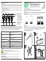
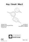
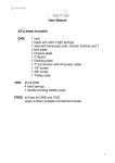
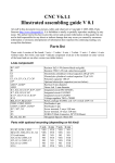
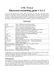
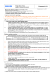
Thermoelectric actuator NC
PUTTING INTO OPERATION
● Before connecting the actuator make sure that the selected model is fully compatible with the available network voltage. All
connections must to be made by qualified personnel and with respect for the overall electrical system - taking care that the
electricity supply is switched off. Incorrect connection may endanger both persons and equipment.
● In order to avoid unnecessary operating time, outside the scheduled heating period switch off the actuator via the main
switch.
● Use of the auxiliary micro-switch in the actuator makes it possible to shut down other equipment, such as circulating pumps,
when valve closes.
● The auxiliary micro-switch is a potential-free contact connected to two black wires. It operates when the actuator opens.
Example of connection to 4 actuators:
BLACK
VA3
TA 1
BLUE
TA 4
TA 3
TA 2
BLACK
TERMINALS
INTO BOILER
VA4
BLUE
BLUE
BLUE
BROWN
VA2
BROWN
NEUTRAL
BLUE
VA1
MC4
MC3
BROWN
MC2
BROWN
MC1
PHASE
BROWN
The thermoelectric actuator
with auxiliary micro-switch is
provided with 4 wires:
● one BLUE wire for connection
to NEUTRAL
● one BROWN wire for connection
to PHASE
● two BLACK wires, connected
to micro-switch, to control
other uses .
TECHNICAL FEATURES
Also shown on the Actuator: Art.1913 - 1914
Art.1923 - 1924
OPENING POWER
Opening power at short time:
Constant power:
Power
CLOSING / OPENING TIME
Art. 1914 - 1924: ca. 180 s
24 V
< 350 mA
125 mA
3W
24 V AC
230 V AC
230 V
< 165 mA
12 mA
3W
ROOM TEMPERATURE LIMITS OF THERMOELECTRIC ACTUATOR
Tmin = -10°C and Tmax = 50°C
SUPPLIED DISCONNECTION
Micro-disconnection type 1B
Comando elettrotermico NC
ISTRUZIONI PER L’USO
ART. 1913-1914-1923-1924
Comando elettrotermico normalmente chiuso
INSTALLAZIONE E FUNZIONAMENTO
Il comando elettrotermico è installabile su valvole termostatizzabili e su collettori termoelettrici.
La sua funzione è quella di regolare automaticamente l’apertura e la chiusura di ogni utenza sulla quale è installato in base al segnale
elettrico ricevuto.
Quando il termostato ambiente o la centralina al quale è collegato il comando invia il segnale, il bulbo interno viene riscaldato
elettricamente e la valvola cambia la sua posizione fino al raggiungimento della completa apertura. La posizione di completa apertura
è riconoscibile dalla sporgenza dall’inserto cilindrico presente sul comando.
Essendo il comando NC - Normalmente Chiuso, in assenza di alimentazione elettrica la valvola è in posizione di chiusura.
49
MC Auxiliary micro-switch
VA Thermoelectric Actuator
winding
TA Thermostat
An example is shown of connection of 4 VA thermoelectric actuators, controlled by 4 TA thermostats. Once the first
thermoelectric actuator is totally open, it closes the circuit of the MC micro-switch, allowing the interconnected equipment e.g.
pump to operate. When the last thermoelectric actuator closes it will switch off the interconnected equipment. The illustration
above shows an example of micro-switch connections to terminals at the boiler for ON/OFF operation of the pump.
WORKING VOLTAGE
FAR Rubinetterie S.p.A. - www.far.eu
44
66
FAR Rubinetterie S.p.A. - www.far.eu
POSIZIONE DI CHIUSURA
POSIZIONE DI APERTURA
MONTAGGIO
- Per effettuare il montaggio del comando sulla valvola, togliere il volantino, il supporto in plastica e avvitare l’adattatore
art.1941. (Fig.1)
- Per effettuare il montaggio sul collettore, togliere il volantino ed avvitare la ghiera direttamente sull’adattatore blu. (Fig. 2)
- Avvitare il comando elettrotermico a mano con leggera pressione e serrare a fondo la ghiera. Non utilizzare chiavi a pappagallo pinze o
altri utensili simili ( Fig.3).
- Il cavo dev’essere installato in modo tale da non venire a contatto diretto con tubi, radiatori etc.
- Effettuare il collegamento elettrico secondo lo schema di Fig.4.
- La testina può essere installata in qualsiasi posizione
1
2
3
4
OVERVOLTAGE CLASS
Art. 1913 - 1923: ca. 90 s
PLASTIC ENVELOPE
CERTIFIED MARK
PROTECTION AS PER EN 60529
Installation in all positions:
The equipment is designed to Class: 2
Nominal impulse voltage: 2500V
Subjected to a ball test, it withstands a temperature of 75°C
IP 54
ACTUATOR
The Actuator is type: 1.AB (voltage variations between 195 V and 250 V)
SPRING TENSION
POLLUTION DEGREE
HUMIDITY
CONNECTION WIRE
130 N
Class II
from 10 up to 90% (not condensated)
MICRO-SWITCH CONTACT
Power intensity permitted:
(Brown + Blue) 2 x 0,35 mm2
1 (0,1)A
AUXILIARY MICRO-SWITCH WIRE
Black 2 x 0,35 mm2
ATTENTION
- The supply wire of this actuator cannot be replaced: if the wire is damaged, the actuator should be rejected
TERMOSTATO AMBIENTE
MARRONE
NERO
- Electric connection and wiring must be carried out in accordance with all national and local regulations
DECLARATION OF CONFORMITY
COMANDO
ELETTROTERMICO
FAR Rubinetterie S.p.A. declares under its responsibility that the thermoelectric actuators are in accordance with community
directives: 2004/108/CE and 2006/95/CE.
TECHNICAL ASSISTANCE
In the event of a problem with the thermoelectric actuator do not tamper with it, contact:
Technical department - FAR Rubinetterie S.p.A.
Via Morena, 20 - 28024 GOZZANO (NO) tel. (0039) 0322.94722/956450 - fax (0039)0322.93952 e-mail: [email protected]
BLU
NERO
Comando elettrotermico NC
BLU
TA 3
MARRONE
BLU
TA 2
MARRONE
BLU
TA 1
MARRONE
BLU
NEUTRO
MARRONE
MESSA IN SERVIZIO
● Prima di collegare elettricamente il comando accertarsi che il modello prescelto sia compatibile con la tensione di rete
disponibile. Tutti i collegamenti devono essere effettuati da personale specializzato rispettando lo schema elettrico ed
accertandosi che la linea elettrica non sia sotto tensione. Allacciamenti errati possono provocare danni sia alle persone sia
al comando.
● Per evitare inutili periodi di funzionamento, in cui l’impianto di riscaldamento non è attivo, mettere i comandi termoelettrici fuori
servizio mediante un interruttore generale.
● Con il microinterruttore ausiliario del comando elettrotermico è possibile interrompere il funzionamento di altre apparecchiature
quali, per esempio, le pompe di circolazione.
● Il microinterruttore ausiliario è un contatto pulito collegato ai due cavi neri. Il microinterruttore si attiva quando la testina arriva
a completa apertura.
Esempio di allacciamento di 4 testine:
Il comando elettrotermico con
NERO
microinterruttore
presenta
MORSETTI
PONTICELLO esteticamente 4 fili:
MC1
MC4
MC2
MC3
NERO IN CALDAIA
● un cavo di colore BLU per la
connessione al NEUTRO.
VA3
VA1
VA4
VA2
● un cavo di colore MARRONE
per la connessione alla FASE.
● due cavi di colore NERO
collegati al microinterruttore
per comandare altre utenze.
BLU
TA 4
FASE
MARRONE
MC Microinterruttore ausiliario
VA Avvolgimento comando
elettrotermico
TA Termostato ambiente
E’ riportato l’esempio di allacciamento di 4 comandi elettrotermici VA comandati da 4 termostati ambiente TA. Il primo
comando elettrotermico che apre, una volta arrivato nella posizione di completa apertura, chiude il circuito di collegamento
dei microinterruttori MC consentendo al componente collegato (ad esempio un circolatore) di attivarsi. L’ultimo comando
elettrotermico che va in chiusura provvederà a disattivare l’apparecchiatura collegata. Nello schema è riportato come esempio
il collegamento dei microinterruttori al ponticello in caldaia per l’accensione e lo spegnimento del circolatore.
DATI TECNICI:
TENSIONE DI ESERCIZIO
Riportata anche sul comando: Art.1913 - 1914
Art.1923 - 1924
CORRENTE DI APERTURA
Corrente di apertura a breve
Corrente permanente
Potenza
TEMPI DI CHIUSURA / APERTURA
Art. 1914 - 1924: circa 180 s
24 V
< 350 mA
125 mA
3W
24 V AC
230 V AC
230 V
< 165 mA
12 mA
3W
FAR Rubinetterie S.p.A. - www.far.eu
Thermoelectric actuator NC
INSTRUCTIONS FOR INSTALLATION
ART. 1913-1914-1923-1924
Normally closed thermoelectric actuator
INSTALLATION AND OPERATION
The thermoelectric actuator can be installed in association with both thermostatic valves and thermoelectric
manifolds. It permits automatic opening and closing of all units to which it is interconnected in response to an
electrical signal.
When the thermostat or control unit – to which the thermoelectric actuator is connected – transmits a signal, the inner element is
electrically heated, thus fully opening the valve. The fully open position can be identified by means of the cilindrical position indicator
on the actuator head.
As the actuator is of the normally closed (NC) type, without an electrical supply the valve will remain shut.
49
44
66
FAR Rubinetterie S.p.A. - www.far.eu
CLOSED POSITION
OPEN POSITION
INSTALLATION
- In order to install the actuator on to the valve, remove the handle, the plastic support and screw on the adapter art. 1941.
(Picture 1)
- In order to carry out installation at the manifold, remove the handle and screw the ring direct on to the blue adapter. (Picture 2)
- Lightly hand-tighten the ring on the thermoelectric actuator. Do NOT use plumbing wrenches or similar tools. (Picture 3)
- Take care to install the wire in such a way that it doesn’t come in direct contact with pipes, radiators, etc…
- Carry out electrical connection as per picture No. 4
- You can install the actuator in any position
LIMITI DI TEMPERATURA AMBIENTE DELLA TESTINA ELETTRICA
Tmin = -10°C e Tmax = 50°C
1
2
3
4
DISCONNESSIONE FORNITA
Microdisconnessione tipo 1B
CATEGORIA DI SOVRATENSIONE
Art. 1913 - 1923: circa 90 s
INVOLUCRO PLASTICO
MARCHIO DI CONTROLLO
TIPO DI PROTEZIONE SECONDO EN 60529
Montaggio in qualsiasi posizione
L’apparecchio rientra nella categoria: 2
Tensione impulsiva nominale: 2500 V
Sottoposto alla prova della biglia, sopporta la temperatura di 75°C
IP 54
ATTUATORE
L’attuatore è di tipo: 1.AB (variazioni di tensione comprese tra 195 V e 250 V)
FORZA DELLA MOLLA
GRADO DI INQUINAMENTO
UMIDITÀ
CAVO DI COLLEGAMENTO
130 N
Classe II
Da 10 fino a 90% non condensata
CONTATTO MICROINTERRUTTORE
Intensità di corrente ammessa:
(marrone + azzurro) 2 x 0,35 mm²
1 (0,1)A
CAVO MICROINTERRUTTORE AUSILIARIO
Nero
2 x 0,35 mm²
AVVERTENZE
- l cavo di alimentazione di questo dispositivo di comando non può essere sostituito: se il cavo viene
THERMOSTAT
BROWN
BLACK
danneggiato, il dispositivo di comando deve essere scartato.
- Il collegamento elettrico ed il cablaggio sono da eseguire esclusivamente secondo le regole locali.
THERMOELECTRIC
ACTUATOR
DICHIARAZIONE DI CONFORMITA’
La FAR Rubinetterie dichiara sotto la propria responsabilità che i servomotori sono conformi alle direttive comunitarie:
2004/108/CE e 2006/95/CE.
ASSISTENZA TECNICA
Per qualunque problema relativo al comando elettrotermico evitare di manomettere il componente e contattare:
Ufficio Tecnico - FAR Rubinetterie S.p.A.
Via Morena, 20 - 28024 GOZZANO (NO) tel. 0322.94722/956450 - fax 0322.93952 e-mail: [email protected]
BLUE
VF144 EDIZIONE N° 2: 15/06/2009
BLACK