1
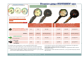
2010 2011 DIVING GAUGES
2010-2011
Iscritta nel registro “15-H4” CODICE DEI COSTRUTTORI NATO al N° A5422
Nato stock number A5422
MEGA SPORT Srl
Via Galileo Galilei, 69/71
10040 - LEINI’ (TO)
ITALY
Tel. 0039 – 011 - 9910239
Fax. 0039 – 011 – 9969724
E-mail: [email protected]
[email protected]
www mega sport com
www.mega-sport.com
[email protected] - [email protected]
1
Terms of sale
¾CUSTOMERS LOGO LINE: the instruments of this catalogue may be supplied whit own logo. You can ask to Mega Sport to make ready the printing loom for
your own brand. The charges for the artwork amounts to € 130,00 for each color, which must be paid only one time. The "STANDARDS" of instruments foresee
the logo printed inside of the handle of the housing or on the back side of the cover.
¾PRICE LIST: All prices are quoted "EX WORKS MEGA SPORT"
¾When you place an order, kindly include full items data, Mega Sport code and description, to avoid errors on the consignment.
¾We will consider approved our order confirmation when upon three days you don’t send us a replay.
¾PAYMENT: IN ADVANCE BY SWIFT TRANSFER AGAINST ORDER CONFIRMATION.
¾WARRANTY CONDITIONS: the instruments have a warranty of one year from user's
user s purchasing date or,
or in lack of this one,
one two years from manufacturing
date. The warranty covers pieces recognized faulty by our technicians for manufacturing or material defect. components exposed to usury, which need usual
maintenance, are not covered by warranty.
The warranty doesn't cover: damage caused by shocks, fallings, or bad use in surface or dive; aspect or functioning defects caused by usual product's
usury or aging. The warranty declines in case of product's manipulation or opening by person lacking of adequate technical training if necessary, or product
tested with not adequate control equipment.
The warranty doesn't include: 1) the periodical maintenance and the replacement of fatigue subject components during the use. 2) the maintenance and
replacement of swivel and respective O-rings. 3) the replacement of flexible tube high pressure "hose".
Repair estimate: not yet under warranty instruments will be subject to repair estimate with payment in advance.
advance The repair will begin only after
customer's confirmation to proceed and respective payment. Delivery costs, for instrument return, is charged to the customer. Not yet under warranty
instrument, not repaired for lack of customer's estimate acceptance, remain at disposal in our warehouse waiting for customer himself‘ s instructions. Six
months passed from not accepted estimate date, in lack of customer's instruction, the forced scrapping will be started.
¾Gli strumenti
t
ti analogici
l i iM
Mega S
Sportt possono essere personalizzati
li ti con il llogo proprio
i d
dell cliente
li t che
h viene
i
realizzato
li t sulla
ll b
base di un di
disegno ffornito
it d
dall cliente
li t
stesso. Il costo delle attrezzature di stampa, da pagare una sola volta, è di 130,00 € per colore presente nel logo.
¾Il generale "STANDARD" degli strumenti prevede l'alloggiamento del logo in base al modello scelto, sul gambo, in posizione frontale o sul retro della
protezione.
¾CONDIZIONI GENERALI DI VENDITA: Tutti i prezzi sono quotati "Franco fabbrica Mega Sport“. Per evitare spiacevoli inconvenienti Vi preghiamo di
inviare i vostri ordini via fax allo 011/9969724 o via E-Mail all’indirizzo [email protected] e di specificare CODICE e descrizioni di ciascun articolo; Vi
preghiamo inoltre di indicare i dati completi per la fatturazione e consegna della merce. La Mega Sport provvederà al più presto ad inoltrare la conferma
d'ordine scritta. Non ricevendo risposta alcuna, trascorsi tre giorni lavorativi, considereremo approvata la conferma d'ordine trasmessa.
¾
¾PAGAMENTI:
ANTICIPATO A MEZZO BONIFICO BANCARIO ALLA CONFERMA D’ORDINE.
’
¾CONDIZIONI DI GARANZIA: Gli strumenti sono garantiti un anno a partire dalla data della prova di acquisto dell'utilizzatore o, in mancanza di quest'ultima,
due anni dalla data di produzione. La garanzia copre i pezzi riconosciuti difettosi dai nostri tecnici per vizio di fabbricazione o del materiale. Non sono coperti
da garanzia tutti quei componenti che, soggetti ad usura, necessitano di ordinaria manutenzione.
La garanzia non copre: i danni causati da colpi, cadute o cattivo utilizzo in superficie od in immersione; i difetti di aspetto o funzionamento causati dalla
normale usura del prodotto o dal suo invecchiamento. La garanzia decade qualora lo strumento risultasse essere stato manipolato o aperto da persona con non
adeguata formazione tecnica all'uopo necessaria o che risultasse essere stato testato con strumentazione di controllo non adeguata.
La g
garanzia non comprende:
p
1)) la manutenzione p
periodica e la sostituzione dei componenti
p
soggetti
gg
ad usura durante l'utilizzo. 2)) la manutenzione e
sostituzione del raccordo girevole "swivel" e delle relative guarnizioni di tenuta. 3) La sostituzione del tubo flessibile alta pressione "frusta".
Preventivo di riparazione: Gli strumenti non più coperti da garanzia saranno assoggettati a preventivo di riparazione con pagamento anticipato. L'inizio
del lavoro di riparazione avverrà solo dopo aver ricevuto la conferma a procedere da parte del cliente ed il relativo pagamento. Le spese di trasporto per il
rientro del materiale reclamato sono a carico del cliente. Gli strumenti non più coperti da garanzia, non ricondizionati per mancata accettazione del preventivo
da parte del cliente, restano a disposizione presso il ns. magazzino in attesa delle disposizioni del cliente stesso. Decorsi 6 mesi dalla data del preventivo non
accettato, in mancanza di definizione da parte del cliente, si procederà alla rottamazione coatta.
[email protected] - [email protected]
2
ACCORDING THE UNI EN 250 NORM
PRESSURE GAUGE BRASS CASE/SYNTHETIC CASE
TECHNICAL DETAILS
Characteristics in common to the two kinds of pressure gauges:
The pressure gauge with H.P. hose satisfies the requisite of the European normative specifications CE EN 250 and is manufactured with nickel-plated brass case or reinforced plastic material at high mechanical performance.
The characteristics of the material in object assure the mechanical resistance and long life on time. The survey of the pressure is submitted to a special bourdon spiral spring in copper-beryllium that it also warranties to the
tool constant precision of reading in the case that this one has suffered bumps or violent shocks.
Pressure gauge in synthetic case’s differences:
The use of special polymers at high resistance and of a simple and ingenious patented system has allowed us to manufacture a small pressure gauge, strong, precise and light which will revolutionize the field of analogical
diving equipment.
equipment The patented system prevents to the case to be in touch with the high pressure of the tank and allows the use of not-metal material keeping a high safety factor
factor. The connection between case and H.P.
H P hose is
simplified (without swivel), and the wet seal is warranted by a single O-ring, reducing the seals respect to standard method. The instrument has not the PVC protection, then the fastidious and repetitive maintenances to
avoid the oxidation are not necessary. The not magnetic synthetic material rends the instrument more adapt to military use.
Instructions for use:
ATTENTION: the pressure gauges working at high pressure risk, in case of failure, the violent ejection of the glass, should an escape of air occurs inside the instrument.
ANTIEXPLOSIVE SYSTEM: the safety device used to protect the diver from this risk is integrated in the PVC casing of the single pressure gauges or of the consoles and/or in the PVC safety ring of the synthetic cases.
THE USE UNDER PRESSION OF THE PRESSURE GAUGE OR OF THE CONSOLE WITHOUT THE ANTIEXPLOSIVE SYSTEM MAY EXPOSE THE DIVER TO A VIOLENT GLASS EJECTION .
- The pressure gauge is made to be used with compressed air only. For the employment with oxygenated mixture (Nitrox) or pure oxygen, see precautions of use notes "PRESSURE GAUGE NITROX/OXYGEN"
- Connect the hose to the high connection of the regulator (H.P. connection 7/16" x 20 - UNF) after preventively having anointed the O-rings with silicon grease. - Use a flat key 14 cm. to close, not forcing the link excessively.
-Don't directly
y look at the tool when you
y
open
p
the tap
p of the tank. - Put the regulator
g
under pressure
p
and verify
y that there are not some losses. - The p
pressure in entrance of the pressure
p
gauge
g g doesn't have to overcome the
value of 300 bar / 3400 psi - Link the hose at the Jacket to avoid pressure gauge traverse.
Maintenance:
- The wear and tear subjects components of the pressure gauge like H.P.hose, pivot pin, O-Rings, must be periodically verified and replaced.
- With the purpose to limit the deterioration of the O-rings we recommend the periodical use of compatible lubricant (ex. silicone grease)
- After the use, rinse the complete pressure gauge with fresh water and dry in the shade and keep the instrument dry.
-Don't use solutions to clean the glass (the raw material could lose his unbreakable characteristic)
PRESSURE GAUGE NITROX/OXYGEN
Characteristics:
The NITROX/OXYGEN PRESSURE GAUGE is 100% oxygen compatible and for mixtures oxygenated type NITROX also. Instructions for the use and maintenance: (look at pressure gauge)
ATTENTION The
ATTENTION:
Th O-rings
O i
off the
th Nitrox/Osxygen
Nit
/O
pressure gauge mustt b
be llubricates
b i t with
ith oxygen-compatible
tibl grease. The
Th use off different
diff
t lubricants,
l b i
t in
i presence off mixtures
i t
enriched
i h d off oxygen, can cause "DANGER Of
Explosion". In the case in wich the instrument has been used with normal compressed air it is necessary, before again using it with enriched air, to proceed to one deep cleaning to eliminate possible signs of contamination
from hydrocarbons or other impurities (elements that could bait a spontaneous combustion). Besides it is necessary to replace the H.P. hose, the O-Rings and the revolving pivot (Swivel) with new one or, however,
accessories that has been used only with mixtures Nitrox/Oxygen only.
ATTENTION: We recommend the substitution of the H.P. hose, the O-Rings and the revolving pivot every two years.
Precisione:
Livello di precisione richiesto dalle normative CE EN 250:
Preciseness:
Standard of precision by CE EN 250 norm
± 5 bar a 40 bar
± 10 bar a 100 bar
± 10 bar a 200 bar
± 10 bar a 300 bar
± 70 psi a 570 psi
± 140 psi a 1.400 psi
± 140 psi a 2.800 psi
± 140 psi a 4.200 psi
MANOMETRO CASSA OTTONE/CASSA SINTETICA
Caratteristiche comuni ai due tipi di manometro:
Il manometro con frusta soddisfa i requisiti delle specifiche normative europee CE EN 250 e può essere del tipo con cassa stampata in corpo unico d'ottone nichelato o materiale termoplastico rinforzato ad alte prestazioni
meccaniche. Le caratteristiche del materiale in oggetto ne assicurano la resistenza meccanica e la durata nel tempo. La rilevazione della pressione è affidata ad uno speciale bourdon a forma di spirale in rame-berillio che
garantisce allo strumento costante precisione di lettura anche nel caso che questo ultimo abbia subito urti o colpi violenti.
Particolarità del manometro con cassa in materiale sintetico:
L’impiego di speciali polimeri ad elevata resistenza e di un semplice ed ingegnoso sistema brevettato ci ha consentito di creare un piccolo manometro, resistente, preciso e leggero che rivoluzionerà il campo della
strumentazione analogica subacquea. Il sistema brevettato impedisce alla cassa di essere a diretto contatto della pressione interna e consente l’utilizzo di materiale non metallico mantenendo un elevato fattore di sicurezza.
La connessione cassa frusta alta pressione è semplificato (assenza di perno girevole) e la tenuta viene garantita da una unica guarnizione riducendo i punti di tenuta rispetto al metodo tradizionale.
tradizionale L’assenza di cuffia di
protezione in PCV non rende necessari i costanti e fastidiosi interventi di manutenzione volti a contenere l’ossidazione della cassa in ottone. Il materiale sintetico “non magnetico” rende lo strumento più adatto all’uso
minitare.
Istruzioni per l'uso:
ATTENZIONE: i manometri subacquei lavorando ad altra pressione sono esposti, in caso di avaria, a rischio di espulsione violenta del vetro in caso di fuga d'aria all'interno dello strumento.
SISTEMA ANTI-SCOPPIO: il sistema di sicurezza adottato per proteggere il subacqueo da questo rischio è integrato nelle cuffie di protezione in PVC dei manometri singoli o delle console e/o nell'anello di sicurezza in PVC
delle versioni con cassa sintetica. L'USO SOTTO PRESSIONE DEL MANOMETRO O DELLA CONSOLE PRIVATI DELL'APPOSITO SISTEMA ANTI-SCOPPIO PUO' ESPORRE AL RISCHIO DI INCIDENTE DA ESPULSIONE
VIOLENTA DEL VETRO DI CHIUSURA.
Per l'impiego con miscela ossigenata (Nitrox) od ossigeno puro, VEDI PRECAUZIONI D'USO SU SCHEDA: MANOMETRO NITROX/OSSIGENO.
- Collegare
g
la frusta all'uscita alta pressione
p
dell'erogatore
g
(H.P.
(
del tipo
p 7/16"
7/
x 20 - UNF)) dopo
p avere preventivamente
p
unto la g
guarnizione con del grasso
g
al silicone.
- Utilizzare una chiave piatta da 14 per la chiusura senza forzare eccessivamente il raccordo. - Non rivolgere il viso direttamente verso lo strumento quando si apre il rubinetto di consenso della bombola.
- Mettere l'erogatore sotto pressione e verificare che non vi siano delle perdite. - La pressione in entrata del manometro non deve per nessun motivo superare il valore di 300 bar / 3400 psi
- Per evitare che il manometro completo di frusta brandeggi, fissarlo al giubbotto idrostatico.
Manutenzione: - I componenti del manometro soggetti ad usura quali, tubo alta pressione, raccordi girevoli "SWIVEL", O-Rings, devono essere periodicamente verificati e sostituiti.
- Al fine di limitare il deterioramento delle guarnizioni di tenuta si consiglia il periodico uso di lubrificante compatibile (es. grasso al silicone)
- Dopo l'uso, risciacquare il manometro completo in acqua dolce, fare asciugare all'ombra e riporre in un luogo asciutto - Non impiegate soluzioni per pulire il vetro (il materiale potrebbe perdere le caratteristiche
d'infrangibilità se aggredito da sostanze non compatibili)
MANOMETRO NITROX/OSSIGENO
Caratteristiche: - Il manometro NITROX/OSSIGENO è compatibile al 100% ossigeno ed è preparato anche per miscele ossigenate tipo NITROX.“Istruzioni per l'uso” & “Precisione” : (vedi manometro)
guarnizioni di tenuta del manometro Nitrox/Ossigeno
/
g
devono essere lubrificate con grasso
g
ossigeno-compatibile.
g
p
L'utilizzo di lubrificanti diversi,, in presenza
p
di miscele arricchite d'ossigeno,
g
, può
p
causare
ATTENZIONE: Le g
"RISCHIO DI ESPLOSIONE". Nel caso in coi il manometro è stato utilizzato con normale aria compressa è necessario, prima di usarlo nuovamente con aria arricchita, procedere ad una approfondita pulitura per eliminare
eventuali segni di contaminazione da idrocarburi od altre impurità (elementi che potrebbero innescare una combustione spontanea). E' inoltre necessario sostituire il tubo alta pressione, le guarnizioni di tenuta ed il perno
girevole (Swivel) con altri nuovi o comunque che siano stati usati solo con miscele Nitrox/Ossigeno. ATTENZIONE: Si consiglia la sostituzione del tubo alta pressione, delle guarnizioni di tenuta e perni girevoli ogni due anni.
[email protected] - [email protected]
3
ACCORDING TO EN 250 & EN 13949
PRESSURE GAUGE BRASS CASE/SYNTHETIC CASE
QUALITY CONTROL PROCEDURES
All analogic pressure gauges are tested and are in compliance with current European regulations CE UNI EN 250 and EN 13949. The results of the tests carried out during all phases of production
and testing both intermediate and final prove the compliance of the pressure gauges with the European regulations stated above.
DESCRIPTION OF PRODUCTION AND TESTING CYCLE OF ALL ANALOGICAL PRESSURE GAUGES:
g of the central p
pin to the CU BE tube.
1.
- Silver-soldering
2. - Hairspring: flattening of the tube, creation of the CU BE hairspring and temper.
3. - Soft-soldering of the CU BE hairspring to the brass case (for the synthetic case mounting of the sealing O-rings).
4. - Sealing test of the solderings and/or O-rings by hydraulic equipment with 5 cycles from 0 to 420 bar lasting 30 seconds each
5. - Calibration of the pressure gauge by a control pressure gauge (precision ± 0,6%) and checking of the same every 2 months by digital pressure gauge (± 0,05% of the value of the end scale).
6. - Precision check of the pressure gauge and assessment of compliance with tolerance limits as required in the European regulations CE UNI EN 250.
Precision standards required by the regulations CE UNI EN 250 in bar/psi:
± 5 bar at 40 bar
± 70 psi at 570 psi
± 10 bar at 100 bar
± 140 psi at 1.400 psi
± 10 bar at 200 bar
± 140 psi at 2.800 psi
± 10 bar at 300 bar
± 140 psi at 4.200 psi
7.
8.
9.
10.
11.
Mounting of the glass with appropriate sealing O-ring.
Air testing
g of each p
pressure g
gauge
g for 12 hours at 200 bar air p
pressure for 2nd check of the soldering
g and strength
g of the CU BE hairspring
p g
Water-tightness check of each pressure gauge by 10 immersion cycles in water from 0 to 60 metres lasting around 2 hours.
Micro seepage check of each pressure gauge consisting in placing inside an oven at 50°C for 30 minutes and, once the pressure gauge is restored to ambient temperature, verification of the
potential presence of condensate under the glass.
Mounting of the hose and immersion of the complete pressure gauge in water for 10 minutes at 200 bar air pressure for checking potential air leaks of the swivel and/or hose and regular
operation of the needle.
MANOMETRO CASSA OTTONE/CASSA SINTETICA
I manometri analogici subacquei vengono testati in base alle disposizioni delle normative CE UNI EN 250 e EN 13949. I risultati delle prove eseguite durante le varie fasi della lavorazione ed il
collaudo finale soddisfano i requisiti previsti dalle norme stesse.
DESCRIZIONE DEL CICLO DI LAVORAZIONE E COLLAUDO DI TUTTI I MANOMETRI ANALOGICI SUBACQUEI:
1.
Saldatura in lega d’argento del perno centrale al tubo manometrico in rame berillio.
2. Spirale in rame berillio: schiacciamento del tubo, costruzione della spirale e trattamento termico (tempra).
3. Saldatura in lega di stagno della spirale alla cassa in ottone (per la versione cassa sintetica montaggio guarnizioni OR).
4. Collaudo tenuta delle saldature e guarnizioni mediante macchina idraulica con 5 cicli da 0 a 420 bar della durata di 30 secondi ciascuno.
5. Taratura del manometro subacqueo mediante manometro di controllo (precisione ± 0,6%) e verifica del medesimo ogni 2 mesi tramite manometro digitale (± 0,05% del valore di fondo scala).
6. Controllo della precisione del manometro e verifica della sua conformità alle tolleranze previste dalle norme CE UNI EN 250.
Livelli di precisione richiesti dalle normative CE UNI EN 250 in bar/psi:
± 5 bar a 40 bar
± 70 psi a 570 psi
± 10 bar a 100 bar
± 140 psi a 1.400 psi
± 10 bar a 200 bar
± 140 psi a 2.800 psi
± 10 bar a 300 bar
± 140 psi a 4.200 psi
7.
8.
9.
10.
11.
Applicazione del vetro con relativo OR di tenuta.
Collaudo di tutti i manometri per 12 ore a 220 bar di pressione con aria per una 2° verifica delle saldature e resistenza della spirale in rame berillio.
Collaudo tenuta stagna di ciascun manometro mediante 10 cicli di immersione in acqua da 0 a 60 metri per una durata complessiva di circa 2 ore.
Collaudo micro infiltrazioni di ciascun manometro consistente nella messa in forno a 50°C per 30 minuti e, una volta lo strumento ritornato a temperatura ambiente, successivo controllo
dell’eventuale presenza di condensa sotto il vetro.
Montaggio della frusta ed immersione del manometro completo in acqua per 10 minuti a 200 bar di pressione di aria per il controllo di eventuali perdite dello swivel e/o frusta e regolare
funzionamento della lancetta manometro.
[email protected] - [email protected]
4
DEPTH GAUGE
ACCORDING TO UNI EN 13319 NORM
TECHNICAL DETAILS
Characteristics:
The DEPTH GAUGE satisfied the requisite of the CE EN 13319 NORM.
-copper-berylium membrane system of reading that elevated sensibility and precision.
-dial with parabolic scale to improve the precision of reading on the various reached depths and on the deco stages.
Instructions for the use:
- before the dive reset the red pointer of maximum depth. Complete the zero reset rotating the screw anticlockwise you find in the center glass.
- never overcome the maximum attainable depth from the tool (equivalent to the end scale printed on the dial of the tool)
Precision:
Our depth gauge is set for dive in sea water. The reading achieved by the tool employed in fresh water (or checked with tools calibrated not for sea water) it results therefore lower of around 2,4 cms. for meter (0,29 Inch
for Foot) because of the different density of the water.
Maintenance:
- treat the depth gauge as a tool of precision. Avoid therefore violent bumps that could influence on the precision of reading, and therefore on the reliability of the tool.
- The depth gauge set in console together with the pressure gauge, have to be protected from bumps or rub on the ground during the transport anchoring the console to the cylinder or to the Jacket to avoid problem.
-Don't expose the tool to sources of heat.
- The employment over the maximum value of suitable scale on the dial can damages the tool in irremediable way.
-Rinse the depth gauge with fresh water after every dive and not employ solutions to clean the glass (the material could lose the characteristics of impermeability or transparency if put in contact with not compatible
substances).
ZERO ADJUSTMENT DEPTH GAUGE
Professional Depth Gauge (manufactured in simple or double scale) projected to get an elevated sensibility and precision for professional employment of the tool. Realized in conformity to the CE EN 13319 norm.
Characteristics:
- special beryl membrane device with cogwheels of a clock to allow better reading during dive or decompression .
- dial with parabolic luminescent scale, accuracy ± 1,5% maximum depth indicator.
-zero adjustment system to compensate temperature and ambient pressure.
Indication before dive:
- dive for a few minutes the tool in the water where you will perform the immersion to condition it to the temperature of exercise.
exercise Make sure to check the depth gauge calibration when the tool is still cold
cold, at the end of
each dive.
- before the immersion to reset the red pointer of maximum depth.
- don't overcome the maximum attainable depth from the tool (equivalent to the end of scale of the tool)
Precision and Maintenance: (read DEPTH GAUGE)
Livello di precisione richiesto dalle normative CE UNI EN 13319 (temp. acqua/ambiente da +10 C a +15 C):
[+ 0,8 m. - 0,4 m.] a 3 metri di profondità
[+ 1,0 m. - 1,2 m.] a 30 m. di profondità
[[+ 0,8
, m. - 0,4
,4 m.]] a 6 "
“
[[+ 1,0
, m. - 1,5
,5 m.]] a 45 "
"
[+ 0,8 m. - 0,8 m.] a 9 "
"
[+ 1,0 m. - 1,5 m.] a 60 "
“
[+ 1,0 m. - 1,2 m.] a 15 "
"
Standard of precision by CE EN 13319 norm (at a water/ambient temperature in a range of +50 F - +59 F:
[+ 2,62 Ft - 1,31 Ft ] a 10 depth Feet
[+ 3,28 Ft - 3,93 Ft ] a 100 depth Feet
[[+ 2,62
, Ft - 1,31
,3 Ft ] a 20 "
“
[[+ 3,
3,28 Ft - 4,9
4,92 Ft ] a 150
5
"
"
[+ 2,62 Ft - 2,62 Ft ] a 30 "
“
[+ 3,28 Ft - 4,92 Ft ] a 200 "
"
[+ 3,28 Ft - 3,93 Ft ] a 50 "
"
PROFONDIMETRO
Caratteristiche:Il profondimetro soddisfa i requisiti delle specifiche normative CE EN 13319.
- sistema di lettura mediante membrana al rame berillio e/o bronzo fosforoso che conferisce, al sistema degli ingranaggi del tipo ad orologeria, un'elevata sensibilità e precisione di lettura.
- quadrante con scala parabolica adatta a migliorare la precisione di lettura alle profondità legate alle eventuali tappe di decompressione.
Istruzioni per l'uso:
- prima dell'immersione azzerare la lancetta rossa di massima profondità, portando la stessa sopra la lancetta nera di esercizio. Compiere l'azzeramento ruotando in senso anti-orario la vite che trovate nel centro vetro.
- non superare mai la massima profondità raggiungibile dallo strumento (equivalente al fondo scala strumento)
Precisione:Il nostro profondimetro è tarato per immersioni in acqua marina. La lettura conseguita dallo strumento impiegato in acqua dolce (ovvero controllati con strumenti calibrati per acqua non di mare) risulta
quindi inferiore di circa 2,4 cm. per metro (0,29 Inch per Foot) a causa della diversa densità dell'acqua.
Manutenzione: - Trattate il profondimetro come uno strumento di precisione. Evitate quindi di assoggettare lo strumento a colpi o urti violenti che potrebbero influire sulla precisione di lettura, e quindi sull'affidabilità
dello strumento.
- Montato in consolle insieme al manometro, il profondimetro deve essere protetto da urti o strusciamenti sul terreno durante il trasporto eventualmente ancorando la consolle alla bombola o al Jacket per evitarne il
brandeggio.
- Evitate di esporre lo strumento a fonti di calore.
- L'impiego oltre il valore massimo di scala indicata sul quadrante danneggia lo strumento in modo irrimediabile.
Lavate il profondimetro con acqua dolce dopo ogni immersione e non impiegate soluzioni per pulire il vetro (il materiale potrebbe perdere le caratteristiche d'impermeabilità
d impermeabilità e/o trasparenza qualora aggredito da
sostanze non compatibili).
PROFONDIMETRO AZZERABILE
Il profondimetro azzerabile è stato progettato per ottenere un'elevata sensibilità e precisione per impiego professionale dello strumento. Realizzato in conformità alle specifiche normative CE EN 13319.
Caratteristiche:- sistema di lettura mediante membrana al rame berillio che conferisce, al sistema degli ingranaggi del tipo ad orologeria, un'elevata sensibilità e precisione di lettura.
- quadrante con scala parabolica adatta ad una migliore lettura in fase di immersione e di decompressione.
- sistema di azzeramento studiato per compensare gli sbalzi di temperatura e/o di pressione atmosferica.
- tenere immerso per qualche minuto lo strumento nell'acqua dove eseguirete l'immersione per condizionarlo il più possibile alla temperatura d'esercizio.
Istruzioni per l'uso: - a condizionamento avvenuto, portare a zero la lancetta nera ruotando il vetro zigrinato del profondimetro (impugnare il vetro sulla zigrinatura laterale appositamente studiata per agevolare questa
p
)
operazione).
- prima dell'immersione azzerare la lancetta rossa di massima profondità, portando la stessa sopra la lancetta nera di esercizio. Compiere l'azzeramento ruotando in senso antiorario la vite che trovate nel centro vetro.
- non superare mai la massima profondità raggiungibile dallo strumento (equivalente al fondo scala strumento)
Precisione e Manutenzione: vedi PROFONDIMETRO
[email protected] - [email protected]
5
ACCORDING TO UNI EN 13319
DEPTH GAUGE
QUALITY CONTROL PROCEDURES
All analogic depth gauges are tested and are in compliance with current European regulations CE UNI EN 13319. The results of the tests carried out during all phases of production and testing
both intermediate and final prove the compliance of the depth gauges with the European regulations stated above.
DESCRIPTION OF PRODUCTION AND TESTING CYCLE OF ALL ANALOGICAL DEPTH GAUGES:
1
1.
Thermal cycle (ageing and dimensional/thermal stability of the raw materials) of the components of mechanism and bearing: for their dimensional stability they are tested from -20°C
20 C to
+80°C for 24h (it must be pointed out that current European regulations require a test at temperatures from -20°C to +60°C for 20 minutes only).
2. Assembly of the mechanism on the casing of the depth gauge.
3. Calibration of the depth gauge by a control pressure gauge (precision ± 0,6%) and checking of the same every 2 months by digital pressure gauge (± 0,05% of the value of the end scale).
4. Mounting of the glass in polycarbonate with appropriate sealing O-ring.
5. Air testing of each depth gauge for 30 minutes at -50 metres to check the possible presence of small air infiltrations inside the gauge itself.
6. Precision check of the gauge and assessment of compliance with tolerance limits as required in the European regulations CE UNI EN 13319.
7
7.
Water-tightness
Water
tightness check of each depth gauge by 10 immersion cycles in water from 0 to 60 metres lasting around 2 hours.
hours
8. Micro seepage check of each depth gauge consisting in placing inside an oven at 50°C for 30 minutes and, once the depth gauge is restored to ambient temperature, verification of the
potential presence of condensate under the glass.
9. Final test of the depth gauge by precision test and assessment of compliance with the European regulations CE UNI EN 13319.
Precision standards required by the regulations CE UNI EN 13319 in metres (at a water/ambient temperature in a range of +10 C - +15 C):
[+ 0,8 m. - 0,4 m.] to a depth of 3 metres
[+ 1,0 m. - 1,2 m.] to a depth of 30 metres
[+ 0,8 m. - 0,4 m.] to a depth of 6 metres
[+ 1,0 m. - 1,5 m.] to a depth of 45 metres
[+ 0,8 m. - 0,8 m.] to a depth of 9 metres
[+ 1,0 m. - 1,5 m.] to a depth of 60 metres
[+ 1,0 m. - 1,2 m.] to a depth of 15 metres
Precision standards required by the regulations CE UNI EN 13319 in feet (at a water/ambient temperature in a range of +50 F - +59 F):
[+ 2,62 Ft - 1,31 Ft] to a depth of 10 feet
[+ 3,28 Ft - 3,93 Ft] to a depth of 100 feet
[+ 2,62 Ft - 1,31 Ft] to a depth of 20 feet
[+ 3,28 Ft - 4,92 Ft] to a depth of 150 feet
[+ 2,62 Ft - 2,62 Ft] to a depth of 30 feet
[+ 3,28 Ft - 4,92 Ft] to a depth of 200 feet
[ 3,28
[+
8 Ft - 3,93 Ft] to
t ad
depth
th off 50 ffeett
PROFONDIMETRO
I profondimetri analogici vengono testati in base alle disposizioni delle normative CE UNI EN 13319. I risultati delle prove eseguite durante le varie fasi della lavorazione ed il collaudo finale
soddisfano i requisiti previsti dalle norme stesse.
DESCRIZIONE DEL CICLO DI LAVORAZIONE E COLLAUDO DI TUTTI I PROFONDIMETRI ANALOGICI:
1.
Ciclo termico (invecchiamento e stabilizzazione dimensionale e termica delle materie prime) dei componenti il movimento ad orologeria e suo supporto: per la stabilizzazione dei medesimi
alle variazioni dimensionali vengono sottoposti a test da -20°C a +80°C per 24h (va precisato che le normative vigenti prevedono un test con temperature da -20°C a +60°C x soli 20 minuti).
2. Assemblaggio degli ingranaggi ad orologeria (movimento) sul corpo profondimetro.
3. Taratura del profondimetro mediante manometro di controllo (precisione ± 0,6%) e verifica del medesimo ogni 2 mesi tramite manometro digitale (± 0,05% del valore di fondo scala).
4. Applicazione del vetro in policarbonato con relativo OR di tenuta.
5. Collaudo in aria di ciascun profondimetro per 30 minuti a -50 metri per verificare l’eventuale esistenza di minuscole infiltrazioni d’aria all’interno dello strumento stesso.
6. Controllo della p
precisione del p
profondimetro e verifica della sua conformità alle tolleranze p
previste dalle norme CE UNI EN 13319.
33 9
7. Collaudo tenuta stagna di ciascun profondimetro mediante 10 cicli di immersione in acqua da 0 a 60 metri per una durata complessiva di circa 2 ore.
8. Collaudo micro infiltrazioni di ciascun profondimetro consistente nella messa in forno a 50°C per 30 minuti e, una volta lo strumento ritornato a temperatura ambiente, successivo controllo
dell’eventuale presenza di condensa sotto il vetro.
9. Collaudo finale del profondimetro consistente nel controllo della precisione e verifica della sua conformità alle tolleranze previste dalle norme CE UNI EN 13319.
Livello di precisione richiesto dalle normative CE UNI EN 13319:
[+ 0,8 m. - 0,4 m.] a 3 metri di profondità
[+ 1,0 m. - 1,2 m.] a 30 metri di profondità
[ 0,8
[+
8 m. - 0,4 m.]] a 6 metrii di profondità
f di à
[ 1,0 m. - 1,5 m.]] a 45 metrii di profondità
[+
f di à
[+ 0,8 m. - 0,8 m.] a 9 metri di profondità
[+ 1,0 m. - 1,5 m.] a 60 metri di profondità
[+ 1,0 m. - 1,2 m.] a 15 metri di profondità
[email protected] - [email protected]
6
TECHNICAL DETAILS
UNDERWATER COMPASS
•USER GUIDE
The compass is mainly used to follow a predetermined direction. The red line on the cover glass, points out the direction that you need to take.
•EXAMPLE: If you want to take a direction with orientation 120°;
rotate the external ring in manner to have the number 12 (120°) lined- up to the red line of the glass.
•JOURNEY THERE: (orientation to 120°): check to have correctly lined up the point 12 with the red line on the side window. You can note that the pointer is positioned on the 0 of the
revolving ring(1). Every deviation of the diver from the original direction results evident because the index of the North and the numbers of reference lined up with the red line, have
leaved the original alignment.
•JOURNEY BACK: The run back is exactly 180° respect the direction of going (120° + 180° = 300°). The number 30 (300°) has to be on the red line of the side window and accordingly the
needle of the compass is on the North at the reference 18 (180°) of the revolving ring.
•MAINTENANCE:
Always avoid the direct exposition of the tool to the sun or to sources of heat and rinse after every dive with fresh water.
Direzione di ritorno a
30 (300°)
Direzione di andata a 12
(120°)
Back heading to 30 (300°)
there heading to 12 (120°)
y
y
y
y
y
ISTRUZIONI PER L’USO
La bussola si utilizza in immersione principalmente per orientarsi verso una direzione predeterminata. La linea rossa di fede sul vetro trasparente, indica la direzione che
desiderate prendere.
ESEMPIO V
ESEMPIO:
Volete
l t prendere
d
una direzione
di
i
con orientamento
i t
t 120°;
°
Ruotare la ghiera esterna e posizionare il numero 12 (120°) allineato alla linea rossa di fede tracciata sul vetro.
PERCORSO DI ANDATA (orientamento a 120°): Verificare di aver correttamente allineato il punto 12 della ghiera esterna con la linea rossa di fede stampata sulla finestra laterale.
Di conseguenza l’ago della bussola si posizionerà con riferimento NORD allineato sullo 0 della ghiera girevole (1). Ogni deviazione del sub da tale direzione risulta evidente perché
l’indice del NORD ed i numeri di riferimento allineati con la riga rossa di fede, si sono mossi dall’allineamento originale.
PERCORSO INVERSO: Nel percorso di ritorno, la direzione è esattamente contraria [180° rispetto la direzione di andata (120° + 180° = 300°)]. Il numero 30 (300°) deve essere
sulla linea rossa della finestra laterale e di conseguenza l’ago della bussola punterà il NORD sul riferimento 18 (180°) della ghiera girevole.
MANUTENZIONE:
Evitare di esporre
p
lo strumento al sole o a fonti
f
di calore e lavatelo in acqua
q
dolce dopo
p ogni
g immersione.
[email protected] - [email protected]
7
Dial scales availability/
/possibilità di scale quadrante
psi
bar
Pressure gauge Ø 60 mm. Manometro Ø 60 mm.
According to CE UNI EN 250
bar/psi
Pressure gauge brass case 60 mm.
diameter.
With tempered antiscratch mineral glass
MINERAL
MINERAL
c/ Frusta HP 12 cm. w/TECHNO
HP hose 12 cm.
BRASS CASE - (1) (25)
BRASS CASE - (1) (8) (25)
Con Frusta HP 80 cm – With HP hose 80 cm
Con Frusta HP 12 cm – With HP hose 12 cm
Manometro con cassa ottone Ø 60 mm.
e vetro minerale temprato anti-graffio
Brass case - basic model
Cassa ottone - modello
C
d ll b
base
(0)
SCALE
NITROX/OXYGEN
714
763
714/763
714 TH
763 TH
714/763 TH
400 bar
5000 psi
400 bar/5000 psi
400 bar
5000 psi
400 bar/5000 psi
764
765
764/765
764 TH
765 TH
764/765 TH
730
736
730/736
730 TH
736 TH
730/736 TH
(0) (7) UNI EN 13949
(5)
MILITARY
TRITEC
(0) standard colour of the dial: Yellow //colore standard del quadrante: giallo
(1) 200 m. (660 Ft) depth-resisting mineral glass //Vetro minerale resistente fino a 200 metri
di profondità
(5) Militaryy ((Nato stock number A5422)
54 ) black dial with special
p
luminescent scale in Tritec
pigment (stronger light intensity)/ / Military (codice Costruttore Nato A5422) quadrante
nero con scala a speciale luminescenza di lunga durata al tritec.
[email protected] - [email protected]
(7) for special use (oxygen or nitrox) with hose protectors in green PVC//Per applicazioni
speciali ossigeno e/o nitrox (salva-frusta di colore verde)
(8) for technical use inclusive H.P. hose 12 cm. lengh. //Per applicazioni tecniche con frusta
alta pressione da 12 cm.
(25) with own logo inside of the back face of the item. //con logo inserito nella parte posteriore
dello strumento.
strumento
8
Dial scales availability/
/possibilità di scale quadrante
psi
bar
Pressure gauge 55 mm. diameter
Manometro diametro 55 mm.
According to C E UNI EN 250 < > International patent pending
bar/psi
Pressure gauge synthetic case 55 mm.
diameter.
Manometro con cassa sintetica Ø 55 mm.
Plastic case basic model
(0)
Cassa plastica modello base
SCALE
SYNTEK
SYNTEK TECHNO
SYNTHETIC CASE - (1) (25)
SYNTHETIC CASE - (1) (8) (25)
Con Frusta HP 80 cm – With HP hose 80 cm
Con Frusta HP 12 cm – With HP hose 12 cm
414
463
414/463
414 TH
463 TH
414/463 TH
400 bar
5000 psi
400 bar/5000 psi
400 bar
5000 psi
400 bar/5000 psi
464
465
464/465
464 TH
465 TH
464/465 TH
430
436
430/436
430 TH
436 TH
430/436 TH
NITROX/OXYGEN
(0) (7) UNI EN 13949
(5)
MILITARY
TRITEC
NO MAGNETIC
(0) standard colour of the dial: Yellow //colore standard del quadrante: giallo
(1) 200 m. (660 Ft) depth-resisting glass //Vetro resistente fino a 200 metri di profondità
(5) Military (Nato stock number A5422) black dial with special luminescent scale in Tritec
pigment
p
g
((stronger
g light
g intensity)/
y)/ / Militaryy ((codice Costruttore Nato A5422)
54 ) q
quadrante
nero con scala a speciale luminescenza di lunga durata al tritec.
[email protected] - [email protected]
(7) for special use (oxygen or nitrox) with hose protectors in green PVC//Per applicazioni
speciali ossigeno e/o nitrox (salva-frusta di color verde)
(8) for technical use inclusive H.P. hose 12 cm. lengh. //Per applicazioni tecniche con frusta
alta pressione da 12 cm.
((25)
5) with own logo
g inside of the back face of the item. //
//con logo
g inserito nella p
parte p
posteriore
dello strumento.
9
According to CE UNI EN 250
Dial scales availability/
/possibilità di scale quadrante
According to CE UNI EN 250 < > International patent pending
Depth
h gauge SIGMA Ø 55 mm.
bar
metri
bari/psi
metri/feet
psi
feet
SYNTEK 2
Pressure gauge synthetic case - complete of H.P. hose 80 cm. Length
SYNTHETIC CASE - (1) (25)
Manometro con cassa sintetica completo di frusta H.P. 80 cm.
Con Frusta HP 80 cm – With HP hose 80 cm
pressure gauge synthetic case console basic model
Consolle con manometro cassa sintetica modello base
(0)
SCALE
K 414
K 463
K 414/K463
400 bar
70 meters
5000 psi
220 feet
400 bar/5000 psi
70 meters/220 feet
K 464
K 465
K 464/K465
K 430
K 436
K 430/K436
Pressure gauge 55 mm.
diameter
NITROX/OXYGEN
(0)(7) UNI EN 13949
(5)
MILITARY
TRITEC
(0) standard colour of the dial: Yellow //colore standard del quadrante: giallo
(1) 200 m. (660 Ft) depth-resisting glass //Vetro resistente fino a 200 metri di profondità
(5) Military (Nato stock number A5422) black dial with special luminescent scale in Tritec
pigment (stronger light intensity)/ / Military (codice Costruttore Nato A5422)
quadrante nero con scala a speciale luminescenza di lunga durata al tritec.
tritec
[email protected] - [email protected]
(7) for special use (oxygen or nitrox) with hose protectors in green PVC//Per applicazioni
speciali ossigeno e/o nitrox (salva-frusta di color verde)
(25) with own logo inside of the back face of the item. //con logo inserito nella parte
posteriore dello strumento.
10
According to CE UNI EN 250
According to CE UNI EN 250 < > International patent pending
Dial scales availability/
y/
/possibilità di scale quadrante
bar
psi
Compass ORION Ø 55 mm.
bar/psi
Pressure gauge synthetic material case - complete of H.P. hose 80 cm.
Length
SYNTEK 2 C
SYNTHETIC CASE - (1) (25)
Manometro con cassa sintetica completo di frusta H.P. 80 cm.
Con Frusta HP 80 cm – With HP hose 80 cm
pressure gauge synthetic case console basic model
Consolle con manometro cassa sintetica modello base
(O)
KC 414
KC 463
KC 414/KC 463
SCALE
400 bar
5000 psi
400 bar/
5000 psi
KC 464
KC 465
KC 464/KC 465
NITROX/OXYGEN
(0)(7) UNI EN 13949
(5)
MILITARY
TRITEC
Pressure gauge 55 mm. diameter
KC 430
(0) standard colour of the dial: Yellow //colore standard del quadrante: giallo
KC 430/KC 436
(7) for special use (oxygen or nitrox) with hose protectors in green PVC//Per applicazioni
speciali ossigeno e/o nitrox (salva-frusta di color verde)
(25) with own logo inside of the back face of the item. //con logo inserito nella parte
posteriore dello strumento.
(1) 200 m. (660 Ft) depth-resisting glass //Vetro resistente fino a 200 metri di profondità
(5) Military (Nato stock number A5422) black dial with special luminescent scale in Tritec
pigment
p
g
((stronger
g light
g intensity)/
y)/ / Militaryy ((codice Costruttore Nato A5422)
54 )
quadrante nero con scala a speciale luminescenza di lunga durata al tritec.
[email protected] - [email protected]
KC 436
11
According to CE UNI EN 250
Dial scales availability/
/possibilità di scale quadrante
According to CE UNI EN 250 < > International patent pending
Compass ORION Ø 55 mm.
Depth gauge SIGMA Ø 55 mm.
bar
metri
Pressure gauge 55 mm.
diameter
bari/psi
metri/feet
psi
feet
Pressure gauge synthetic material case - complete of H.P. hose
80 cm. Length
SYNTEK 3
SYNTHETIC CASE - (1) (25)
Con Frusta HP 80 cm – With HP hose 80 cm
Manometro con cassa sintetica completo di frusta H.P. 80 cm.
pressure gauge synthetic case console basic model
Consolle con manometro cassa sintetica modello base
(O)
SCALE
NITROX/OXYGEN
X 414
X 463
X 414/X 463
400 bar
70 meters
5000 psi
220 feet
400 bar/5000 psi
70 meters/220 feet
X 464
X 465
X 464/X 465
X 430
X 436
X 430/X 436
(0)(7) UNI EN 13949
(5)
MILITARY
TRITEC
(0) standard colour of the dial: Yellow //colore standard del quadrante: giallo
(1) 200 m. (660 Ft) depth-resisting glass //Vetro resistente fino a 200 metri di profondità
(5) Military (Nato stock number A5422) black dial with special luminescent scale in Tritec
pigment (stronger light intensity)/ / Military (codice Costruttore Nato A5422) quadrante
nero con scala a speciale luminescenza di lunga durata al tritec.
[email protected] - [email protected]
(7) for special use (oxygen or nitrox) with hose protectors in green PVC//Per applicazioni
speciali ossigeno e/o nitrox (salva-frusta di color verde)
(25) with own logo inside of the back face of the item. //con logo inserito nella parte
posteriore dello strumento.
12
PRESSURE GAUGES/manometri
According to CE UNI EN 250
Pressure gauge 55 mm. diameter
Dial scales availability/
/possibilità di scale quadrante
bar
psi
Mini Index
TECHNO
BRASS CASE - (1) (22)
BRASS CASE - (1) (8) (25)
Frusta HP 80 cm - HP hose 80 cm
Con Frusta HP 12 cm - With HP hose 12 cm
bar/psi
Mini Light
SYNTHETIC CASE - (1) (22)
MINI INDEX
(0)
BRASS case pressure gauge STANDARD MODEL
MANOMETRO cassa in OTTONE nichelato, modello base
MINI LIGHT
SYNTHETIC case pressure gauge STANDARD MODEL
MANOMETRO cassa SINTETICA nichelato, modello base
( )
(0)
SCALE
TECHNO Light
SYNTHETIC CASE - (1) (8) (25)
214
663
214/663
209 TH
219 TH
209/219 TH
214 /E
663 /E
214-663/E
209 TH/E
219 TH/E
209/219 TH/E
400 bar
5000 psi
400bar/
5000psi
400 bar
5000 psi
400bar/
5000psi
MINI INDEX
(0)(7)
NITROX/OXYGEN
664
665
664/665
232 TH
234 TH
232/234 TH
(0)(7)
NITROX/OXYGEN
664/E
665/E
664-665/E
232 TH/E
234 TH/E
232/234 TH/E
(5)
MILITARY TRITEC
630
636
630/636
259 TH
261 TH
259/261 TH
(5)
MILITARY TRITEC
630/E
636/E
630636/E
259 TH/E
261 TH/E
259/261 TH/E
UNI EN 13949
MINI LIGHT
UNI EN 13949
MINI INDEX
MINI LIGHT
(0) standard colour of the dial Yellow //colore standard del quadrante giallo
(1 200 m. (660 Ft) depth-resisting glass / Vetro resistente fino a 200 metri di profondità
(5) Military (Nato stock number A5422) black dial with special luminescent scale in Tritec
pigment (stronger light intensity)// Military (codice Costruttore Nato A5422) quadrante
nero con scala a speciale luminescenza di lunga durata al tritec.
(7) or special use (oxygen or nitrox) with housing in green PVC//Per applicazioni speciali
[email protected] - [email protected]
ossigeno e/o nitrox cuffia di protezione color verde
(8) for technical use inclusive H.P. hose 12 cm. Lengh // Per applicazioni tecniche con frusta alta
pressione da 12 cm. protezione corta
(22) with own logo inside of the handle of the instrument //con logo inserito sul gambo dello
strumento
(25) with own logo inside of the back face of the item.// con logo inserito nella parte posteriore
dello strumento.
13
ccc
CONSOLES
2
Dial scales availability/ /possibilità
di scale quadrante
According to CE UNI EN 250/In conformità con le normative CE UNI EN 250
psi
feet
bar
metri
bari/psi
metri/feet
Mini Index 2
Depth gauge SIGMA Ø 55 mm.
BRASS CASE - (1) (22)
Con Frusta HP 80 cm – With HP hose 80 cm
Mini Light 2
SYNTHETIC CASE - (1) (22)
Con Frusta HP 80 cm – With HP hose 80 cm
Mini INDEX 2
L 214
L 663
L 214/663
(0)
L 214 /E
L 663 /E
L 214-663/E
SCALE
400 bar
70 m
5000 psi
220 feet
400bar-70m/
5000psi-220Ft
L 664
L 665
L 664/665
L 664/E
L 665/E
L 664-665/E
L 630
L 636
L 630/636
L 630/E
L 636/E
L 630-636/E
BRASS case pressure gauge STANDARD MODEL
(0)
MANOMETRO cassa in OTTONE nichelato, modello base
Mini LIGHT 2
SYNTHETIC case pressure gauge STANDARD MODEL
MANOMETRO cassa SINTETICA, modello base
Mini INDEX 2
UNI EN 13949
(0)(7)
Mini LIGHT 2
(0)(7)
UNI EN 13949
NITROX/OXYGEN
NITROX/OXYGEN
Pressure gauge 55 mm. diameter
Mini INDEX 2
(5)
MILITARY
TRITEC
Mini LIGHT 2
(5)
MILITARY
TRITEC
(0) standard colour of the dial Yellow //colore standard del quadrante giallo
(1) 200 m. (660 Ft) depth-resisting glass //Vetro resistente fino a 200 metri di profondità
(5) Military (Nato stock number A5422) black dial with special luminescent scale in Tritec
pigment (stronger light intensity)// Military (codice Costruttore Nato A5422) quadrante
nero con scala a speciale luminescenza di lunga durata al tritec.
[email protected] - [email protected]
(7) or special use (oxygen or nitrox) with housing in green PVC//Per applicazioni
speciali ossigeno e/o nitrox (cuffia di protezione color verde
(22) with own logo inside of the handle of the instrument //con logo inserito sul gambo
dello strumento
14
ccc
CONSOLES
2C
According to CE UNI EN 250/In conformità con le normative CE UNI EN 250
Dial scales availability/
/possibilità di scale quadrante
Mini Index 2C
Compass ORION Ø 55 mm.
BRASS CASE - (1) (22)
Con Frusta HP 80 cm – With HP hose 80 cm
psi
bar
Mini Light 2C
bar/psi
SYNTHETIC CASE - (1) (22)
Con Frusta HP 80 cm – With HP hose 80 cm
Mini INDEX 2C
N 214
N 663
N 214/663
(0)
N 214 /E
N 663 /E
N 214-663/E
SCALE
400 bar
5000 psi
400bar/
5000psi
N 664
N 665
N 664/665
N 664/E
N 665/E
N 664-665/E
N 630
N 636
N 630/636
N 630/E
N 636/E
N 630-636/E
BRASS case pressure gauge STANDARD MODEL
(0)
MANOMETRO cassa in OTTONE nichelato, modello base
Mini LIGHT 2C
SYNTHETIC case pressure gauge STANDARD MODEL
MANOMETRO cassa SINTETICA, modello base
Mini INDEX 2C
UNI EN 13949
(0)(7)
Mini LIGHT 2C
(0)(7)
UNI EN 13949
NITROX/OXYGEN
NITROX/OXYGEN
Mini INDEX 2C
(5)
MILITARY
TRITEC
Pressure gauge 55 mm. diameter
Mini LIGHT 2C
(5)
MILITARY
TRITEC
(0) standard colour of the dial Yellow //colore standard del quadrante giallo
(1) 200 m. (660 Ft) depth-resisting glass //Vetro resistente fino a 200 metri di profondità
(5) Military (Nato stock number A5422) black dial with special luminescent scale in Tritec
pigment (stronger light intensity)// Military (codice Costruttore Nato A5422) quadrante
nero con scala a speciale luminescenza di lunga durata al tritec.
[email protected] - [email protected]
(7) or special use (oxygen or nitrox) with housing in green PVC//Per applicazioni
speciali ossigeno e/o nitrox (cuffia di protezione color verde
(22) with own logo inside of the handle of the instrument //con logo inserito sul gambo
dello strumento
15
ccc
CONSOLES
2CS
According to CE UNI EN 250/In conformità con le normative CE UNI EN 250
Dial scales availability
possibilità di scale quadrante
Compass MINI Ø 40 mm.
Mini Index 2CS
BRASS CASE - (1) (22)
Con Frusta HP 80 cm – With HP hose 80 cm
bar
psi
Mini INDEX 2CS
BRASS case pressure gauge STANDARD MODEL
(0)
MANOMETRO cassa in OTTONE nichelato, modello base
SCALE
MC 214
MC 663
350 bar
5000 psi
MC 664
MC 665
Mini INDEX 2CS
UNI EN 13949
(0)(7)
NITROX/OXYGEN
Pressure gauge 55 mm. diameter
Mini INDEX 2CS
(5)
MILITARY
TRITEC
MC 630
(0) standard colour of the dial Yellow //colore standard del quadrante giallo
(1) 200 m. (660 Ft) depth-resisting glass //Vetro resistente fino a 200 metri di profondità
(5) Military (Nato stock number A5422) black dial with special luminescent scale in Tritec
pigment (stronger light intensity)// Military (codice Costruttore Nato A5422) quadrante
nero con scala a speciale luminescenza di lunga durata al tritec.
[email protected] - [email protected]
MC 636
(7) or special use (oxygen or nitrox) with housing in green PVC//Per applicazioni
speciali ossigeno e/o nitrox (cuffia di protezione color verde
(22) with own logo inside of the handle of the instrument //con logo inserito sul gambo
dello strumento
16
ccc
CONSOLES
3
Dial scales availability/ /possibilità
di scale quadrante
According to CE UNI EN 250/In conformità con le normative CE UNI EN 250
Compass ORION Ø 55 mm.
psi
feet
bar
metri
bari/psi
metri/feet
Mini Index 3
BRASS CASE - (1) (22)
Con Frusta HP 80 cm – With HP hose 80 cm
Mini Light 3
SYNTHETIC CASE - (1) (22)
Con Frusta HP 80 cm – With HP hose 80 cm
Depth gauge SIGMA Ø 55 mm.
Mini INDEX 3
P 214
P 663
P 214/663
(0)
P 214 /E
P 663 /E
P 214-663/E
SCALE
400 bar
70 m
5000 psi
220 feet
400bar-70m/
5000psi-220Ft
P 664
P 665
P 664/665
P 664/E
P 665/E
P 664-665/E
P 630
P 636
P 630/636
P 630/E
P 636/E
P 630-636/E
BRASS case pressure gauge STANDARD MODEL
(0)
MANOMETRO cassa in OTTONE nichelato, modello base
Mini LIGHT 3
SYNTHETIC case pressure gauge STANDARD MODEL
MANOMETRO cassa SINTETICA, modello base
Mini INDEX 3
UNI EN 13949
(0)(7)
NITROX/OXYGEN
Mini LIGHT 3
(0)(7)
UNI EN 13949
NITROX/OXYGEN
Mini INDEX 3
(5)
MILITARY
TRITEC
Mini LIGHT 3
(5)
MILITARY
TRITEC
(0) standard colour of the dial Yellow //colore standard del quadrante giallo
(1) 200 m. (660 Ft) depth-resisting glass //Vetro resistente fino a 200 metri di profondità
(5) Military (Nato stock number A5422) black dial with special luminescent scale in Tritec
pigment (stronger light intensity)// Military (codice Costruttore Nato A5422) quadrante
nero con scala a speciale luminescenza di lunga durata al tritec.
[email protected] - [email protected]
Pressure gauge 55 mm.
diameter
(7) or special use (oxygen or nitrox) with housing in green PVC//Per applicazioni
speciali ossigeno e/o nitrox (cuffia di protezione color verde
(22) with own logo inside of the handle of the instrument //con logo inserito sul gambo
dello strumento
17
According to CE UNI EN 13319
DEPTH GAUGES with zero adjustment
(0) Standard dial with black lettering on luminescent YELLOW face//Colore
standard del quadrante GIALLO luminescente
(5) Military
ta y (Nato stoc
stock number
u be A5422)
54 ) b
black
ac d
dial
a with
t spec
special
a luminescent
u
esce t
scale in Tritec pigment (stronger light intensity) // Military (codice
Costruttore Nato A5422) quadrante nero con scala a speciale luminescenza di
lunga durata al tritec.
(12) high sensitivity precision depth gauge, membrane reading device (berylcopper membrane)//profondimetro di elevata sensibilità e precisione, sistema
di lettura a membrana al rame berillio
ALPHA
(12) (13) (24)
(13) zero adjustment device in order to correct the reading-errors caused by the
variation of water temperature or ambient pressure like high altitude dives// dotato
di dispositivo di azzeramento per la correzione degli errori dovuti alle variazioni di
t
temperatura,
t
di pressione
i
atmosferica
t
f i ed
delle
ll diff
differenze di altitudine
ltit di per iimmersioni
i i
in quota
(15) water column precision depth gauge//profondimetro di precisione a colonna
d'acqua
(24) on request, special protector in black PVC (see accessories code CU3) //su
richiesta speciale protezione morbida in PVC nero,
richiesta,
nero (vedi codice CU3)
SCALE
IN FEET
SCALE IN METRI/METERS
16
25
40
STANDARD (0)
with zero adjustment
132 Y
139 Y
MILITARY TRITEC (5)
with zero adjustment
132
139
STANDARD (0)
with zero adjustment
106 Y
109 Y
106
109
50
70
100
50
220
330
136 Y
145 Y
128 Y
133 Y
147 Y
129 Y
136
145
128
133
147
129
103 Y
100Y
107 Y
103
100
107
Ø 65 mm.
GAMMA
MILITARY TRITEC (5)
with zero adjustment
( ) (13)
(12)
( )
Ø 70 mm.
[email protected] - [email protected]
18
DEPTH GAUGES
According to CE UNI EN 13319
(0) Standard dial with black lettering on luminescent YELLOW face//Colore
standard del quadrante GIALLO luminescente
(5) Military (Nato stock number A5422) black dial with special luminescent scale
i Tritec
in
T it pigment
i
t (stronger
( t
li ht intensity)
light
i t
it ) // Military
Milit
( di C
(codice
Costruttore
t tt
N
Nato
t
A5422) quadrante nero con scala a speciale luminescenza di lunga durata al tritec.
(11) high sensitivity precision depth gauge, membrane reading device (harmonicbronze or phosphorous-bronze)// profondimetro di elevata sensibilità e
precisione, sistema di lettura a membrana al bronzo fosforoso
((24)) on request,
t special
i l protector
t t iin bl
black
k PVC ((see accessories
i code
d CU
CU3)) //
//su
richiesta, speciale protezione morbida in PVC nero, (vedi codice CU3)
SCALE
IN METRI/METERS
SIGMA
40
(11)
Ø 55 mm.
BETA
50
70
100
SCALE
IN FEET
220
70 t/
70mt/
220feet
STANDARD (0)
190
191
190/191
MILITARY
TRITEC (5)
194
195
194/195
/
142
141
151
152
160
161
STANDARD
(0)
MILITARY
TRITEC
(5)
(11) (24)
Ø 65 mm.
UNIVERSAL
330
SCALE
MT/FT
STANDARD
(0)
(15)
Ø 70 mm.
[email protected] - [email protected]
19
ORION
COMPASSES
ZENITH
POLO
MINI
COMPASS
MINI
COMPASS
LINK
(17)
(17)
(18)
(16)
(19)
Ø 55 mm.
Ø 65 mm.
Ø 65 mm.
Ø 40 mm.
Ø 40 mm.
STANDARD
(0)
506
504
500
MILITARY
TRITEC (5)
510
508
509
(0) Standard dial with black lettering on luminescent YELLOW face/ Colore
standard del quadrante GIALLO luminescente
((5)) Military
Milit
(N t stock
(Nato
t k number
b A5422)
A
) black
bl k dial
di l with
ith special
i l luminescent
l i
t scale
l
in Tritec pigment (stronger light intensity) / Military (codice Costruttore Nato
A5422) quadrante nero con scala a speciale luminescenza di lunga durata al tritec
(16) precise and of easy reading spherical compass, always in operation with every
inclination.Dial revolving in shock-absorber liquid, plastic external revolving ring/
Bussola sferica precisa e di rapida lettura, sempre funzionante con qualsiasi
inclinazione. Sistema a bagno d'olio, ghiera regolabile. Disponibile anche senza
cinturino per assemblaggio con altri strumenti
[email protected] - [email protected]
503
503 LK
(17) compass with double magnet in order to have a quicker and precise reading,
friction shock-absorber system //bussole realizzate con doppio magnete per una più
rapida e precisa risposta, tecnopolimeri e policarbonato anti-graffio, sistema
ammortizzante
ti
t a ffrizione.
i i
(18) revolving dial in patented shock-absorber black lettering on luminescent
face//bussola girevole con sistema ammortizzante brevettato, quadrante colorato
luminescente, e precisa risposta, tecnopolimeri e policarbonato anti-graffio
(19) precise and of easy reading spherical compass, can be used on H.P. hose or to
hook up to the jacket //bussola sferica precisa e di rapida lettura con custodia
completa di ghiera graduata girevole, adattabile alla frusta H.P. e/o al retractor
agganciato al Jacket
20
SURFACE INSTRUMENTS
According to CE UNI EN 250
TANK PRESSURE
GAUGES
Items 65 mm. Diameter // Strumenti a diametro 65 mm.
MODELLO
TANK PRESSURE GAUGE
“INT” fitting
TANK PRESSURE GAUGE
“DIN” fitting
EQUILIZER
HOSES
INTINT
Equilizer without
pressure gauge
Equilizer hose with
pressure gauges
MODELLO
TANK PRESSURE
EQUILIZER “INT-INT”
fitting
TANK PRESSURE
EQUILIZER “DIN-DIN”
fitting
DIN-DIN
TANK PRESSURE
EQUILIZER “INT-DIN”
fitting
DIN-INT
#COL
l
large
container
#COS
small
container
Operating
pressure
scale
l range
code
d
300 bar
0-400 bar
MB 400
4200 psi
0-5000 psi
MB 500
230 bar
0-400 bar
300 DIN
300 bar
0-400 bar
400 DIN
4200 psi
0-5000 psi
500 DIN
Operating
pressure
scale
range
With
pressure
gauge
Without
pressure
gauge
300 bar
b
0-400 bar
b
TM 450 I
T 451 I
4200 psi
0-5000 psi
TM 455 I
T 451 I
230 bar
0-400 bar
TM450 D
T451 D
300 bar
0-400 bar
TM452 D
T452 D
4200 psi
0-5000 psi
TM455 D
T452 D
230 bar
0-400 bar
TM450
T453
300 bar
0-400 bar
TM452
T454
4200 psi
0-5000 psi
TM455
T454
CONTAINER small & large items
[email protected] - [email protected]
21
FRUSTE // HOSES
FRUSTE // HOSES
High Pressure Hose for pressure gauge and console
Low Pressure Hose
code
description
colour
length
fitting
F30212
H.P. HOSE
BLACK
12 cm
7/16”
F30215
H.P. HOSE
BLACK
15 cm
7/16”
F30218
H.P. HOSE
BLACK
18 cm
7/16”
F20220
H.P. HOSE
BLACK
20 cm
7/16”
F30250
H.P. HOSE
BLACK
50 cm
7/16”
F30260
H.P. HOSE
BLACK
60 cm
7/16”
F30280
H.P. HOSE
BLACK
80 cm
7/16”
F
F30290
H P HOSE
H.P.
BLACK
90 cm
7/16”
/ 6”
F30100
H.P. HOSE
BLACK
100 cm
7/16”
Low Pressure Hose
L.P. HOSE
BLACK
70 cm
9/16”+3/8”
F750
L.P. HOSE
BLACK
75 cm
9/16”+3/8”
F785
L.P. HOSE
BLACK
78,5 cm
9/16”+3/8”
F1000
L.P. HOSE
BLACK
100 cm
9/16”+3/8”
F2000
L.P. HOSE
BLACK
200 cm
9/16”+3/8”
OP1000
L.P. HOSE
YELLOW
100 cm
9/16”+3/8”
OP2000
L.P. HOSE
YELLOW
200 cm
9/16”+3/8”
BLACK
100 cm
9/16”+3/8”
WY1000
L.P.HOSE W.B.
YELLOW
100 cm
9/16”+3/8”
WB
WB2000
L.P.HOSE
OS W.B.
BLACK
AC
200 cm
9/16”+3/8”
/ 6” /8”
WY2000
L.P.HOSE W.B.
YELLOW
200 cm
9/16”+3/8”
[email protected] - [email protected]
BLACK
72,5
Quick
coupling+3/8”
F900
L.P. HOSE
BLACK
90
Quick
coupling+3/8”
description
SF
22
colour
Hose protector//salva frusta
black
CN2
Wrist strap//cinturino per strumenti da polso
black
COS
Small container//contenitore piccolo
black
COL
Large container//contenitore grande
black
CU3
Tool protector//protezione per strumento da
polso
black
R307
Pivot pin + o-Ring//perno
o Ring//perno girevole con O.R
OR
V307
Pivot pin + VITON O-Ring//perno girevole con O.R. in VITON
S307
Pivot pin+SILICON O-Ring//perno girevole con O.R. in SILICONE
KNIFE
EROGATORE TRECCIATA
L.P.HOSE W.B.
L.P. HOSE
code
L P Hose
L.P.
H
f regulator
for
l t WIRES BRAIDED
WB1000
F725
ACCESSORIES
for regulator
F700
for JACKET
Knife/coltello
OR
O-Ring for pivot pin//Guarnizione per perno girevole
VOR
VITON O-Ring for pivot pin//guarnizione in VITON per
perno girevole
SOR
SILICON O-Ring
O Ring for pivot pin//guarnizione in
SILICONE per perno girevole