1
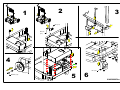
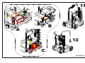
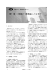
1094
014030000 Rev. 0
37
539
549
114
520
831
756
2
1
3
M8 (n° 2)
M8 x 40
(n° 2)
M8x16 (n°8)
4
M5 (n°8)
M10 (n°2)
M10x60 (n°2)
5
6
014030000 Rev. 0
7
A
A
B
9
8
B
10
014030000 Rev. 0
11
!
!
B
A
12
C
014030000 Rev. 0
TABLE OF CONTENTS
1
English
7
8
9
GENERAL
1.1
Summary of functions
GENERAL WARNINGS
SAFETY
3.1
Load the drum onto Viscotroll DC
3.2
Accidental oil spill
3.3
Disposal
3.4
Battery-charger safety
ASSEMBLY
4.1
Mechanical assembly of trolley and hydraulic part
4.2
Final electrical collections (fuse and battery-charger connector)
4.3
Charging the battery for the first time (setting the battery-charger)
USE
5.1
Purpose
5.2
Normal dispensing (with battery fully or partially charged)
5.3
Battery status
5.4
ON/OFF button
5.5
Setting and using the Timer for maximum dispensing time
MAINTENANCE
6.1
Maintenance of electrical parts
6.1.1
Recharging the battery
6.1.2.
Replacing the fuse
6.1.3
Replacing the battery
PROBLEMS AND SOLUTIONS
ELECTRICAL DIAGRAM
EXPLODED DIAGRAM OF PARTS
1
GENERAL
2
3
4
5
6
Viscotroll DC is a battery-powered oil-dispensing machine fitted with:
A
12 Vdc gear pump
B
pressure switch to automatically switch
the motor on and off during opening and closing
of the dispenser
C
flow meter with display (optional)
D
control circuit board
E
integrated battery-charger
Viscotroll DC is designed to hold and carry 1 drum of
lubricant oil of the following dimensions:
diameter:
58 cm
height:
88 cm
gross mass:
193 kg
C
English
3.4
RECHARGING
Electrical precautions: Dangerous voltages are present during the charging of the battery: only authorized
and qualified technical personnel should be allowed access to the unit.
- The battery-charger is for use with 1,2-120 Ah acid lead batteries.
Do not use it for anything else.
- Always wear protective eyewear and keep your face away from the battery when switching the unit
on and off.
- The batteries could release explosive gases during recharging. Ensure that there are no sparks or
flames near the battery.
- Ensure that there is adequate ventilation during recharging.
- Battery acid is corrosive. If the acid comes into contact with your skin or eyes, rinse with water
immediately. See a doctor.
- Do not recharge a frozen battery.
4
ASSEMBLY
4.1
Mechanical assembly of trolley and hydraulic part
To assemble, refer to the illustrated assembly instructions.
CONNECT SUCTION LINE AND DELIVERY LINE BY USING THE PROPER SEALING PASTE TO
GUARANTEE PRESSURE SEAL
BEFORE CONNECTING THE SUCTION HOSE TO THE PUMP, WET THE INSIDE OF THE PUMP
BODY WITH OIL THROUGH THE UPPER ELBOW. BEFORE CONNECTING, MAKE SURE THAT THE
PUMP IS COMPLETELY FULL OF OIL INSIDE.
4.2
Final electrical collections (fuse and battery-charger connector)
4.3
Charging the battery for the first time (setting the battery-charger)
See the illustrated assembly instructions.
3
GENERAL WARNINGS
5
The recharge process can be interrupted at any time by disconnecting the power supply
cable or by setting the battery-charger to standby mode. Always disconnect the power supply cable
from the socket before disconnecting the cables from the battery inside the vehicle.
UNPACKING
Viscotroll DC should be unpacked by 2 people, taking care to ensure that the package is in the
correct position as indicated by the arrows. Take out the trolley only after having fitted the handle
onto its base. Once the handle has been secured in accordance with the steps shown on the
assembly diagram provided, remove it completely from the packaging and carry on with the subsequent
assembly phases.
6
Alternate flashing of the recharge and maintenance indicator lights could be due to the
following:
• The recharge process has been interrupted following a loose connection or the battery
not operating.
• The battery has been sulphatized. Prolonged flashing lasting longer than 30 minutes
indicates that the battery is run-down and must be replaced.
• An interval exceeding 10 seconds between flashes indicates that the battery’s selfdischarge percentage is high and it may be necessary to replace it.
POWER SUPPLY - ASSEMBLY
First recharge time: In general, 6-8 hours are sufficient when charging for the first time
NOTE: Refer to chapter 6.1 for more information on replacing the battery
Disconnect the power during the entire assembly process. Do not connect the battery and
charger before assembly has been completed.
Protective Gloves: Prolonged contact with particularly aggressive oils could cause skin irritation.
It is recommended that you use protective gloves when dispensing the oil.
Vapours: When lubricant oil is dispensed, particularly in environments with high temperatures,
take precautions against the inhalation of harmful vapours (for example, using a mask).
Dispense oil in well-ventilated areas.
REPAIR
Service: the unit should be serviced by qualified personnel only. Please contact the dealer if you
require further information or assistance.
NB: FIT THE FUSE AS THE LAST STEP OF THE ASSEMBLY PROCESS, AS INDICATED IN THE
ASSEMBLY DIAGRAM.
3
SAFETY
3.1
Load the drum onto Viscotroll DC
Two people are always required to load the oil drum onto the Viscotroll DC trolley.
The manufacturer recommends that the drum be loaded according to the following procedure:
1 – Load the drum onto a “transpallet”-type platform truck, adjusting the height so that it is level with the
Viscotroll DC loading platform.
2 – Engage the brakes on the wheels of the Viscotroll DC and ensure that they are working properly.
3 – Move the transpallet closer to Viscotroll, so that they are facing each other.
4 – Engage the brakes on the wheels of the transpallet and ensure that they are working properly.
5 – With 2 people, one on either side of the transpallet, push the oil drum which will pass from the forks
of the transpallet to the Viscotroll DC trolley.
6 – Block the oil drum using the hook provided on the Viscotroll DC.
3.2
Accidental oil spill
In case of an accidental lubricant oil spill, cover the surface where the spill has occurred immediately
with sawdust or a similar material, which can quickly absorb the substance as well as make the area
safe against the risk of falling. Dispose of the oil-soaked substance in accordance with local regulations
in the country of use.
3.3
Disposal
If the station has to be demolished, the parts of which it is composed must be sent to companies that
specialize in the disposal and recycling of industrial refuse and, in particular: Dispose of the lubricant oil
in accordance with local regulations in the country of use.
is on it means the battery is being recharged,
4
No indication: if the voltage indicator is on but all the other indicator lights are off, it is
possible that the battery-charger has not been connected properly to the battery or that the battery
is faulty. Check the electrical socket. If there are problems: first check the connection between the
terminals and the battery-charger.
During the assembly and use of Viscotroll DC, follow the general safety warnings listed below:
Overheating: although the pump is fitted a pressure switch, always check that it stops when no
oil has been dispensed for more than 2 minutes. Stop the pump by pressing the ON/OFF button.
When the recharge indicator light
whereas the status light
indicates that the battery has been completely recharged. If the
voltage drops, the battery-charger sends a pulse to the battery. The duration of the pulse depends on
the intensity of the drop. The battery-charger can stay connected for several months. If the Viscotroll
DC is not used for long periods (months), ensure that the battery-charger is in “slow charge” mode, as
indicated by the symbol:
Summary of functions
Permitted uses: the unit must always be used for the purpose intended. Follow the instructions
contained in this manual.
use in case of emergency or to switch off once dispensing is finished
The machine is fitted with an ON/OFF button which allows you to enable or disable the pump, in
accordance with the table in paragraph 5.3.
NOTE: if the red LED is on, the pressure of the red button has no effect on the
operation of the pump.
For example, it is necessary to disable the pump if there is no oil inside the drum or if there are leaks
in the pipes, which makes it necessary to carry out maintenance on them (the pump would therefore
always be on because there is never any pressure in the pressure switch).
5.5
Setting and using the Timer for maximum dispensing time
The Timer for maximum dispensing time, which can be
removed and adjusted by means of the DIP-SWITCH
and which has times of 10, 20 and 30 minutes that
can be selected (see table 2), blocks the pump if the
dispensing time exceeds the maximum time that has
been set.
5
USE
5.1
Purpose
The Viscotroll DC station is suitable for professional use, to transfer oil with a maximum viscosity of
1100 cSt, which can be assimilated to SAE 10W-40 type oil at an operating temperature of 7°C and SAE
80W-90 type oil at an operating temperature of 14°C.
5.2
OFF
ON
ON
ON
1
OFF
ON
OFF
OFF
2
Battery status
Battery status LED
Motor status LED
Green LED
Yellow LED
Red LED
On
Off
Off
Flashing
Off
On
Not conclusive
Not conclusive
Status
On
On
Battery full. Dispensing possible
Battery half-full. Dispensing possible. We
recommend that the the battery be charged.
Off (due to the battery Battery low. Dispensing
voltage being too low) impossible. Necessary battery charge
Off due to:
If the pump is switched off by pressing the
- manually pressing
ON/OFF button or if the timer for maximum
the ON/OFF button
dispensing time has intervened, the yellow
or
LED goes off. Dispensing impossible even
- due to the intervention if the battery is fully charged. Press the
of the TIMER
ON/OFF button, switching the yellow LED
on again.
SWITCH S1
OFF
OFF
ON
OFF
3
6
MAINTENANCE
6.1
Maintenance of electrical parts
OFF
OFF
OFF
OFF
4
TIMER
DISABLED
10 Minutes
20 Minutes
30 Minutes
6.1.1
Recharging the battery
6.1.2.
Replacing the fuse
6.1.3
Replacing the battery
From the second recharge onwards, to recharge the battery all you have to do is insert the plug of the
battery-charger in an electrical socket. If the battery provided (44Ah) is completely empty, the duration of
the recharge should be approximately 15 hours.
If the fuse blows, first check the reasons that caused this, then replace it with another one of the same
type, a 30A blade fuse (light green). For further details, refer to the attached assembly diagram. We
recommend that spare parts from the manufacturer be used.
When the battery does not work anymore, replace it with another one of the same type, TRACTION
GEL, with the same power 44AH. We recommend that spare parts from the manufacturer be used.
Connect the red wire to the positive pole of the battery and the black one to the negative pole. For the
battery replacement procedure, refer to the attached assembly diagram (see pict. A, B, C).
7
PROBLEMS AND SOLUTIONS
Problem
Possible cause
When you press the trigger of Batter run-down, red LED
the nozzle,
constantly on
the pump does not switch on.
Motor disabled
(Yellow LED off) due to:
- manually pressing the ON/OFF
button or
- due to the intervention of the
TIMER
Normal dispending (with battery fully or partially charged)
Viscotroll DC is fitted with an electronic circuit board that controls the status of the battery and, by
means of 2 LEDs (green and red), signals when it needs to be recharged.
A third LED (yellow) indicates the status of the motor (ON or OFF).
The status of this LED depends on:
*
the charge of the battery;
*
the user manually pressing the ON/OFF button;
*
the operation of the timer for maximum dispensing time
When the yellow LED is off the pump motor will not start. The red button must be pressed to restart the
pump and for the yellow LED to light up again.
Below is a table showing the status of the LEDs in relation to the status of the system:
VISCOTROLL
DC
table 2
To access the timer, open the electrical box in which the electronic circuit
board is found loosening the 4 screws. The timer begins to operate each
time the pump is switched on and, if enabled, it allows the pump to
operate for the maximum time that has been set.
This function is particularly useful in case of breakage or pressure loss
in the hydraulic pipes when the operator is not present. The timer would
stop the pump before any damage is caused to Viscotroll DC.
To restart the pump after it has been stopped by the timer if the red LED
is not on, the red button must be pressed.
The yellow LED goes on to indicate that the pump can start dispensing
again.
To dispense the oil (with battery fully or partially charged), it is sufficient to press the trigger of the
dispensing nozzle. The pump will start automatically and the oil begins to flow. To stop the oil flow,
simply release the trigger of the nozzle: the pressure switch is activated after a few seconds and the
pump switches off automatically.
5.3
M0136 rev. 1
The default setting is shown in the following diagram,
Timer active, 10 minutes maximum dispensing.
2
Once you have checked that the battery cables are connected correctly, connect the
power supply cable to the socket to start recharging. If the battery cables are not connected correctly,
the integrity of the battery-charger will be guaranteed by the polarity inversion switch. In this case, the
fault indicator light will be on and the recharge process will have to be restarted.
D
USE
ON/OFF button
1
Set the appropriate voltage for the battery by pressing the “MODE” button on the mode
selector until the indicator light that corresponds to the symbol goes on
A
B
Viscotroll DC allows you to dispense oils at any time simply by pressing the trigger on the delivery nozzle.
The pump will start automatically and the oil begins to flow. To stop the oil flow, simply release the trigger of
the nozzle: the pressure switch is activated after a few seconds and the pump switches off automatically.
Viscotroll DC is fitted with an electronic circuit board that controls the status of the battery and, by means
of a LED, signals when it needs to be recharged. For more details, see the paragraphs that follow. The
machine is fitted with an ON/OFF button which enables or disables motor operation, and with a timer for
maximum dispensing time.
2.
5.4
NOTE:
Everything mentioned in this paragraph is relative to the battery charger and the
indicator lights present on it. These indicator lights must NOT be confused with those on the
electronic circuit board, which are described in paragraph 5.3
E
1.1
English
Battery-charger safety
The pump does not switch off
a few seconds after having
released the trigger
Possible solution
recharge the battery
press the ON/OFF button to
bring it back to ON (yellow
LED on)
30A fuse blown
replace the fuse following the
instructions
The pressure switch does not
intervene
contact the manufacturer
Mosfet fault
contact the manufacturer
The pressure switch does not
intervene
check that the oil drum
is not empty
The pressure switch does not
intervene and the drum is not
empty
contact the manufacturer
The pump does not switch off
Electronic circuit board faulty or
after 10 (or 20 or 30 if the default MOSFET circuit board shortsettings have been changed) circuiting
minutes
of
uninterrupted
operation
f, when you press the ON/OFF
button, the pump switches
off, the problem is with the
MOSFET circuit board.
Contact the manufacturer
The battery does not stay
charged
replace the battery
8
battery worn
ELECTRICAL DIAGRAM
table 1
IMPORTANT: During pump operation, the electronic circuit board suspends the battery charge
level control to allow for complete dispensing to take place. Therefore, a situation may arise
in which you start off with the yellow and green LEDs on and, once the dispensing is finished
(particularly if it is very long), the yellow and green LEDs go off and the red LED goes on. Due to its nature,
the battery will recover some charge after a while, the red LED will begin to flash and the yellow LED will
go on allowing you to dispense more oil. It is nevertheless recommended that the battery be charged as
soon as possible.
Bulletin M0136 rev. 1
SOMMARIO
1
Italiano
7
8
9
GENERALITA’
1.1
Descrizione sommaria delle funzioni
AVVERTENZE GENERALI
SICUREZZA
3.1
Caricare il fusto su Viscotroll DC
3.2
Spandimento accidentale di olio
3.3
Smaltimento
3.4
Sicurezza del caricabatteria
ASSEMBLAGGIO
4.1
Assemblaggio meccanico carrello e parte idraulica
4.2
Connessioni elettriche finali (fusibile e connettore caricabatteria)
4.3
Prima carica della batteria (con settaggio del caricabatteria)
UTILIZZO
5.1
Destinazione d’uso
5.2
Erogazione normale (batteria carica o semi-scarica)
5.3
Stati di batteria
5.4
Tasto ON/OFF
5.5
Utilizzo e configurazione del Timer di tempo massimo di erogazione
MANUTENZIONE
6.1
Manutenzione parti elettriche
6.1.1
Ricarica della batteria
6.1.2.
Sostituzione del fusibile
6.1.3
Sostituzione della batteria
PROBLEMI E SOLUZIONI
SCHEMA ELETTRICO
ESPLOSO DELLE PARTI
1
GENERALITA’
2
3
4
5
6
Italiano
3.4
Italiano
Sicurezza del caricabatteria
RICARICARE
Precauzioni elettriche: Durante il caricamento delle batterie, sono presenti tensioni pericolose.
l’accesso all’unità deve essere consentito al solo personale tecnico qualificato ed autorizzato.
- Il caricabatterie è destinato alla ricarica di batterie al piombo acido da 1,2-120 Ah.
Non utilizzarlo per altre finalità.
- Indossare sempre occhiali protettivi e allontanare il volto dalla batteria durante le fasi di
accensione e spegnimento.
- Durante la ricarica le batterie possono emettere gas esplosivi. Evitare fiamme e scintille in
prossimità della batteria.
- Assicurare un’adeguata ventilazione durante la ricarica.
- L’acido delle batterie è corrosivo. Qualora l’acido venga a contatto con la pelle o con gli occhi,
sciacquare immediatamente con acqua. Consultare il medico.
- Non ricaricare una batteria congelata.
4
ASSEMBLAGGIO
4.1
Assemblaggio meccanico carrello e parte idraulica
Per l’assemblaggio, fare riferimento alle istruzioni di montaggio illustrate.
COLLEGARE LE TUBAZIONI IN ASPIRAZIONE ED IN MANDATA UTILIZZANDO UN ADEGUATO
SIGILLANTE PER GARANTIRE LA TENUTA IN PRESSIONE.
PRIMA DI COLLEGARE IL TUBO DI ASPIRAZIONE ALLA POMPA, È NECESSARIO RIEMPIRE
COMPLETAMENTE QUEST’ULTIMA CON OLIO LUBRIFICANTE, ATTRAVERSO IL GOMITO
SUPERIORE. PRIMA DI ESEGUIRE IL COLLEGAMENTO, ASSICURARSI CHE LA POMPA SIA
COMPLETAMENTE PIENA DI OLIO.
4.2
Connessioni elettriche finali (fusibile e connettore caricabatteria)
Viscotroll DC è un apparecchio per l’erogazione dell’olio alimentato a batteria dotato di:
4.3
Prima carica della batteria (con settaggio del caricabatteria)
A
B
NOTA:
Tutto ciò che viene riportato nel presente paragrafo, è relativo al caricabatteria ed alle
indicazioni luminose su di esso riportate. Tali indicazioni luminose NON sono da confondere con
quelle della scheda elettronica, descritte al paragrafo 5.3
C
D
E
Pompa ad granaggi alimentata a 12 Vdc
pressostato per l’accensione
e lo spegnimento automatico del
motore all’apertura e chiusura
dell’erogatore
contalitri con display (optional)
scheda elettronica di controllo
caricabatteria integrato
Viscotroll DC è progettato per contenere e trasportare
nr. 1 fusto di olio lubrificante delle seguenti dimensioni:
diametro:
58 cm
altezza:
88 cm
peso lordo: 193 kg
Vedere le istruzioni di montaggio illustrate.
C
A
B
3
Descrizione sommaria delle funzioni
AVVERTENZE GENERALI
DISIMBALLARE
Eseguire il disimballo di Viscotroll DC in 2 persone, osservando e rispettando l’orientamento
dell’imballo, indicato con le frecce. Estrarre il carrello, solo dopo avere eseguito il montaggio del
maniglione sulla sua base. Una volta fissato il maniglione, secondo le fasi illustrate nello schema
di montaggio in allegato al prodotto, estrarlo totalmente dal suo imballo, procedendo con le successive
fasi di assemblaggio.
ALIMENTARE - ASSEMBLARE
Staccare l’alimentazione per tutta la durata dell’assembleggio. Non connettere la batteria ed il
caricabatterie prima di avere terminato l’assemblaggio.
UTILIZZARE
Usi consentiti: l’unità deve essere usata secondo le finalità previste. Seguire le istruzioni riportate
nel presente manuale.
Surriscaladamento: anche se la pompa è provvista di pressostato, assicurarsi che si arresti
qualora l’olio non venga erogato per oltre 2 minuti. Arrestare la pompa agendo sul tasto ON/OFF
Guanti Protettivi: Il contatto prolungato con olii particolarmente aggressivi, può provocare
irritazioni. Durante l’erogazione, è consigliabile l’uso di guanti protettivi.
Vapori: Durante l’erogazione di olio lubrificante, specialmente in condizioni ambientali
caratterizzati da alte temperature, proteggersi dall’eventualità di inalazione di vapori nocivi alla
salute (ad esempio con mascherina). Eseguire erogazioni di olio in ambiente ventilato.
RIPARARE
Assistenza: l’assistenza sull’unità deve essere eseguita solo da personale autorizzato. Per ogni
eventuale esigenza, rivolegrsi direttamente al rivenditore.
NB: INSERIRE IL FUSIBILE COME ULTIMO PASSO DELL’ASSEMBLAGGIO, COME INDICATO
NELLO SCHEMA DI MONTAGGIO.
3
SICUREZZA
3.1
Caricare il fusto su Viscotroll DC
Per eseguire l’operazione di carico del fusto di olio sul carrello di Viscotroll DC, è sempre necessaria la
presenza di 2 persone.
Il costruttore, consiglia di caricare il fusto seguendo il procedimento illustrato di seguito:
1 - Caricare il fusto su un trasportatore di tipo “transpallet” regolandolo ad una altezza pari al piano di
carico di Viscotroll DC.
2 - Azionare i freni sulle ruote di Viscotroll DC ed assicurarsi della loro efficacia.
3 - Avvicinare il transpallet a Viscotroll, in modo che risultino esattamente uno di fronte all’altro.
4 - Azionare i freni sulle ruote del transpallet ed assicurarsi della loro efficacia
5 - Con la presenza di 2 persone posizionate sui 2 lati del transpallet, spingere il fusto di olio, che in
questo modo, passerà dalle forche del transpallet al carrello di Viscotroll DC.
6 - Bloccare il fusto di olio con il gancio presente su Viscotroll DC.
Spandimento accidentale di olio
In caso di accidentale spandimento di olio lubrificante, provvedere al più presto a coprire la superficie
di pavimento interessato alla fuoriuscita con segatura o materiale analogo, in grado di garantire un
rapido assorbimento della sostanza oltre a renderla sicura al rischio di cadute. Smaltire tale materiale
impregnato di olio, secondo le normative in vigore nel paese di utilizzo.
3.3
Smaltimento
5.5
In caso di demolizione della stazione, le parti di cui è composta devono essere affidate a ditte
specializzate nello smaltimento e riciclaggio dei rifiuti industriali. Smaltire l’olio lubrificante, secondo le
normative in vigore nel paese di utilizzo.
La spia di ricarica
L’impostazione di fabbrica è quella mostrata nella
figura seguente, Timer attivo, 10 minuti di erogazione
massima.
OFF
ON
ON
ON
1
2
OFF
ON
OFF
OFF
SWITCH S1
OFF
OFF
ON
OFF
3
OFF
OFF
OFF
OFF
4
TIMER
DISABILITATO
10 Minuti
20 Minuti
30 Minuti
tabella 2
Per accedere al timer, è necessario aprire la cassetta elettrica ove si
trova la scheda elettronica, svitandone le 4 viti.
Il timer entra in funzione tutte le volte che la pompa si accende e,
se abilitato, permette alla pompa di funzionare per il tempo massimo
selezionato.
Questa funzione è particolarmente utile nel caso di rottura o perdita di
pressione nei condotti oleodinamici mentre l’operatore non è presente.
Il timer fermerebbe la pompa in tempo perché Viscotroll DC non subisca
danni.
Per riabilitare la pompa dopo che è stata disabilitata dal timer se il led
rosso non è acceso, occorre premere il pulsante rosso.
L’accensione del led giallo conferma che la pompa è di nuovo abilitata
ad erogare.
accesa indica che la ricarica è in corso, mentre quella di
6
4
Nessuna indicazione: se l’indicatore di tensione è acceso ma tutte le altre spie sono
spente, è possibile che il caricabatterie non sia stato collegato correttamente alla batteria oppure
che la batteria sia difettosa. Controllare la presa elettrica. In caso di problemi: verificare innanzitutto il
collegamento tra i morsetti della batteria e il caricabatterie.
Dalla seconda ricarica in poi, per effettuare la ricarica della batteria, basterà inserire la spina del
caricabatteria in una presa di corrente. La durata della ricarica della batteria fornita (44Ah), nel caso fosse
completamente scarica, è di 15 ore circa.
5
La ricarica può essere interrotta in qualsiasi momento scollegando il cavo di alimentazione
oppure portando il caricabatterie in modalità stand-by. Scollegare sempre il cavo di alimentazione dalla
presa prima di scollegare i cavi dalla batteria nel veicolo.
Nel caso in cui il fusibile si bruci, verificare dapprima le cause che ne hanno determinato la rottura, quindi
sostituirlo con uno dello stesso tipo, fusibile a lama da 30A (verde chiaro). Per i dettagli, fare riferimento
allo schema di montaggio in allegato. Si consiglia di utilizzare ricambi del costruttore.
6
Il lampeggio alternato della spia di ricarica e di quella di manutenzione è dovuto a uno dei
seguenti motivi:
• La ricarica è stata interrotta a seguito di un collegamento allentato o al mancato funzionamento della
batteria.
• La batteria si è solfatizzata. Un lampeggio prolungato per più di30 minuti indica che la batteria è
esausta e deve essere sostituita.
• Un intervallo superiore a 10 secondi tra un lampeggio e l’altro indica che la percentuale di
autoscaricamento della batteria è elevata e potrebbe essere necessario effettuarne la sostituzione.
Quando la batteria risulta inefficiente, sostituirla con una dello stesso tipo, GEL TRAZIONE e della stessa
potenza, 44AH. Si consiglia di utilizzare ricambi del costruttore.
Collegare il filo rosso al polo positivo della batteria e quello nero al polo negativo. Per il procedimento di
sostituzione batteria, fare riferimento allo schema di montaggio in allegato (figg. A, B, C).
NOTA: Per la sostituzione della batteria, fere riferimento al capitolo 6.1.1
5
UTILIZZO
5.1
Destinazione d’uso
5.2
Erogazione normale (batteria carica o semi-scarica)
MANUTENZIONE
6.1
Manutenzione parti elettriche
6.1.1
Ricarica della batteria
6.1.2.
Sostituzione del fusibile
6.1.3
Sostituzione della batteria
7
Problema
Possibile causa
Possibile soluzione
Azionando il grilletto della
pistola, la pompa non si
accende.
Batteria scarica, led rosso
acceso fisso.
ricaricare la batteria
Led Verde
Led Rosso
Acceso
Spento
Spento
Lampeggiante
Spento
Acceso
Non
determinante
Non
determinante
Led Stato Motore
Stato
Led Giallo
Acceso
Acceso
Batteria carica. Erogazione possibile
Batteria semiscarica. Erogazione possibile. Si
consiglia la ricarica della batteria.
Spento (a causa della Batteria scarica. Erogazione impossibile. Necestensione di batteria troppo saria carica della batteria
bassa)
Spento a causa di:
Se agendo sul pulsante ON/OFF si porta la
- una azione manuale sul pompa in OFF, oppure se è intervenuto il timer
pulsante ON/OFF
di tempo massimo di erogazione, il Led giallo
oppure
si spegne. Erogazione impossibile anche con
- per intervento del batteria carica.
TIMER
Premere il pulsante ON/OFF, riaccendendo il
led giallo.
tabella 1
ATTENZIONE: Durante il funzionamento della pompa, la scheda elettronica sospende il controllo
del livello di carica della batteria, per permettere di effettuare l’erogazione completa.
Può verificarsi quindi il caso che si parta con i led verde e giallo accesi e, alla fine della erogazione,
specie se molto lunga, il led verde si spenga, si spenga il led giallo e si accenda il led rosso.
La batteria, per sua natura, dopo qualche tempo recupererà un po’ di carica, il led rosso si metterà a
lampeggiare e il led giallo si accenderà consentendo una nuova erogazione. E’ comunque consigliabile
ricaricare la batteria al più presto.
DICHIARAZIONE DI CONFORMITA’
premere pulsante ON/OFF per
riportare in stato ON (led giallo
- una azione manuale sul pulsante acceso)
Il sottoscritto, rappresentante il costruttore
PIUSI S.p.A. - 46029 Suzzara - Mantova - ITALY
ON/OFF oppure
- per intervento del TIMER
Stati di batteria
Led Stato batteria
10653 : 2003 – Technical documentation – Quality of the product technical documentation
10893 : 2000 – Product technical documentation – instructions for use – Sections and order of the content
Motore inibito (Led giallo
spento) a causa di:
Per effettuare una erogazione (in condizioni di batteria carica o semi-scarica) è sufficiente agire sul
grilletto della pistola di erogazione. Automaticamente partirà la pompa e l’erogazione ha inizio. Per
terminare l’erogazione basta semplicemente rilasciare il grilletto della pistola: dopo pochi istanti interviene
il pressostato e la pompa si spegne automaticamente.
Viscotroll DC è dotato di una scheda elettronica che controlla lo stato della batteria e, attraverso una
segnalazione a 2 led (verde e rosso), indica quando è necessario effettuare la ricarica.
Un terzo led (giallo) indica lo stato di abilitazione del motore (ON o OFF).
Lo stato di tale led dipende:
∗
dalla carica della batteria;
∗
dall’azione manuale dell’utente sul pulsante ON/OFF;
∗
dal funzionamento del timer di tempo di erogazione massimo.
Quando il led giallo è spento il motore della pompa non parte. Occorre premere il pulsante rosso per
riabilitare la pompa e riaccendere il led giallo.
Viene riportata una tabella con lo stato dei led in relazione allo stato del sistema:
Il presente manuale è stato redatto secondo le seguenti norme:
10653 : 2003 - Documentazione tecnica - Qualità della documentazione tecnica di prdootto
10893 : 2000 - Documentazione tecnica di prodotto - istruzioni per l’uso - Articolazione e ordine espositivo del contenuto.
This manual has been drafted according to the following norms:
PROBLEMI E SOLUZIONI
La stazione Viscotroll DC, è idonea ad uso professionale per operazioni di travaso di olio con viscosità
massima di 1100 cSt , assimilabile ad olio di tipo SAE 10W-40 a temperatura di esercizio di 7°C e SAE
80W-90 a temperatura di esercizio di 14°C
5.3
(EXPLODED DIAGRAM OF PARTS)
Utilizzo e configurazione del Timer di tempo massimo di erogazione
stato
segnala che la ricarica della batteria è stata completata. In caso di calo della tensione,
il caricabatterie invia un impulso alla batteria. La durata dell’impulso dipende dall’intensità del calo.
Il caricabatterie può rimanere collegato per diversi mesi. Nel caso in cui Viscotroll DC non venga
utilizzato per lunghi periodi (mesi), assicurarsi di impostare il caricabatterie in modalità di “carica lenta”,
segnalato dal simbolo:
Tempo di prima ricarica : Per la prima carica in generale sono sufficienti 6-8 ore
ESPLOSO DELLE PARTI
Il Timer di tempo massimo di erogazione, escludibile
e regolabile tramite DIP-SWITCH, con tempi
selezionabili tra 10, 20 e 30 minuti, (vedi tabella 2)
blocca la pompa nel caso il tempo di erogazione superi
il tempo massimo impostato.
D
Durante l’assemblaggio e l’uso di Viscotroll DC, osservare le avertenze generali di sicurezza elencate di seguito:
3.2
utilizzo in caso di emergenza o come spegnimento a fine erogazione
Italiano
9
L’apparecchio è dotato di un pulsante di ON/OFF che permette di abilitare o disabilitare la pompa, in
accordo con la tabella del paragrafo 5.3.
NOTA: se il led rosso è acceso, la pressione del pulsante rosso non ha alcun
effetto sull’abilitazione della pompa.
Ad esempio, si rende necessario disabilitare la pompa qualora l’olio nel fusto venisse a mancare oppure
se ci sono perdite nei tubi, che rendono necessaria la manutenzione degli stessi (la pompa sarebbe così
sempre accesa poiché il pressostato non va mai in pressione).
2
Una volta verificato il corretto collegamento dei cavi della batteria, collegare il cavo di
alimentazione alla presa per iniziare la ricarica. Se i cavi della batteria non sono collegati correttamente,
l’integrità di batteria e caricabatterie sarà garantita dall’interruttore di inversione della polarità. In tal
caso, l’indicatore di guasto
risulterà acceso e sarà necessario riavviare la ricarica.
Viscotroll DC consente di effettuare erogazioni di olii in qualunque momento semplicemente agendo
sul grilletto della pistola di erogazione. Automaticamente partirà la pompa e l’erogazione ha inizio.
Per terminare l’erogazione basta semplicemente rilasciare il grilletto della pistola: dopo pochi istanti
interviene il pressostato e la pompa si spegne automaticamente.
Viscotroll DC è dotato di una scheda elettronica che controlla lo stato della batteria e attraverso una
segnalazione a led, indica quando è necessario effettuare la ricarica. I dettagli sono riportati nei
paragrafi successivi.
L’apparecchio è dotato di un pulsante di ON/OFF che abilita o disabilita il funzionamento del motore, e
di un timer di tempo massimo di utilizzo.
2.
Tasto ON/OFF
1
Impostare la tensione appropriata per la batteria premendo il tasto “MODE” del selettore
della modalità fino all’accensione della spia corrispondente al simbolo
E
1.1
5.4
Fusibile da 30A bruciato
sostituire fusibile seguendo le
istruzioni.
Il pressostato non interviene
contattare il produttore
Guasto del Mosfet
contattare il produttore
La pompa non si spegne pochi
secondi dopo aver rilasciato il
griletto
Il pressostato non interviene
verificare che il fusto dell’olio
non sia vuoto
Il pressostato non interviene a
fusto non vuoto
contattare il produttore
La pompa non si spegne
dopo 10 ( o 20 o 30 se si sono
modificate le impostazioni di
fabbrica) minuti ininterroti di
funzionamento
Scheda elettronica guasta
o scheda MOSFET in corto
circuito
Se azionando il tasto ON/OFF la
pompa si spegne, il problema è
nella scheda MOSFET.
Contattare il produttore
La batteria non mantiene la
carica
batteria usurata
sostituire la batteria
8
DICHIARA
che l’apparecchiatura descritta in appersso
Descrizione: VISCOTROLL DC
Modello: F00263200-F00263210-F00263220-F00263230
è conforme alle seguenti direttive:
98/37/CE Direttiva macchine
73/23/CE Direttiva Bassa Tensione
ed alle seguenti normative internazionali (e loro successive varianti):
EN 809-2000 Pompe e gruppi di pompaggio per liquidi
EN 13167-1 (2004) Requisiti costruttivi di sicurezza e prestazioni di stazioni di distribuzione con contatori.
EN ISO 12100 (2005) Sicurezza del macchinario - Concetti fondamentali; principi fondamentali di progettazione
parte 1: Terminologia medodologia di base (ISO EN 12100-1 - ex EN 292-1)
parte 2: Principi tecnici (ISO EN 12100-2 - ex EN 292-2)
Il presidente Otto Varini
Suzzara 01/09/2005
DECLARATION OF CONFORMITY
The undersigned, representing the manufacturer
PIUSI S.p.A. - 46029 Suzzara - Mantova - ITALY
SCHEMA ELETTRICO
CERTIFIES
that the equipment described below:
Description: VISCOTROLL DC
Model: F00263200-F00263210-F00263220-F00263230
complies with the following directives:
98/37/CE Machine directive
73/23/CE Low Voltage Directive
and the following international standards (and subsequent amendments):
EN 809-2000 Pumps and pumping units for liquids
EN 13167-1 (2004) Safety manufacturing requirements and performance of distribution stations with flow
meters.
EN ISO 12100 (2005) Machine safety- Fundamental concepts, fundamental principles of design
part 1: Basic methodology terminology (ISO EN 12100-1 - ex EN 292-1)
part 2: Technical principles (ISO EN 12100-2 - ex EN 292-2)
Otto Varini, Chairman
Suzzara 01.09.05