1
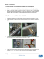
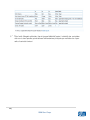
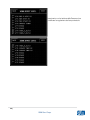
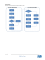
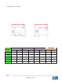
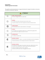
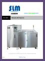
[Pick the date] www.slmcoop.com ECO-WIZ Manuale Wet System Copyright (C) Eco-Wiz Group Pte Ltd | www.eco-wiz.com Rev 1.1 SLM Soc. Coop. Proprietary Notice This document contains proprietary information that is protected by copyright. No part of this document may be photocopied, reproduced or translated to another language in whole or in part without prior written permission from; Eco-Wiz Group Pte Ltd No.1 Bukit Batok Crescent WCEGA Plaza #09-58 Singapore 658064 www.eco-wiz.com Eco-Wiz Group (EWG) reserves the right to make equipment changes and improvements that may not be reflected in this document. Portions of this document may have been updated to include the latest version, if applicable. Eco-Wiz Group makes no warranty of any kind with regard to this material, including but not limited to, the implied warranties of merchantability and fitness for a particular purpose. We recommend that this document be read in its entirety before any attempt is made to operate the equipment. For more information about Eco-Wiz Group line of products, visit our web site at: www.eco-wiz.com 2|Page SLM Soc. Coop. Contenuti Contents ECO-WIZ WET MODULE .......................................................................................................................... 6 Eco-Wiz Modulo Wet pag. 6 SYSTEM FEATURES.................................................................................................................................. 6 Caratteristiche del Sistema pag. 6 1-1 Food Waste Decomposition Process ........................................................................................ 6 Processo di decomposizione del rifiuto alimentare pag. 6 1-1 1-1.1 1-1.1 Bacterial Formula "Eco-Wiz Microbes®" ........................................................................... 6 Formula batterica “Eco-Wiz Microbi” pag. 6 1-1.2 1-1.2 ECO-WIZ Ecological Benefits ............................................................................................. 7 Benefici ecologici pag. 7 1-1.3 1-1.3 ECO-WIZ Economic Benefits ............................................................................................. Benefici economici pag. 77 1-2 1-2Prestazioni ECO-WIZ del WetSistema System Performance Features ........................................................................... Eco-Wiz Wet pag. 88 OPERATING INSTRUCTIONS Istruzioni operative del Modulo– Wet Wet Module............................................................................................ pag. 88 2-1 2-1Utilizzo Using the Hatch ................................................................................................................... delMain portello principale pag. 88 2-2 2-2Procedura Microbes Inoculation Procedures Module)......................................................................... per l’inserimento dei (Wet batteri pag. 99 2-3 pulire esternamente il modulo Wet pag. 99 2-3Come Cleaning Instructions – Exterior Only ........................................................................................... 2-4 puòDon’ts e cosaforNON puòWet essere introdotto nel modulo Wet Eco-Wiz pag. 10 2-4Cosa Do’s and Eco-Wiz Module ................................................................................. 10 Manuale di installazione Installation Guidelines .......................................................................................................................... 11 3-1 Caratteristica delsite sitorequirement di installazione pag. 11 3-1 Installation for Eco-Wiz Wet Module ............................................................. 11 3-2 Installazione del modulo Wet nel Sistema Eco-Wiz pag. 11 3-2Installing the Eco-Wiz Wet System ............................................................................................. 11 Manuale per l’utilizzo dello schermo Touch Screen PLC pag. 13 User’s Guide to PLC Touch Screen Controls for Wet Module .............................................................. 13 Manutenzione del Sistema Wet pag. 19 System Service & Maintenance ............................................................................................................ 19 5-1 Controlli settimanali pag. 19 5-1 Weekly Site Inspection ............................................................................................................... 19 5-2 Controlli trimestrali pag. 19 5-2 Quarterly System Service & Maintenance ................................................................................. 19 5-3 Risoluzione dei problemi pag. 20 5-3 Troubleshooting ........................................................................................................................ 20 3|Page SLM Soc. Coop. Troubleshooting Procedures/Steps: – ........................................................................... 5-4 5-4 System Procedure per la risoluzione dei problemi pag.2121 Extracting of impurities/foreign objects ............................................................................. 5-4.1 5-4-1 Estrarre impurità o oggetti estranei pag.2121 5-4.2 5-4-2 Estrarre e sostituire le lame danneggiate / guasto del rimescolatore pag.2222 To extract and replace damage / broken grinder blades .................................................... Procedure di estrazione e riparazione danno/rottura Procedures to extract and replacedel damage / broken grinder blades (For Grinder Fitted System) delle lame.................................................................................................................................................. del rimescolatore pag.2222 Light Tower Indicator ..................................................................................................... 5-5 5-5 System Sistema di indicazioni luminose a torretta sulla macchina (semaforo) pag.2222 Sequence identify the cause forlesystem Sequenza delle to procedure perroot identificare cause drum condition to be wet (For all system) ................................................................................................................................................................ delle rotture nel tamburo per tutti sistemi pag.2323 Procedure to extract excessinfood waste out from system drum (For all system) ................ Procedure per estrarre il carico eccesso pag.2323 Identifying Problemi tecnicivarious type of system technical failure (For all system) ...................................... pag.2424 ECO-WIZ MEMBRANE BIO-REACTOR (MBR) MODULE ......................................................................... Sistema MBR (Bioreattore) pag.2525 Difetti di sistema pag.2525 SYSTEM FEATURES................................................................................................................................ 1-1 1-1 Descrizione del modulo MBR pag.2525 MBR Module Description ........................................................................................................ 1-2 1-2 Flusso del processo pag.2626 Process Flow........................................................................................................................ Componenti fondamentali della macchina pag.2727 Machine Key Components............................................................................................................ 1-3 1-3 Disposizione e dimensione del serbatoio pag. 27 Tank Arrangement and size .................................................................................................... 27 1-4 2-1 1-4 Specifiche della macchina pag. 28 Machine Specification ............................................................................................................. 28 Procedure per l’installazione pag. 28 2-1 Installation procedure ................................................................................................................ 28 2-1-1 Operazioni normali pag. 29 2-1-1 Normal Operation ............................................................................................................... 29 3-1 Pannello di controllo pag. 29 3-1 Control Panel Display ................................................................................................................. 29 3-2 Schermo Touch Screen pag. 30 3-2 Touch Screen Display ................................................................................................................. 30 4|Page SLM Soc. Coop. Manual Mode .................................................................................................................... 3-3 3-3 MBR Manuale di utilizzo dell’unità MBR pag.3434 Part List............................................................................................................................. 3-4 3-4 Spare Lista componenti di scorta pag.3939 Appendice pag.4040 Appendix A A: .......................................................................................................................................... Processo di funzionamento del Sistema Wet Eco-Wiz pag.4040 Flow Chart of Eco-Wiz Wet System ...................................................................................................... Appendice pag.4141 Appendix B B:- ......................................................................................................................................... Funzioni operative del Sistema Wet Eco-Wiz pag.4143 ECO-WIZ Wet System Operational Features ........................................................................................ Appendice C pag. 43 Appendix C:- ......................................................................................................................................... 43 Appendice D pag. 44 Appendix D:- ......................................................................................................................................... 44 Istruzioni generali di sicurezza pag. 44 General Safety Instructions .................................................................................................................. 44 5|Page SLM Soc. Coop. Eco-Wiz modulo ECO-WIZ WETWet MODULE SYSTEM FEATURES 1-1 di decomposizione del rifiuto alimentare 1-1Processo Food Waste Decomposition Process IlThe Modulo Wet Eco-Wiz è totalmente autosufficiente, con alimentazione continua, è progettato Eco-Wiz Wet Module is a totally self-contained, continual feed, organic waste disposal system designed to biologically convert solid food waste into liquid. Using a per convertire in maniera biologica i rifiuti di origine alimentare in acqua. process perfected by nature, it decomposes food waste into a nutrientricco richdiliquid thatnuis Perfezionando un processo naturale, lo scarto si decompone in un liquido prodotti virtually odor free, is safely of through existing sewage treatment facilities trienti, inodore e puòand essere avviatodisposed allo scarico. or septic systems. La funzione primaria del Modulo Wet Eco-Wiz è quello di accelerare la decomposizione naturale The primarylivelli function the Eco-Wiz Wet Module is (Fig. to accelerate the natural mantenendo ottimali of di aerazione, umidità e temperatura 2-1). Controllando queste decomposition process by maintaining optimal levels of aeration, moisture, and condizioni, i microrganismi brevettati decompongono gli scarti alimentari molto più velocemente temperature (see Figure 2-1). Under these controlled conditions, the US Pat. Pending, che naturalmente (Fig.2-2) senza contaminare il suolo e l’acqua del sottosuolo. microorganisms safely decompose the food waste at much faster rate than natural Ildecomposition sistema Eco-Wiz decomporre in maniera sicura e rapida ogni tipo di rifiuto The alimentare (seepuò Figure 2-2); without soil and ground water contamination. Ecocome: frutta, verdura, carne cruda e cotta, pesce, pollo e latticini. Wiz Wet System can safely and quickly decompose any kind of food waste including: vegetable/fruit scraps, raw and cooked meats, fish, poultry, and dairy products. Figura 1-1 ?-1 Processo di decomposizione Eco-Wiz Figure Eco-Wiz Decomposition Process 1-1.1 batterica “Eco-Wiz Microbi” 1-1.1 Formula Bacterial Formula "Eco-Wiz Microbes®" In Eco-Wiz Wet Module mechanically controlled, decomposition process, bacteria play Ithe batteri rivestono un ruolo processo di decomposizione che avviene Modulo most important role.importante Different nel bacteria produce unique enzymes, whichnelare the Wet Eco-Wiz a parametri controllati. protein catalysts responsible for the metabolism of organic waste. Eco-Wiz Group Differenti battericarefully producono enzimi unici, sonoeffective le proteine catalizzatrici loro (EWG) has selected the che most bacteria and responsabili combined del them proportionally to perform best with the Eco-Wiz Wet Module models. Of course, these metabolismo. Eco-Wiz Group (EWG) ha attentamente selezionato e aggregato tra loro batteri più bacteriaperare completely safe for human and animal contact and certified under efficaci svolgere questa attività. International Bio-level 1. The sicuri EWGsia formulation Microbes made Korea Naturalmente questi batteri sono per l’uomoEco-Wiz che per gli animali eare hanno unaincertificaand available from your local dealer. zione Internazionale di livello 1. Questi batteri sono prodotti in Corea e la formula è disponibile dal distributore nazionale. 6|Page SLM Soc. Coop. ECO-W scarti, I vanta PROCESSO DI LIQUEFAZIONE FASE - 1 - Facili FASE - 2 FASE - 3 8 ore FASE - 4 16 ore FASE - 5 24 ore - Sistem - Si evi e por - Elimin - Elimin in ca per il FASE INIZIALE AGGIUNTA DI RIFIUTI ALIMENTARI INTERVENTO DEI BATTERI DIGESTIONE E DECOMPOSIZIONE Figure ?-2 Decomposition Stages Figura 1-2 Fasi di decomposizione 1-1.2 ECO-WIZ Ecological Benefits • Conserve landfill space 1-1.2 Benefici Ecologici all’uso del Sistema Eco-Wiz • • • • • • • • • Reduce groundwater contamination Ridurre l’utilizzo delle discariche • Reduce truck traffic used for hauling Ridurre i rischi di contaminazione delle acque sotterranee • Reduce use of fossil fuels Ridurre l’inquinamento causato dai mezzi di trasporto dei rifiuti • Reduction of harmful emissions Ridurre i carburanti di origine fossile Ridurre lelandfill emissioni • Reduce odordi gas dannose Ridurre gli odori delle discariche • Reduce food source for vermin Ridurre la presenza di insetti • Help ensure cleaner environment future generations Aiutare ad avere un mondo più pulitoforper le generazioni future 1-1.3 ECO-WIZ Economic Benefits 1-1.3 Benefici Economici all’uso del Sistema Eco-Wiz • Easy installation • • • • • • • • Facile installazione • Quite, Clean, Cost Effective, Sanitary Bassicost costi operativi and hassle free maintenance • Low operation Conveniente sistema di nolo operativo • Affordable leasing program Macchina completamente automatizzata • Low cost maintenance contract with local dealer Possibilità di carico continuo Riduzione deglifixed spazifood dedicati al magazzinaggio • Up to 10 year waste removal cost dei rifiuti Riduzione della presenza di insetti • Long lasting formula (1 year) Aumento dei profitti Aziendali • Fully automated operation • Continual feed • Food waste no longer stored on site • Reduced food source for infestation • Increased organization profit 7|Page SLM Soc. Coop. SCARICO IN FORMA LIQUIDA - Possib - Antici 1-2 Sistema Eco-Wiz Wet 1-2Prestazioni ECO-WIZdelWet System Performance Features • Modelli con carichi giornalieri da 100of Kgfood a 1.000 Kg depending on model Handle (up to) 100kg to 1000kg per day, Auto-off safety feature for mainall’apertura hopper and grinder (grinder fitted model) • Spegnimento automatico di sicurezza della porta di carico mechanisms ensuring safe operation OPERATING INSTRUCTIONS – Wet Module Istruzioni operative del modulo Wet 2-1 Using the Main Hatch 2-1 Utilizzo del portello principale 1. Aprire il portello principale situato sopra la macchina. Step Il1.ModuloOpen the automaticamente main hatch located at the top system. 2. Eco-Wiz si fermerà per surface garantireoflathe sicurezza dell’addetto alla Step macchina. 2. Eco-Wiz Wet Module will automatically stop, ensuring user safety. Step Assicurarsi, 3. Make sure there isil anuovo sufficient space the system drum to accept fresh 3. prima di caricare scarto, che ciinsia spazio sufficiente controllando dal of food waste by checking the waste level inside the main hopper portello dilotcarico. (vedi Figura 2-1) Maximum (see Figure ?-1). Livello massimo Food Waste Level di riempimento Figura 2-1Figure2-1 Sistema Wet Eco-WizWet - Livello di riempimento delFill tamburo ECO-WIZ System Main Drum Levelprincipale Step 4. Deposit foodl waste into system drum via system the main hatch 8|Page SLM Soc. Coop. 4. waste that to attraverso be grindedil portello – refer di to carico, Do’s and for Food Inserire lo[except scarto organico nelneeds tamburo conDon’ts esclusione dello Items]. scarto che la macchina non può trattare. Step 5. Eco-Wiz Modulesiwill start automatically once the mainuna hatch is chiuso shut. il 5. Il Modulo Eco-Wiz Wet Wet System metterà in funzione automaticamente volta Step 6. Clean any spills or dropped food waste around the Eco-Wiz Wet Module portello di carico. 6. Pulire le eventuali fuoriuscite di rifiuto intorno alla macchina. 2-2 Microbes Inoculation Procedures (Wet Module) Step 1. Prepare the correct dei amount of (Modulo microbesWet) 2-2 Procedura per l’inserimento batteri Step 2. Set the Eco-Wiz system to the Manual Mode to activate Mixer and Water 1. PreparareSpray il giusto forquantitativo 10 minutesdi batteri. 2. Mettere in funzione la macchina Eco-Wiz per attivare la miscelazione con H2O Step 3. Open WetMANUALE Module Main Hatch Door deposit the given amount of microbes per 10 minuti. stored in sealed bags evenly into the Eco-Wiz Wet Module drum 3. Aprire il portello principale di carico depositare la giusta quantità Step 4. Shut off the water supplye from the main water valve di batteri contenuta nelle sigillate modo uniforme della macchina. Step buste 5. Closeinthe Hatch Door nel andtamburo set Eco-Wiz Wet System to the AUTO mode 4. il rubinetto dell’acqua. Step Chiudere 6. Start the Eco-Wiz Wet System by pressing the Green button located at the 5. ChiudereWet il portello principale e mettere la macchina in modalità AUTO. Module main control panel. Allow system to run for 12 hours without 6. Avviare lawater macchina premendo il pulsante sul pannello di controllo; Fare funziosupply and without food verdeposto waste 12 ore senza usare acqua e senza rifiuti. preset water timing) and Step nare 7. la macchina After 12per hours, turn on the water supply (return 7. Dopo le prime 12 ore aprireisil ready rubinetto dell’acqua e la macchina è pronta per essere cariEco-Wiz system to take in food waste. Step cata. 8. User to follow the following throw pattern to allow microbes to gain 8. Eseguire efficiency:poi il seguente schema di carico per consentire ai batteri di arrivare alla massima efficienza:Day 1 – 20% of system capacity Day 2 – 40% of system capacity Giorno 1 - 20%Day della3 capacità macchina – 60% ofdella system capacity Giorno 2 - 40%Day della4 capacità della macchina – 80% of system capacity Giorno 3 - 60%Day della5 capacità della macchina – System is ready to take up to full capacity Giorno 4 - 80% della capacità della macchina Giorno 5 - Il Sistema è pronto per lavorare a pieno carico 2-3 Cleaning Instructions – Exterior Only WARNING – Never attempt to ilclean system 2-3 Come pulire esternamente modulo Wet interior under any circumstances! Please DO NOT usecaso any la kinds cleaning chemicals oressere sanitizer to ATTENZIONE: in ogni parteof interna dellasolutions, macchina non deve mai pulita! system internal area. This may cause a complete or partial destruction of the NON usare nessunintipo di liquido detergente, chimico o disinfettante nella parte interna: microorganisms system drum! potrebbe portare alla completa distruzione dei batteri presenti all’interno del tamburo! Steps to take: Daily cleaning of system using damp cloth. For weekly cleaning, Come fare: Giornalmente usaresteel un panno umido. stainless cleaner can be used Per la pulizia settimanale può essere usato un pulitore per acciaio. Nota: per mantenere l’acciaio della macchina Eco-Wiz sempre come nuovo togliendo piccoli segni o graffi usare del polish per acciaio. 9|Page SLM Soc. Coop. 2-4 Cosa può e cosa NON può essere introdotto nel modulo Wet Eco-Wiz I seguenti prodotti NON POSSONO essere introdotti nella macchina: • Chicchi di caffè • Canne da zucchero 2-4 Do’s and Don’ts for Eco-Wiz Wet Module • Stoviglie di plastica o metallo Following itemscome are NOT Acceptable • Conchiglie cozze o ostriche into Eco-Wiz Wet Module: Coffee beans • Contenitori di plastica Sugarcane • Contenitori di acciaio Plastic/metal cutlery di confezionamento • Assorbenti e vaschette Seafood of Shell type e.g. mussels shell, oyster shell etc • Liquidi bollenti • Detersivi Plastic containers. • Prodotti chimici in genere Steel containers. • Oggetti duri pads from meat packaging. Absorbent Boiling liquid Detergent Chemical items I seguenti prodotti POSSONO essere introdotti nella macchina: Hard objects • Tutti i prodotti lattiero-caseari • Tutti gli scarti di pollame in genere Following items are Acceptable into Eco-Wiz Wet Module: • Tutti gli scarti di carne ossa comprese • Frutta e Verdura • Tutti i prodotti che sono conservati in scatola • Uova o gusci d’uova • Paste, torte • Pesci e molluschi esclusi quelli con conchiglie • Cibi surgelati esclusa la confezione • Pasta e grani 10 | P a g e SLM Soc. Coop. Manuale di installazione Installation Guidelines 3-1 Caratteristica del sito di installazione del Modulo Eco-Wiz Wet System 3-1 Installation site requirement for Eco-Wiz Wet Module • 415 V +/con un minimo 20 Eco-Wiz Amp., conWet lineaSystem dedicatae un interruttore The 4155VAC power fordithe unitcon should be on a dedicato. minimum • Spazi: La macchina un minimo 200mm di agio lungo tutto il perimetro della 20-amp circuit, thatrichiede is a dedicated linediwith disconnect. funzionare correttamente. In ogni caso unit è richiesto di 500mm macchina System per clearance: The Eco-Wiz Wet System requireuno a spazio minimum 200mmin entrambe i lati, sinistro e destro, properly. per poter However, eseguire la to manutenzione correttamente. around all sides to function provide suitable order to have serviceability, a minimum of 500mm is required on both the left and right sides of the system. 3-2 Installazione del modulo Wet nel sistema Eco-Wiz 3-2Installing the Eco-Wiz Wet System 1. 2. Posizionare il Modulo Eco-Wiz Wet System nel luogo scelto e bloccare tutte e 4 le ruote. 1. Place the Eco-Wiz System at the designated location and del lock all 4in Fissare il raccordo di scaricoWet fornito al raccordo di ingresso scarico utilizzando nastro wheels on the casters Teflon. 2. Secure the provided drain nipple (use Teflon tape) to the drain inlet fitting 3. 3. Connect ½” water inlet shutoff modulediinto the inlet fitting thesupetop Collegare il rubinetto per l’acqua da 1/2”valve nel raccordo ingresso posto sulla on parte rear left side of theutilizzare systemsempre (use Teflon riore dietro la macchina, e solotape). nastro in Teflon 4. Fissare il cavothe elettrico situato sulla located parte superiore di una 4. Secure electrical cable on the destra upper della rear macchina. right side Necessita to the required presa415 a 415 V (+/-10%) 50/60 Hz 3 fasi ben indicato tabella seguente. VAC (+/- 10%), 50/60 Hz come – 3 Phase powernella supply. See the following table for detail. 11 | P a g e SLM Soc. Coop. 5.5. After Dopo both aver collegato i servizi aprireconnected, il rubinetto per the waterentrambe inlet and power(acqua-elettricità) supply have been turncontrollare on che non ci siano perdite, quindi attivare l’alimentazione principale per verificare che main water supply to ensure no leak and then turn on main power supply toil pannello diController controllo funzioni. verify Panel is functioning. 12 | P a g e SLM Soc. Coop. User’s Guide to PLC Touchdello Screen Controls WetPLC Module Manuale dell’utente per l’utilizzo schermo Touch for Screen Schermata principale Note: Above buttonssopraindicate are only accessible Manual mode. Nota: i pulsanti/funzioni possonoat essere usati solo in modalità Manuale (Manual Mode). To Change Main Page screen to Timer Page screen, touch on the Timer Page box Per cambiare la Schermata principale (Main Page) toccare la scritta Timer Page. 13 | P a g e SLM Soc. Coop. Impostazioni di fabbrica Toccare “return” per ritornare alla schermata di temporizzazione (Time Display) Toccare lo schermo per utilizzare la tastiera Note: Changes to timing on Time Setting page required entry of password which can be Nota: variazioni di temporizzazioni sulla schermata di impostazioni (Time Setting) richiedono found on page 26. To change timing, just touch the “MIN” or “SEC” box to change. l’utilizzo di una password. Per cambiare le impostazioni basta toccare “MIN” o “SEC”. 14 | P a g e SLM Soc. Coop. Password per inserire il Time Setting Toccare “return” per ritornare alla schermata precedente Tastiera della password “Correct Password” riporta alla pagina “Time Setting” “Wrong Password” riporta alla pagina “PAssword diversa” Se si inserisce una Password sbagliata 15 | P a g e SLM Soc. Coop. Pannello di controllo CONTROLLO TOUCH SCREEN CONTROLLO DELLA TEMPERATURA Nota: per attivare il sistema in modalità automatica girare la manopola in posizione “AUTO” e premere il pulsante verde “START”. 16 | P a g e SLM Soc. Coop. Funzionamento in Modalità Automatica (normalmente utilizzata) Avvio Macchina (Start) 1. 2. 3. Girare la manopola su “AUTO” Controllare sul pannello che la scritta (AUTO MODE) lampeggi La macchina inizierà il normale funzionamento AUTO MODE MODALITÀ AUTOMATICA Arresto Macchina (Stop) 1. 2. Girare la manopola su “OFF” La macchina si fermerà AUTO STOP ARRESTO AUTOMATICO Funzionamento in Modalità Manuale (unità di controllo individuale) 1. 2. Girare la manopola su “MANUAL” La macchina funziona in Manuale 17 | P a g e SLM Soc. Coop. MANUAL MODE MODALITÀ MANUALE Modalità Manuale Miscelatore (Mixer) 1. 2. Premere il pulsante “MIXER FWD” o “MIXER REV” Sullo schermo per far girare le pale del miscelatore in senso orario o in senso antiorario Premere il tasto “MIXER STOP” per arrestare il miscelatore Spruzzatore 1. 2. Premere sullo schermo “SPRAY ON” per azionarlo Premere sullo schermo “SPRAY OFF” per spegnerlo Attenzione: NON azionare per un tempo prolungato lo spruzzatore. La pompa potrebbe danneggiarsi. Usarla per meno di 1 minuto. Scarico 1. 2. Premere sullo schermo “ DRAIN ON” per attivare la pulizia del Fondo del serbatoio Premere sullo schermo “DRAIN OFF” per disattivare la pulizia del fondo del serbatoio Attenzione: NON azionare per un tempo prolungato la pulizia del serbatoio perche la pompa potrebbe danneggiarsi. Usare questa funzione per meno di 1 minuto. 18 | P a g e SLM Soc. Coop. Manutenzione del sistema Wet System Service & Maintenance 5-1 Weekly Site Inspection 5-1 Controlli settimanali Wet Module Modulo Wet 1) Check system drum for any impurities 1. 2)Controllare che neldrum tamburo ci siano impurità Check system loadnon level 2. 3)Controllare il livello delare tamburo Confirmation ondiallcarico setting appropriate (especially for water spray timing) 3. 4)Confermare le regolazioni siano appropriate Clean up che system hatch area (if food wastes are visible) (soprattutto il tempo di funzionamento dello spruzzatore) 4. Pulire l’area intorno alla macchina se ci sono dei rifiuti caduti nell’operazione di carico 5-2 Quarterly System Service & Maintenance 5-2 Controlli trimestrali Modulo Wet Wet Module Check system for any 1. 1)Controllare che neldrum tamburo nonimpurities ci siano impurità 2) Check system drum load level 2. Controllare il livello di carico del tamburo 3) Confirmation all setting siano are appropriate 3. Confermare che on le regolazioni appropriate(especially for water spray timing) 4) Clean up system hatch area (if food wastes are visible) (soprattutto il tempo di funzionamento dello spruzzatore) 5) Check all secure parts are tighten (Screws, bolts & nuts) 4. Pulire l’area intorno alla macchina se ci sono dei rifiuti caduti nell’operazione di carico 6) Visual check on all agitator arms to ensure no warp age 5. 7)Controllare che viti, arm dadi urethane e bulloni siano tirati(if necessary) Change agitator rubbers 6. 8)Controllare visivamente che– i Alignment, bracci del miscelatore Check chopper blades wear off non siano consumati 7. 9)SeCheck necessario i bracci del miscelatore in gomma motorsostituire chain tension Grease motor chain delle lame 8. 10) Controllare l’allineamento 11) Check Hatch(s) handle possible corrosion 9. Controllare la tensione dellafor catena del motore Check site drainage possible build up of sludge (applicable to Wet system 10. 12) Ingrassare la catena del for motore only) 11. Controllare la maniglia dello sportello 13) Check water and power supply connections 12. Controllare lo scarico dell’acqua 13. Controllare gli allacci dell’acqua e della corrente Application of the Lock-out/Tag-out Standard. The lock-out/tag-out standard applies to servicing and maintenance performed on Eco-Wiz systems by trained personnel. Applicazione blocco standard Servicing anddel maintenance activities are necessary adjuncts to the industrial process, enabling Eco-Wiz system to perform their intended functions. The core of the lockL’applicazione del bloccowhich si fa durante riparazione o durante la manutenzione o insystem fase di out/tag-out standard, permitsuna trained personnel to work on Eco-Wiz istruzione personale. safely, isdel the shutdown and de-energization of system and the isolation of energy Le riparazioni e le sonothrough necessarie il sistema Eco-Wiz possa lavorare al source(s), which manutenzioni is accomplished theaffinché application of hazardous energy control pieno delle sue funzionalità. measures. This normally consists of stopping the system, isolating it from its energy Ilsource(s), punto di partenza poter operare in totale sicurezza è prima di tutto interrompere tutte le locking per or tagging out the energy isolating devices, releasing or relieving attività macchina e staccare corrente that affinché i componenti nework sianoon. privi,Alla power questo stored della or residual energy, and laverifying the tutti system is safe to punto può lavorare in totale sicurezza. in accordance with procedures developed, and in controlsi activities must be conducted 19 | P a g e SLM Soc. Coop. 5-3 dei problemi mostRisoluzione cases documented, by the trained personnel for the purpose of controlling hazardous energy. Consultare il seguente schema per risolvere alcuni problemi 5-3 Troubleshooting Please consult the following chart for troubleshooting suggestions: SINTOMI Symptom CAUSE Cause Tutte le luci del pannello Mancanza Main Control Panel Lights All Power Failure DiOut controllo sono spente di alimentazione AZIONI Counter Measure Controllare il cavo Check for possible power leak or di problem to system alimentazione MCBs Report to Le luci sul pannello Perdita di potenza elettrica Associates: Resettare la macchina Management diMain Controllo lampeggiano o Sistema di programmazione scollegandola e Control Panel Lights Power Shortage / System Management: Reset Eco/ Tower light shows eBlinking l’indicatore luminoso in blocco ricollegandola alla rete program haul Wiz Wet System by Red a torretta sulla macchina disconnecting and reè Rosso connecting the power Il timer sul pannello di Malfunzionamento Control èPanel PLC Digital controllo bloccato del passaggio Proximity Switch dati Malfunction Timer Stopped Il rimescolatore Il rimescolatore non gira (for grinder fitted è inceppato Grinder Grinder Jammed model) not turning Si sentono rumori Malfunzionamento metallici del rimescolatore, Occurrence of Abnormal Noise Agitator (Codice Rosso) oppureMalfunction troppo carico (Loud Metal Striking Noise) Over Load Red) Il (Code Miscelatore Malfunzionamento non gira o motore guasto Agitator Malfunction / Motor Mixer not turning fault Temperatura fuori Malfunzionamento parametri del sensore Temperature Sensor Malfunzionamento Malfunction Temperature Out of Range del riscaldatore Heater Malfunction Non entra acqua Suspension of Water Supply 20 | P a g e SLM Soc. Coop. Associates: Report to Management Resettare la macchina Management: EcoaprendoReset e chiudendo Wiz WetloSystem by opening sportello di carico and closing the main hopper door. Pulire e liberare Associates: Report to il rimescolatore Management Management: Perform grinder Jam Clearing Contattare il Rivenditore Associates: Report to Management Management: Contact Your Dealer Contattare Associates: Report to il Rivenditore Management Management: Contact Your Contattare Dealer il Rivenditore Associates: Report to Management Management: Contact Your Dealer 5-4 Procedure per la risoluzione di problemi 5-4.1 Estrarre impurità o oggetti estranei 5-4 System Troubleshooting Procedures/Steps: – Le seguenti servono, seprocedures necessario, a rimuovere oggetti estranei e/o impurità dal (Note: Systemprocedure Lockout/Tag-out (LOTO) must be followed.) tamburo del sistema. Queste operazioniof devono essere eseguite da personale istruito precedentemente: 5-4-1 Extracting impurities/foreign objects 1. Procedure Attivare ilFor bottone di Drum STOP Impurities/Foreign e togliere totalmenteObjects l’alimentazione System Removal elettrica (For all system) 2. Aprire il portello principale di carico Please use thecon following procedure, necessary, to remove any impurities/foreign 3. Rimuovere un attrezzo adeguatoifogni oggetto estraneo objectChiudere (s) fromil the system drum (To be executed by trained personnel): 4. portello di carico Step Ripristinare 1. Activate the Emergency button and switchdisattivato off main power 5. il collegamento elettrico cheStop era stato precedentemente isolator/switch to power down system premendo il pulsante di Emergenza Step 2. Open system main hatch (Nota: potrebbero stati estratti la rimozione dell’oggetto) Step 3.i batteri Reach into essere the system drum durante and remove any foreign object (s) from the drum using proper extraction tool(s) Step 4. Close system main hatch Step 5. Resume power to system by de-activating the Emergency Stop button and turning on main isolator (Note: Microbes be extracted during removal of any foreign object (s) out from system drum) Procedura permight la pulizia interna delthe miscelatore Procedure For Clearing Jam Within System Grinder Module (For Grinder fitted system) Le procedure qui di seguito indicate sono da eseguire quando si ritiene necessario pulire il miscelatore. Tali procedure devono essere eseguite da personalewhen adeguatamente sulle jam proPlease use the following procedure in circumstances clearing aistruito chopper cedure tecniche. becomes necessary (To be executed by trained personnel): Step 1. Activate the Emergency button and switch off main power isolator/switch 1. Premere to il pulsante di emergenza power down system e staccare la corrente di alimentazione sull’interruttore principale Step agendo 2. Assess through grinder hatch to check for possible impurities resulting to 2. Attraverso lo sportello di carico controllare la presenza di eventuali impurità nel digestato the jam 3. dalle impurità, se necessario, utilizzando attrezzo apposito Step Pulire 3. Clear impurities, if necessary, fromun grinder blades using proper extraction 4. Chiudere il portello d’accesso e riattivare il pulsante di emergenza tool e attivare l’interruttore principale della corrente. Step 4. Close grinder hatch and de-activate Emergency button and turn on main Far girare il miscelatore all’indietro al fine di disperdere i probabili residui di impurità power isolator/switch and engage Reverse movement for grinder blades to 5. Se necessario ripetere le procedure indicate nei punti 1 e 4 loosen any leftover impurities 6. Ora la macchina è nuovamente pronta a ripartire Step 5. Repeat Step 1 through Step 4 if necessary Step 6. Grinder module is now ready for use (Note: Microbes might be extracted during the removal of any foreign object(s) out from system drum) 21 | P a g e SLM Soc. Coop. 5-4.2 Estrarre e sostituire le lame danneggiate /guasto del blades rimescolatore 5-4-2 To extract and replace damage / broken grinder Per estrarre e sostituire le lame danneggiate / rotte del miscelatore usare le procedure Procedures to extract and replace damage / broken grinder blades (For Grinder di seguito descritte. Fitted System) Tali procedure devono essere eseguite da personale istruito sulle procedure tecniche. Please use the following procedure, if necessary, to remove any foreign object (s) from the main hopper (To be executed by trained personnel): 1. Premere il pulsante di Emergenza e staccare l’interruttore dell’alimentazione elettrica 2. Solamente estraendo il contenuto, se le lame del miscelatore fossero rotte, Step 1. Activate the Emergency button and switch off main power isolator/switch si possono sostituire to power down system 3. Rimuovere il modulo miscelatore e sostituirlo con uno nuovo Step 2. Only extract food waste from system drum if grinder blade is/are broken 4. Far ripartire il Sistema introducendo nuovamente, se necessario, i pellets e i batteri and residing within system drum Step 3. Remove damage / broken grinder module and replace with good ones Step 4. Restart system with plastic housing and microbes if needed. 5-5 System Light Tower Indicator 5-5 Sistema di indicazioni luminose a torretta sulla macchina (semaforo) 22 | P a g e SLM Soc. Coop. Condizioni di ristagno del rifiuto all’interno della macchina Food Waste Condition within System Drum – Wet/ponding Come identificare le cause Sequence to identify theprincipali root cause for system drum condition to be wet (For all 1. Controllare se il sistema di risciacquo è ostruito e usare il funzionamento manuale (MAsystem) MODE), procedere al punto 2,channel altrimenti is passare 5. Step NUAL 1. Checkseifsi system backwash clog al bypunto performing backwash 2. Rimuovere il tubo di drenaggio in PVC dalla scarico process using manual mode (If parte yes, dello proceed to della step Macchina. 2, else proceed to 3. Usare una spazzola adeguata per rimuovere il blocco,usare quindi il getto di una canna step 5) per sbloccare scarico. PVC pipe by the side of the system Step dell’acqua 2. Remove systemlodrainage 4. Passare nuovamente alla modalità Manuale (MANUAL facendo girarehose le bracStep 3. Use proper extraction brush to extract clogMODE) sludge / use apoiwater to cia del miscelatore per circa 10 minuti per verificare che l’eccesso di liquido all’interno del wash out clog sludge out from backwash channel tamburo sia uscito(se si passate al punto mode 9). Step 4. Switch system to manual and rotate system mixer arm for 5. Verificareapproximately che la griglia sul fondo del tamburo non sia ostruita si procedere secondo 10 minutes to check if excess liquid(se within the system drumil punto 6, has se nodrained tornareoff al punto (If yes,2).proceed to step 9) 6. al Sistema Manuale (MANUAL fate funzionare per circa 10 Step Passare 5. Check if system drum mesh MODE) locatede within the drumil miscelatore bottom is clog (If yes, minuti perproceed verificaretoche il liquido in proceed eccesso all’interno Step 6, if no, to Step 2)sia stato scaricato (se si passare al 9, Switch altrimentisystem andareto ai punti 8 e mode 9). Step punto 6. manual and activate system mixer arm to rotate 7. Usare una spazzola con un lungo manico per spazzare dal fondo del tamburo il blocco per for approximately 10 minutes to check if excess liquid within the system alcuni minuti partendo dal centro da entrambi i lati tamburo stesso. drum has drained off (Ife yes, proceed to del Step 10, else follow through Step 8. Passare al Sistema Manuale (MANUAL MODE) e attivare il miscelatore per 10 minuti e ve8 – Step 9) che il liquido in with eccesso tamburo sia stato drenatoof(sesystem si passare Step rificare 7. Use a brush longall’interno handle todel sweep through the bottom drumal punto 4, mesh altrimenti ai punti 7 e for 8). at least a few minutes starting from center through to clear clog 9. Ritornare alla Modalità Automatica (AUTO MODE) per i seguenti 2-3 giorni. both sides of the drum Step 8. Switch system to manual mode and activate system mixer arm to rotate for approximately 10 minutes to check if excess liquid within the system Procedure per estrarre il carico in eccesso drum has drained off (If yes, proceed back to Step 4, else repeat Step 7 & Step 8) Come procedere per estrarre l’eccesso di carico Step 9. Resume system back to auto mode and monitor system for next 2-3 days 1. Informare il responsabile che il Sistema è stato caricato troppo. 2. Chiudere il rubinetto dell’acqua e permettere al Sistema di funzionare in modalità Auto (AUTO MODE) fino a che l’operazione di estrazione dell’eccesso di carico non sia terminata Overloading of System Drum with Food Waste (l piano di estrazione si svolge in 1 giorno). Procedure to extract excess food waste out from system drum (For all system) 3. Premere il pulsante di Emergenza e staccare la corrente per mezzo dell’apposito interrutStep 1. Inform personnel responsible for site on system overloading issue tore. Step 2. Turn off water supply and allow system to run in auto mode till food waste 4. Eseguire il piano di estrazione (con serbatoio sottovuoto o manualmente utilizzando struextraction plan is firm up (plan must be developed within 1 day) menti di estrazione). Step 3. Activate the Emergency button and switch off main power isolator/switch 5. Fate ripartire il Sistema aggiungendo i pellets (alloggiamento dei batteri) e reinoculare i batto power down system teri. Step Fate 4. una Execute food waste extraction plan (via vacuum tank service / manual 6. Relazione di Servizio al Cliente informandolo dell’eccesso di carico e se possibile extraction using extraction controllare che il dimensionamento deltools) sistema sia corretto. Step 5. Restart system by adding in new lots of plastic housing and re-inoculate microbes 23 | P a g e SLM Soc. Coop. Problemi Step 6. Tecnici Generate a service report to customer to inform about system overloading Identificazioneand di vari tipi di inconvenienti tecnici if possible reassess the site food waste tonnage to ensure the correct system size is/are implemented Sensori dello sportello difettosi 1. Se ilTechnical rifiuto all’interno del sistema non è ben mescolato con i pellets (alloggiamento dei batSystem Failure teri), controllare difettoso funzionamento del failure sensore(For delloall sportello usando un piattino di Identifying various iltype of system technical system) metallo per verificare se si accende una spia rossa alla base del sensore posizionato sullo sportello. Faulty Hatch Sensor 2. Qualora ilIfsensore dello within sportello risultasse difettoso sostituirlo. Step 1. food waste system drum is not bisognerà mixed well with other food waste and plastic housing, check for faulty hatch sensor by using a small metal plate to confirm if there is any red light lit at the base of the sensor when it is placed onto the hatch sensor Pannello di Controllo Touch is Screen difettoso Step 2. If hatch sensor confirm faulty, replace a new hatch sensor (Refer to xxx) 1. Se i controlli principali dello schermo Touch Screen non risultassero funzionanti, resettare il Sistema mettendo “OFF” per almeno 20 secondi l’interruttore principale, riposizionandoFaulty Control Touch inScreen su “ON”. Step lo 1. poi nuovamente If the main control touch screen function cannot be activated / access, 2. Prova adreset accedere alle funzioni principali dello (for schermo Touch perand verificare se on sia system by turning off system at least 20 Screen seconds) turning ancora inpower bloccoback (se ancora in blocco andare ai punti 3 e 4). via the main isolator/switch 3. Sostituire lo Schermo Touch Screen. Step 2. Try to access function on the main control touch screen to confirm if it is 4. Prepararestill il Sistema nuovamente in “AUTO faulty (If yes, proceedmodalità to Step Automatica 3, else go to Step MODE”. 4) Step 3. Step 4. Replace faulty touch screen (Refer to xxx) Set system back to auto mode Assenza luci sull’indicatore luminoso a torretta 1. light In assenza di luci sull’Indicatore No indicated at Tower Light Luminoso a torretta controllare il pannello di controllo se (se si light vedere punto per poisystem procedere ai punti 3 e for 6). present of power Step c’è 1. elettricità If Tower is ilnot lit, 2check control panel 2. Controllare il bulbo supply (If dell’indicatore yes, proceed luminoso. to Step 2, else proceed to Step 3 – Step 6) 3. Controllare il circuito principale per una possibile interruzione. Step 2. Check tower light bulb / wiring (proceed to step 6) 4. Controllare il cavo di alimentazione. Step 3. Check system main circuit breaker for possible power trip 5. Dare corrente al incoming Sistema e power controllare i componenti difettosi. Step 4. Check supply for possible power trip 6. Una volta verificati i difetti far ripartire le operazioni del Sistema. Step 5. Power up system and check for faulty component(s) Step 6. Resume system operation once all faults are identify 24 | P a g e SLM Soc. Coop. Modulo MBR (Bioreattore) ECO-WIZ MEMBRANE Difetti di funzionamento SYSTEM FEATURES BIO-REACTOR (MBR) MODULE Unità Wet con serbatoio del grasso interno 1-1Descrizione MBR Module Description 1-1 del modulo MBR MBRMBR is usually use with Wiz System comprise of al’unità Wet Unit, a IlThe modulo normalmente vieneEco usato conWet il sistema Wetwhich Eco-Wiz, comprende di sisteGrease Tank a MBR. MBR decomposes via microbes waste ma a umido e iland serbatoio del The grasso. Il modulo MBR decompone a mezzo di food batterisludge il fangothat dei comes from Eco-Wiz Wet unit into potable or non potable water depending on residui alimentari che si formano nella macchina ad umido in acqua non potabile. configuration required. Passando la fanghiglia attraverso alcuni serbatoi in un programmato periodo di tempo i batteri By passing the wastei diversi sludgetipiwater through various Tanks for a period of time, the riescono a decomporre di scarto. microbes are able to break down the different food waste. The waste water with its L’acqua sporca così ottenuta viene poi ultrafiltrata attraverso una membrana per separara ottibroken down food waste is then pass through fine filters membrane to separate the fine mamente i residui solidithe ancora sospesi filtrata viene fatta RO passare attrafood particles from water. The nell’acqua. filter waterL’acqua is thengiàpassed through (reverse verso un processo osmosi inversa per water poi renderla cristallina. La parte importante di questa osmosis) filters to di further clean up the for disposal or consummation. macchina è la capacità di autopulirsi mediante un risciacquo dei filtri. A feature of this machine is it does self cleaning for the fine filters through a back wash L’ultrafiltrazione funziona bene per un certo periodo poi comincia a perdere efficienza a causa process. Fine filtering for a period of time, particles clouting at the membrane occurs delle particelle sospese per questo motivo èTo stato introdotto il risciacquo delle membrane. causing the filter efficiency to decrease. un-clout the membrane, a backwash cycle is L’acqua pulita e filtrata precedentemente viene nuovamente re inviata ai filtri, ma in direzione introduced. Cleaned filtered water that has passed through the fine filter previously is recontraria cosìback da spingere fuori le particelle incastrate nelle membrane. particelle sospese introduced into fine filter but in reverse direction so as toQueste push out the particles from there-inviate membrane. These un-clouted are then re-input back tanksnuofor vengono indietro ai serbatoi per unparticles ulteriore ciclo di separazione primatodithe ritornare further breakdown cycle before reaching the fine filters again. vamente all’ultrafiltrazione. La pompa di riciclo aiuta ulteriormente a mantenere efficenti la colonia batterica nei serbatoi. fatto estrarre,seguendo il flusso dell’acqua “grigia”, A recirculation pumpQuesto further viene assists forper a healthy microbe population in the tanks. Thiscon is done by drawing some downstream waste water with microbes back to upstream tanks. i batteri che vanno controcorrente. A series ofvalvole electrical valves are used control the liquid flow for the various cycle. Una serie di elettriche vengono usatetoper controllare il liquido durante il ciclo. Some tanks have air bubbles being introduced into the water. The oxygen dissolved into Alcuni serbatoi introducono delle bolle d’aria nell’acqua per ossigenarla. L’ossigeno così dissolto the water cause the microbes to be active and operational. nell’acqua rende ancora più attivi i batteri. 25 | P a g e SLM Soc. Coop. Comunque,during durantelong i lunghi periodiofdi non fermooperation macchina, time, l’aria viene periodicamente insufflata in However, period air bubbles are periodically introduced intoin these tanks so that microbes do not hibernate. ‘Awakening’ the questi serbatoi modo che i batteri non the si congelino. microbes requires some time which is usually longer than normal operation setmacchina. time. Il ”risveglio” (riattivazione) dei batteri richiede il tempo solito della preparazione della 1-2 Process Flow 1-2 Flusso del processo 26 | P a g e SLM Soc. Coop. Componenti della macchina Machinefondamentali Key Components 1-3 e dimensioneand del serbatoio 1-3Disposizione Tank Arrangement size 27 | P a g e SLM Soc. Coop. 1-4 Specifiche dellaSpecification macchina 1-4 Machine Overall Size: 825mm x 1110mm x 1840mm Misure: 825mm x 1110mm x 1840mm Corrente: 220 VAC +/- 10% 3 PH 50/60 Hz 35 Amps Power Supply: 220VAC ± 10% 3PH 50/60Hz 35Amps Temperatura dell’ ambiente: tra 20°C e 40°C Umidità dell’ambiente: 10%toal40°C 95% (Senza condensa) Ambient Temperature:dal 20°C Tubatura ingresso: Pompa sommersa nel serbatoio del grasso Ambient Humidity: 10% toinversa: 95% (no condensation) Tubatura uscita: Osmosi O 10 Piping Inlet: Grease Tank submersible pump Piping Outlet: RO: ᶲ10 tube 2-1 Procedure per l’installazione 1. Posizionare il modulo MBR in relazione al modulo Wet 2. Posizionare il modulo MBR alla giusta altezza 3. 2-1 Installation Collegarlo meccanicamente procedure ed elettronicamente 1) 2) 3) Push the MBR into position in relation to the other linking equipment. Raise and level the MBR to required height. Position and link mechanically and electrically other system equipment. ( Grease separator, sensors, drainage pipes, inlet points, etc ) 28 | P a g e SLM Soc. Coop. 4. 4)Chiudere le the valvole di rilascio fango. Closetutte up all sludge release valve 5. 5)Riempire i serbatoi con acqua. Fill upper the2/3 tanks with water to 2/3 full 6. 6)Inoculare tre tipi di batteri circa 30 litri di acqua e metterla serbatoio Dissolve thedifferenti 3 different type ofinmicrobes in about 30Lpulita of clean waternel each and apposito. introduce it to the designated tanks 7. 7)Mettere i Pellets nel serbatoio 5,6 einto far Tank partire5,6 il serbatoio 5,6 per l’aerazione dei batteri. Place the microbes housing and Start Tank 5,6 air aeration to 8. Per ‘awaken’ le prime 48 ore non introdurre fango derivato dai rifiuti. the ‘aeration’ microbes 9. 8)Dal For 3° alnext 7° giorno incrementare il fango alimentare prodotto and dallabred macchina Wetany perfood adat48 hrs, allow the microbes to be inoculated without taresludge i batteriintroduced. al tipo e al posto. 10. 9)Da 7° giorno il sistema MBR introduce insieme al modulo Wet può al massimo capaciOn day 3~7 increasing food sludge fromlavorare Eco Wiz Wet Unitdelle to adapted tà. the microbes to the food waste type at that locality 10) Day 7 then start full system run from Eco Wiz Wet unit into MBR. 2-1-1 Normal Operation 2-1-1 Operazioni normali 1) Ensure that water sludge level in the grease separator is above Low Level sensor level 1. Assicurarsi che before il livello operation dell’acquastart sporca nel separatore di grassi sia sopra il sensore del 2)livello Ensure air aeration in tank 5,6 operational minimo prima di far partire la is macchina. Press MBR button to startdioperation 2. 3)Assicurarsi chestart funzioni il sistema insuflazione d’aria dal serbatoio 5,6. 4) The Normal operational cycle start il modulo MBR. 3. Premere il pulsante START per far will funzionare 4. Il ciclo normale di operazione sarà partito. 3-1 Control Panel Display 3-1 Pannello di controllo 29 | P a g e SLM Soc. Coop. Modulo Wet & MBR (Bireattore) Schermo di controllo combinato Modulo Wet 3-2 Touch Screen Display 3-2 Schermo Touch Screen Once the Power supply is switch on, the opening screen Una volta collegato alla corrente questa è la schermata iniziale: 30 | P a g e SLM Soc. Coop. Pagina iniziale le unità MBR + WET Main Page withcon bothentrambe the Wet unit & MBR control screen Press MBR Page to enter MBR control Screennel menù MBR Premere il pulsante pagina MBR per entrare In questa schermata ci sono le indicazioni di stato di ogni singolo componente: - Sensori dei serbatoi 6-8 - (LO) = Livello del liquido basso - (HI) = Livello del liquido da M1 a M5 - Quando il livello della pompa si mette in funzione l’icona cambia colore da bianca in lettere nere --> la pompa funziona - Valvole A, B Quando le valvole sono attivate, l’icona OFF cambia in ON - Il sensore del serbatoio di grasso indica il massimo (HI) o il minimo (LO) 31 | P a g e SLM Soc. Coop. Cambio di temporizzazione Quando la macchina si ferma. Serbatoio 5-6 che contengono i batteri devono essere ossigenati per rimanere attivi. Il tempo per il risciacquo da START e STOP. Durante il ciclo di risciacquo se il sensore nel serbatoio 7 registra un livello basso, il TIMER farà un pausa e la pompa si fermerà finchè il sensore non darà nuovamente il consenso. Press Next Premere NEXT Funzionamento della pompa. Le pompe si attivano e si fermano come è stato programmato sul Timer. Il sensore “ON” per 20 secondi prima che la pompa si attivi. Pompa di ricircolo Con un basso flusso di liquido che c’è nel serbatoio dal 5 al 3 Cambiare temporizzazione Change ofla Timer 32 | P a g e SLM Soc. Coop. Cambiare la temporizzazione Premere (1234) Inserire la temporizzazione sullo schermo Premere ENTER per confermarla Nota: una nuova temporizzazione sarà attivata solo tornando alla schermata principale 33 | P a g e SLM Soc. Coop. 3-3 di utilizzo dell’unità MBR 3-3Manuale MBR Manual Mode MBR in modalità manuale per controllare e attivare tutti i motori, pompe o valvole. Note: Q/30 MBR Avviamento (Start) può essere trasferito prima da Q/31 a Q/35 per essere attivato. Quando i motori, pompe o valvole sono attivate l’icona diventa bianca. Indicazione di ogni singolo componente per mezzo di rilevazioni elettriche. 34 | P a g e SLM Soc. Coop. 35 | P a g e SLM Soc. Coop. Inserimento con la tastiera della Password per modificare la regolazione del temporizzatore 36 | P a g e SLM Soc. Coop. PerKeying cambiare la regolazione del temporizzatore premereTimer “SETTING” sullo schermo. in Password to enter screen for changing setting Appare la Password di protezione Una volta modificata la password si passerà automaticamente alla schermata di regolazione. Se la Password fosse errata, apparirà questa schermata: premere OFF per tornare alla schermata principale 37 | P a g e SLM Soc. Coop. Lista componenti No 2 3 4 5 6 7 8 9 10 11 12 13 15 16 DESCRIPTION BIG BLUE BKT. BKT, R0 PUMP BKT, PROCESS PUMP BKT, AIR PUMP FLOAT BRACKET-01 HOLDER BASE, WIRE PIPE HOLDER CAP, WIRE PIPE BOTTOM PLUG, WIRE PIPE TOP PLUG, WIRE PIPE CLEAN WATER TANK ASSEMBLY MAIN TANK FRAME MAIN TANK DIFFUSER SET DIFFUSER SET-2 23 27 46 72 75 76 77 89 90 48 ECO-SUB 410A RS 519-236 SUBMERSIBLE FILTER TOUCH SCREEN BOX PUMP PROCESS PUMP HP-200 CASTOR WHEELS ADJ PAD FLASH COVER 49 50 WP5000 (SOBO) DUR RO50 PART NUMBER K1152-1100-002 K1152-1100-003 K1152-1100-004 K1152-1100-005 K1152-1100-006 K1152-1100-007 K1152-1100-008 K1152-1100-009 K1152-1100-010 K1152-1100-100 K1152-1100-200r01 K1152-1100-300 K1152-1100-500 K1152-1100-500A SUBMERSIBLE PUMP (CLEAN) FLOAT SENSOR BT420 TOUCH SCREEN BOX PUMP SAER KF-5 IWAKI MD-70RZ AIR PUMP 2040S-TB_2040S-PL NFJN16-180 K1152-1100-600 SUBMERSIBLE PUMP (TANK 5) RO Filter 38 | P a g e SLM Soc. Coop. QTY 1 1 1 1 1 2 2 2 2 1 1 1 1 1 1 3 1 1 1 1 1 4 4 1 1 3 3-4 Lista componenti di scorta 3-4 Spare Part List No 1 2 46 50 DESCRIPTION RS 519-236 DIFFUSER SET SUBMERSIBLE FILTER DUR RO50 PART NUMBER FLOAT SENSOR K1152-1100-500 BT420 RO Filter 39 | P a g e SLM Soc. Coop. QTY 1 1 1 3 Appendice AA: Appendix Processo di funzionamento delWet Sistema Wet Eco-Wiz Flow Chart of Eco-Wiz System Eco-Wiz Modulo MBR Eco-Wiz Modulo Wet 40 | P a g e SLM Soc. Coop. Appendice B Funzioni operative del Sistema Wet Eco-Wiz - Alimentazione: 415 VAC +/- 10%, 50/60 Hz, 3P, 20—35° - Consumo energia: Med. 4.7 kWh/giorno (dipende dal modello) - Temperatura dell’ambiente: tra 10°C e 40°C - Umidità dell’ambiente: dal 10% al 95% ( Senza condensa) - Dimensioni: Rif. Vedi tabella pendix B:CO-WIZ et System Wet Operational System Features Wet SystemOperational (senza Grinder) Features quirements: Power Requirements: 415VAC ± 10%, 415VAC 50/60Hz, ± 10%, 3P,50/60Hz, 20~35A 3P, 20~35A Consumption: Electrical Consumption: Est. 4.7 kWh/Day Est. 4.7 (depending kWh/Dayon (depending model) on model) Temperature: Ambient Temperature: (10°C to 40°C) (10°C – Site to 40°C) – Site ppendix B:Humidity: Ambient Humidity: 10% to 95% 10% (no condensation) to 95% (no condensation) CO-WIZ Wet System Operational Features ns: Dimensions: Refer to below Refer table to below table ppendix B:- CO-WIZ System Operational Features PowerWet Requirements: 415VAC 10%, 50/60Hz, 3P, 20~35A Vista frontale (con MBR) Vista dall’alto (con± MBR) hout System Grinder) (without Grinder) Electrical Consumption: Power Requirements: Ambient Temperature: Electrical Consumption: Ambient Humidity: Ambient Temperature: Dimensions: Ambient Humidity: Dimensions: et System (without Grinder) Est. 4.7 kWh/Day (depending model) 415VAC ± 10%, 50/60Hz, 3P, on 20~35A (10°C tokWh/Day 40°C) – Site Est. 4.7 (depending on model) 10% to 95% (no condensation) (10°C to 40°C) – Site Refertoto95% below 10% (notable condensation) Refer to below table et System (without Grinder) Model Model L W/O L WW/O W W/OW W WW/O H H W/OW WW/O Weight (kg) W/OW Weight (kg) WW/O W 650 MBR WV40 905 WV40 MBR 1755 905 MBR MBR 980 1755 MBR MBR 1100 980 MBR MBR WV100 1500 WV100 2350 1500 1050 2350 1100 1050 WV300 Model 1700 WV300 Model 2100 WV500 2550 1700 W/O 2925 2100 W/O 905 MBR 3125 2300 905 1500 MBR 3525 2700 1500 1700 1270 2550 L W 1350 2925 W 1755 MBR 1400 3125 1755 2350 MBR 1600 3525 2350 2550 1270 1270 W/O 1575 1350 W/O 980 MBR 1575 1400 980 1050 MBR 1600 1600 1050 1270 1270 1100 W 1420 1270 W W 1600 1575 W 1100 MBR 1650 1575 1100 MBR 1783 1600 1100 1270 1700 2100 2550 2925 1270 1350 1270 1575 1420 1600 1850 2475 630 720 1030 1320 WV500 WV700 2100 2300 2925 3125 1350 1400 1575 1600 1650 2475 720 800 1320 1400 WV700 WV100 2300 2700 3125 3525 1400 1600 1575 1600 1650 1783 2475 800 950 1400 1550 WV100 0 2700 3525 1600 1600 1783 2475 950 1550 WV500 WV700 WV100 0 Modello WV40 2300 WV700 WV40 WV100 2700 WV100 WV100 WV300 0 WV300 WV500 L 1010 1100 MBR MBR 1850 1010 MBR MBR 250 1850 MBR MBR 650250 MBR MBR 1850 1270 500 1850 900500 1850 1420 W/O 2475 1600 W/O 1010 MBR 2475 1650 1010 1270 MBR 2475 1783 1270 1420 0 SLM Soc. Coop. H H 630 1850 W 720 2475 W 1850 MBR 800 2475 1850 MBR 950 2475 1850 900 Weight (kg) 1030 630 1030 Weight (kg) W/O W Peso (Kg)1320 1320 720 W/O W 250 650 MBR MBR 1400 800 1400 250 650 500 900 MBR MBR 1550 950 1550 500 900 630 1030 Wet System (con il Grinder) System ith Grinder) (with Grinder) Vista frontale (con MBR) Vista dall’alto (con MBR) et System (with Grinder) Wet System (with Grinder) Model Model W/O L L W W/OW WW/O W W/OW H WW/O H Weight (kg)Weight (kg) W/OW WW/O W/OW W WP100 WP100 1500 MBR 1500 2350 MBR MBR 2350 1215 MBR MBR 1215 1215 MBR MBR 1215 1230 MBR MBR 1230 1850 MBR MBR 1850 600 MBR MBR 600 1000 MBR MBR 1000 MBR WP300 WP300 1700 1700 2550 2550 1450 1450 1450 1450 1420 1420 1850 1850 730 730 1130 1130 WP500 L 2925 1515 1515 1575 1575 1600 H 1600 2475 (kg) (Kg) 2475 870WeightPeso 870 1470 WP700 Model WP500 2100 Modello WP700 2300 WP100 WP100 2700 0 Model 2100 2925 W/O 2300 3125 WP100 WP100 1500 MBR WP300 1700 WP300 2700 3525 L W/O W 3125 1565 W 1500 2350 MBR 2350 MBR MBR 17003525 1765 2550 2550 WP500 2100 2100 WP700 23002925 WP700 WP100 2300 27003125 WP100 0 2700 3525 0 WP500 W 2925 W/O W/O 1565 1575 1215 MBR 1215 MBR 1450 1765 1765 1450 1515 W WW W/O W/O W MBR 1215 MBR 1230 MBR 1230 MBR 1450 1420 1575 1650 1215 1450 1765 1783 1575 1650 24751850 2475 950 600 1850 MBR 14201783 24751850 W/O MBR 2475 3125 1600 1650 24752475 3525 1565 1765 1765 1575 1783 1650 24752475 1765 1765 1783 2475 870 W 950 1550 1000 600MBR MBR 730 2475 1100 1850 1600 42 | P a g e Weight (kg) W/O 1575 1575 SLM Soc. Coop. 42 | P a g e MBR W 1515 1565 0 |Page H 730 1000 MBR 1130 1100 1700 1470 W 1130 950 870 1550 1470 1100 950 1700 1550 1100 1700 1470 1550 1700 Appendice C Appendix C:- SLM Soc. Coop. Appendice D Istruzioni generali di sicurezza Per garantire un funzionamento sicuro, leggere attentamente le seguenti avvertenze e le precauzioni prima di utilizzare la macchina. ATTENZIONE USARE IL GIUSTO VOLTAGGIO Non usare un voltaggio diverso se non quello indicato PROIBITO! Non mettere le mani dentro la macchina prima di aver tolto la corrente Lo sportello di accesso ha una sicurezza magnetica che provvede a staccare la corrente NO MANI BAGNATE! Non toccare prese di corrente o altre parti elettriche con mani bagnate PROIBITO! Non danneggiare i cavi di alimentazione elettrica etc. e non mettere nessun oggetto pesante sopra i cavi. Non tirare o piegarli con forza per non rovinarli NON MODIFICARE! Non modificare il modulo Eco-Wiz STACCARE LA PRESA! Se sentite odore di fumo o lo vedete o c’è un eccessivo surriscaldamento staccare immediatamente il sistema dalla rete elettrica a mezzo dell’apposito interruttore e avvisare l’assistenza STACCARE LA PRESA! Se accidentalmente qualche oggetto come posate di metallo, legno, bottiglie di plastica, gomma, carta finisse tritato, immediatamente va interrotta l’energia. Se le lame del rimescolatore rimanessero danneggiate contattare il servizio di assistenza. Continuando ad usare il sistema esso si danneggerebbe ulteriormente. SLM Soc. Coop. PROIBITO! Non mettere nessun contenitore con liquido sull’unità, il liquido che potrebbe fuoriuscire potrebbe danneggiare il pannello di controllo che è si resistente all’acqua ma non impermeabile NO UMIDITÀ ECCESSIVA! Non posizionare l’unità Wet in un luogo troppo umido o all’esterno. Questo può essere causa di danni di funzionamenti elettrici PROIBITO! Non posizionare l’unità su una superficie instabile. La superficie deve essere adeguata a sopportare il peso della macchina. Il posizionamento deve essere in piano e devono essere bloccate poi le ruote NON MODIFICARE! Usate carico acqua, presa elettrica e scarico destinate esclusivamente alla macchina INTERRUTTORE ELETTRICO! È conveniente installare un interruttore vicino alla macchina di facile accesso. Questo interruttore generale va azionato ogni volta ci sia la necessità di interrompere l’alimentazione della corrente elettrica PROIBITO! Sebbene questa guida contenga alcune delle informazioni per la manutenzione, non bisogna astenersi da compiere l’ordinaria manutenzione SLM Soc. Coop.