1
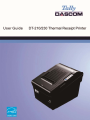
Tally Dascom DT-210/230
Important Safety Instructions (English) Read the following instructions thoroughly before starting up your printer. • Never carry out maintenance or repair work yourself. Always contact a qualified service technician. • Keep this user guide in a place which is easily accessible at all times. • Place the printer on a solid and even base so that it cannot fall. • Never place the printer in the vicinity of inflammable gas or explosive substances. • Ensure the printer is connected to a socket with the correct voltage. • Always disconnect the printer from the power before opening the device to perform maintenance work or remedy errors. • Do not expose the printer to high temperatures, direct sunlight or dust. • Keep all liquids away from the printer. • Protect the printer from shock, impact and vibration. • Make sure that both the printer and the computer are switched off before connecting the data cable. • The print head will become very hot during printing; avoid contact with the print head after printing has finished. • Do not perform any operation or action in any way other than those provided in this manual. When in doubt, contact your dealer or your customer support. I
Tally Dascom DT-210/230
Wichtige Sicherheitshinweise (German) Lesen Sie bitte diese Sicherheitshinweise durch, bevor Sie den Drucker in Betrieb nehmen.
Führen Sie Wartungsarbeiten und Reparaturen keinesfalls selbst aus, sondern verständigen Sie immer einen qualifizierten Servicetechniker.
Bewahren Sie diese Dokumentation an einem jederzeit zugänglichen Ort auf.
Den Drucker auf stabilem und ebenem Untergrund so aufstellen, dass er nicht zu Boden fallen kann.
Stellen Sie den Drucker keinesfalls in der Nähe von leicht entzündlichen Gasen oder explosiven Stoffen auf.
Den Drucker nur an eine Steckdose mit der richtigen Spannung anschließen.
Wenn Sie den Drucker vom Netz trennen wollen, den Drucker ausschalten und immer den Netzstecker an der Steckdose ziehen.
Den Drucker weder hohen Temperaturen noch direktem Sonnenlicht und Staub aussetzen.
Keine Flüssigkeiten mit dem Drucker in Berührung bringen.
Den Drucker keinen Erschütterungen, Stößen oder Vibrationen aussetzen.
Sicherstellen, dass der Drucker und der Computer ausgeschaltet sind, bevor das Datenkabel angeschlossen wird.
Der Druckkopf wird während des Druckens heiß. Vor dem Berühren deshalb einige Zeit abkühlen lassen.
Weichen Sie bei der Bedienung des Druckers nicht von den Anweisungen in der Dokumentation ab. Bei Unklarheiten wenden Sie sich bitte an Ihren Händler oder Ihren Kundendienst. II
Tally Dascom DT-210/230
Consignes importantes de sécurité (French) Lire attentivement les instructions suivantes avant de mettre l’imprimante en service.
Ne jamais effectuer soi‐même les travaux d’entretien et de réparations. Contacter toujours un dépanneur qualifié.
Placer l’imprimante sur un support stable de façon à ce qu’elle ne puisse pas tomber.
Ne jamais placer l’imprimante à proximité de sources de gaz aisément inflammables ou de substances explosives.
Ne connecter l’imprimante à une prise que lorsque la tension est correcte.
Pour déconnecter l’imprimante de l’alimentation principale, mettre l’imprimante hors tension et toujours débrancher le connecteur secteur de la prise murale.
Ne pas exposer l’imprimante à des températures élevées, à la lumière directe du soleil ou à la poussière.
Ne pas mettre l’imprimante en contact avec des liquides.
Ne pas exposer l’imprimante à des chocs, impacts ou vibrations.
S’assurer que l’imprimante et l’ordinateur sont hors tension avant de connecter le câble de données.
La tête d’impression est brûlante pendant l’impression. C’est pourquoi laissez‐la refroidir quelques instants avant d’y toucher.
N'exécutez aucune opération ni action d'une autre manière que celle indiquée dans ce manuel. En cas de doute, veuillez contacter votre distributeur ou service après‐vente. III
Tally Dascom DT-210/230
Indicazioni di sicurezza importanti (Italian) Prima di mettere in funzione la stampante, leggere attentamente le seguenti indicazioni.
Non eseguire mai da sé gli interventi di manutenzione e riparazione, ma rivolgersi sempre a un tecnico di assistenza qualificato.
Conservare le presenti istruzioni per l’uso in un luogo sempre accessibile.
Collocare la stampante su una superficie stabile, per evitare che cada a terra.
Non collocare la stampante in prossimità di gas facilmente infiammabili o di sostanze esplosive.
Collegare la stampante a una presa di corrente con tensione adeguata.
Per scollegare la stampante dalla rete di alimentazione, spegnere la stampante e disinserire sempre il connettore di rete dalla presa.
Non esporre la stampante ad elevate temperature né alla luce solare diretta e alla polvere.
Evitare il contatto della stampante con liquidi.
Non esporre la stampante a colpi, scosse o vibrazioni.
Verificare che la stampante e il computer siano spenti prima di collegare il cavo di trasmissione dati.
Durante la stampa, la testina si surriscal‐da notevolmente. Prima di toccarla, se necessario opportuno quindi lasciarla raffreddare qualche istante.
Non eseguire alcuna operazione o azione se non nella maniera descritta nel presente manuale. In caso di dubbio, contattare il rivenditore o dalla società incaricata dell’assistenza. IV
Tally Dascom DT-210/230
Instrucciones de seguridad importantes (Spanish) Lea las siguientes instrucciones con esmero antes de poner la impresora en servicio.
Nunca lleve a cabo trabajos de mantenimiento o reparación Ud. mismo, sino consulte a un técnico de servicio calificado.
Guarde las presentes instrucciones de servicio en un lugar de fácil acceso en cualquier momento.
Ponga la impresora sobre un base estable de manera que no pueda caer al suelo.
Nunca coloque la impresora en la vecindad de gases de fácil inflamabilidad o sunstancias explosivas.
Asegure conectar la impresora sólo a un enchufe con un voltaje correcto.
Cuando quiera desconectar la impresora de la red, apague la impresora y siempre tire la clavija de alimentación del enchufe.
No exponga la impresora a temperaturas altas, a la luz solar directa y al polvo.
No ponga la impresora en contacto con fluidos.
Nunca exponga la impresora a sacudidas, choques o vibraciones.
Asegúrese de que la impresora y el ordenador estén apagdos antes de conectar el cable de datos.
La cabeza de impresión se pone muy caliente durante la impresión. Por lo tanto, deje enfriarlo algún tiempo antes de tocarla.
No permita que se realice cualquier operación o acción de una forma diferente a lo que se señala en el manual. En caso de duda, póngase en contacto con su comerciante o con su servicio post‐venta. V
Tally Dascom DT-210/230
Правила по технике безопасности. (Russian) Прочитайте, пожалуйста, инструкцию по технике безопасности перед включением в работу принтера.
Не выполняйте технические работы и ремонт техники самостоятельно, но сообщайте о неисправностях квалифицированным сервисным техникам.
Данная инструкция должна быть всегда доступна каждому пользователю.
Установите принтер на ровном и стабильном месте так, чтобы он не смог упасть на пол.
Ни в коем случае не ставьте принтер вблизи легко воспламеняющихся газов и взрывчатых веществ.
Включайте принтер в розетку только с соответствующим напряжением.
Если Вы хотите отключить принтер от напряжения, сначала выключите принтер сам и затем выньте штекер из розетки.
Берегите принтер от нагревания, от попадания на него прямых солнечных лучей и пыли.
Не допускайте попадания жидкости на принтер.
Нельзя подвергать принтер тряске, ударам и вибрации.
Убедитесь, что принтер и компьютер выключены, только после этого соедините принтер с компьютером.
Печатающая головка нагревается во время работы принтера. Поэтому подождите какое‐то время, прежде чем дотронуться до нее.
Пользуйтесь принтером так, как это написано в документации. Если у Вас возникают неясности, обращайтесь с вопросами к Вашим продавцам или в сервисный центр. VI
Tally Dascom DT-210/230
Instruções Importantes sobre Segurança (Portuguese) Leia as instruções de segurança antes de usar a impressora.
Consulte sempre um técnico qualificado para executar uma reparação .
Coloque a impressora sobre uma base sólida e nivelada, para que ela não sofra quedas.
Jamais instale a impressora nas proximidades de lugares onde haja gás inflamável ou substâncias explosivas.
Assegure‐se de conectar a impressora à tomada elétrica com a voltagem apro‐priada.
Quando desligar a impressora da rede, desligue sempre a impressora e retire o cabo da tomada.
Não exponha a impressora a temperaturas altas ou luz solar direta.
Não aproxime substâncias líquidas da impressora.
Proteja a impressora de choques, impactos e vibrações.
Desligue a impressora e o computador antes de conectar o cabo da rede.
A cabeça da impressora pode ficar muito quente . Portanto, espere algum tempo antes de tocá‐la.
Não faça nenhuma operação ou ação além das recomendadas neste manual. Em caso de dúvida, contate seu revendedor ou companhia de serviço. VII
Tally Dascom DT-210/230
Önemli Güvenlik Talimatları (Turkish) Lütfen, yazıcıyı işletime geçirmeden önce bu güvenlik talimatlarını bütünüyle dikkatle okuyun.
Bakım ve tamir çalışmalarını kesinlikle ve hiçbir surette kendi başınıza yapmayın; her zaman kalifiye bir uzman servis‐teknisyenine haber verin.
Yazıcıyı, üzerinden yere düşmesi mümkün olmayacak sabit ve düz bir zemine yerleştirin.
Yazıcıyı kesinlikle ve hiçbir surette kolayca yanabilecek gaz veya patlayıcı maddeler içeren nesnelerin yakınına koymayın.
Yazıcı akım kablosunu sadece doğru gerilime sahip bir prize takın.
Yazıcıyı şebeke ağından ayırmak istediğinizde, yazıcıyı kapatın ve ağ‐fişini her zaman prizden çıkartın.
Yazıcıyı ne yüksek ısılı ne de doğrudan güneş ışığına ve toza mâruz kalan mekânlarda bulundurun.
Yazıcı hiçbir sıvı maddeyle temasta olmamalıdır.
Yazıcı hiçbir sarsıntıya, darbeye veya titreşime mâruz kalmamalıdır.
Veri kablosu bağlanmadan önce hem yazıcının hem de bilgisayarın kapalı olduklarından emin olmalısınız.
Yazıcının başı basma esnasında yüksek ısıya ulaşıyor. Bu yüzden lütfen dokunmadan önce kısa süre soğumasını bekleyin.
Yazıcının işletimi ve kullanımında bu dokümantasyondaki talimatların hiç dışına çıkmayın. Sorunlu görünen hususlarda lütfen imâlatçınıza veya müşteri hizmetleri servisinize başvurun. VIII
Tally Dascom DT-210/230
TRADEMARK ACKNOWLEDGEMENTS “IBM” is a trademark of International Business Machines Corporation. “EPSON” is a trademark of Epson America Incorporated. “DEC” is a trademark of Digital Equipment Corporation. “Centronics” is a trademark of Centronics Data Computer Corporation. “DOS” is a trademark of Microsoft Corporation. “SAP” is a trademark of SAP AG. “Windows”, “Windows 7”,”Windows 8”, “Windows 95”, “Windows 98“, “Windows NT”, “Windows 2000”, “Windows 2003/2008/2013 Server”, “Windows XP” and “Windows Vista” are trademarks of Microsoft Corporation. All other product names and company names appearing in this manual are the registered trademarks or trademarks of the individual companies. IX
Tally Dascom DT-210/230
TABLE OF CONTENTS 1 PRINTER INSTALLATION GUIDE..................................................................................................................... 1 Unpacking the printer .................................................................................................................................... 1 1.1 Placing the printer.......................................................................................................................................... 2 1.2 Printer components ....................................................................................................................................... 3 1.3 1.4 Connecting the interfaces .............................................................................................................................. 4 Connecting power .......................................................................................................................................... 6 1.5 1.6 Adjusting the near end sensor ....................................................................................................................... 7 Installing Roll Paper ........................................................................................................................................ 8 1.7 1.7.1 Installing 80mm Roll Paper ........................................................................................................................ 8 1.7.2 Installing 58mm Roll Paper ........................................................................................................................ 9 1.8 Installing the accessory and optional kits .................................................................................................... 10 1.9 Installing the printer driver .......................................................................................................................... 11 2 CONTROL PANEL OPERATION ....................................................................................................................... 18 3 SETTING DIP SWITCHES................................................................................................................................ 19 4 TROUBLESHOOTING..................................................................................................................................... 22 4.1 4.2 4.3 Processing LED and printing error ................................................................................................................ 22 Removing jammed paper ............................................................................................................................. 23 Cleaning thermal print head ........................................................................................................................ 24 5 SPECIFICATIONS ........................................................................................................................................... 25 Printer specification ..................................................................................................................................... 25 5.1 Interfaces ......................................................................................................................................................27 5.2 5.2.1 USB interface.............................................................................................................................................27 5.2.2 Cash Drawer interface ...............................................................................................................................27 5.2.3 Serial interface ......................................................................................................................................... 28 5.2.4 Parallel interface ...................................................................................................................................... 28 5.2.5 Ethernet interface .................................................................................................................................... 30 5.2.6 Wi‐Fi interface ......................................................................................................................................... 30 5.3 Power adapter.............................................................................................................................................. 30 Paper specification ....................................................................................................................................... 31 5.4 6 CHARACTER CODE PAGES............................................................................................................................. 33 7 PRINTING CONTROL COMMAND SETS.......................................................................................................... 48 FCC STATEMENT.............................................................................................................................................. 52 DASCOM REPRESENTATIVES............................................................................................................................ 53 Tally Dascom DT-210/230
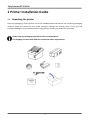
1 Printer Installation Guide 1.1 Unpacking the printer Open the packaging, lift the printer out of the cardboard box and remove the remaining packaging material. Check the printer for any visible transport damage and missing items. If you find any transport damage or any accessories are missing, please contact your dealer for assistance. Please keep the packaging material for future transportation. The shipping list varies with different customized order requirements. 1
Tally Dascom DT-210/230
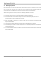
1.2 Placing the printer Place the printer on a solid, flat, stable surface; ensure that the printer is positioned in such a way that it cannot move, and that there is easy access to the control panel and roll paper holder. Also ensure that there is enough space for sufficient ventilation and for the printed output. When selecting the printer location, observe the following additional instructions: Never place the printer near to any flammable gas or explosive substances.
Do not expose the printer to direct sunlight. If you cannot avoid placing the printer near a window, protect it from the sunlight with a curtain.
When connecting a computer to the printer, make sure the maximum recommended cable length is not exceeded.
Ensure sufficient distance between the printer and any heating devices or radiators.
Avoid exposing the printer to extreme temperature or air humidity fluctuations. Avoid exposure to dusty environments.
It is recommended the printer is installed in a position which reduces noise exposure to the work place during printing. 2
Tally Dascom DT-210/230
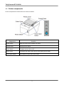
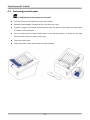
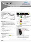
1.3 Printer components Printer components and functions are shown as below: Component Function Printer Cover Open the cover when loading roll paper. Control Panel Shows printer status. Power Switch To power printer ON or OFF. Cutter Cover To protect the auto‐cutter and to clear paper jam at cutter. Cover Open Button Press down to open the Printer Cover 3
Tally Dascom DT-210/230
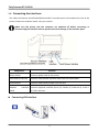
1.4 Connecting the interfaces The USB, Cash Drawer, Serial/Parallel/Ethernet/Wi‐Fi interface ports are located at the rear of the printer. Choose the interface which suits your system. Make sure the printer and the computer are switched off before connecting or disconnecting the interface cable to prevent electrical damage to the interface ports. Function Component Power Socket Connects power cord to the printer. Cash Drawer Interface Connects Cash Drawer interface cable from the cash drawer. USB Interface Connects USB interface cable from the host. Modular Board Interface Connects optional interface (Serial I/F, Parallel I/F, Ethernet I/F or Wi‐Fi I/F) from the host.
Connecting USB interface 4
Tally Dascom DT-210/230
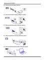
Connecting Cash Drawer interface
Connecting Parallel interface (Modular, option)
Connecting Serial interface (Modular, option)
Connecting Ethernet interface (Modular, option)
Connecting WLan interface (Wi‐Fi, Modular, option) 5
Tally Dascom DT-210/230
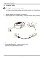
1.5 Connecting power Checking the voltage of the power adapter Before you connect the power adapter to the power socket check if the voltage is correct. If you connect the power adapter to power with incorrect voltage this may result in electrical damage to adapter and printer. 1. Make sure the printer and the computer are powered off ①. 2. Connect the power cord to the power adapter ②, and connect the power adapter to the power supply interface at the rear of the printer ③. Ensure the power cord is securely connected. Connect the power cord plug to a mains socket on the wall ④.
Power on and power off 1. Press the power switch to the “I” position to turn on the printer. Upon power‐on, the Power LED indicator light up. 2. Press the power switch to the “O” position to turn off the printer. 6
Tally Dascom DT-210/230
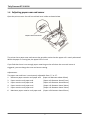
1.6 Adjusting paper near end sensor Open the printer cover. You will see a black lever inside as shown below. The printer has a paper near‐end sensor that provides notice that the paper roll is nearly exhausted. When the paper is running low, the paper LED is lit red. If you find that there is not enough paper remaining on the roll when the near‐end sensor is triggered, you can change the near‐end sensor setting. Adjustments: The paper near end lever is continuously adjustable from “1” to “6”. 1. Minimum paper remains until paper end. (Paper roll diameter about 26mm) 2. Paper remains until paper end. (Paper roll diameter about 27mm) 3. Paper remains until paper end. (Paper roll diameter about 28mm) 4. Paper remains until paper end. (Paper roll diameter about 30mm) 5. Paper remains until paper end. (Paper roll diameter about 32mm) 6. Maximum paper remains until paper end. (Paper roll diameter about 33mm) 7
Tally Dascom DT-210/230
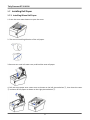
1.7 Installing Roll Paper 1.7.1 Installing 80mm Roll Paper 1. Press the cover open button to open the cover. 2. The correct installing direction of the roll paper. 3. Remove any used roll paper core, and load the new roll paper. 4. Pull out some paper over cutter cover as shown on the left picture below ①, then close the cover ② and tear off the paper as shown on the right picture below ③. 8
Tally Dascom DT-210/230
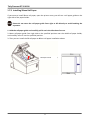
1.7.2 Installing 58mm Roll Paper If you want to install 58mm roll paper, open the printer cover, you will see a roll paper guide on the right side of the paper holder. Please do not move the roll paper guide from right to left directly to avoid breaking the separator. 1. Hold the roll paper guide and carefully pull it out in the direction of arrow. 2. Move roll paper guide from right side to the specified position near the middle of paper holder, and carefully insert it into the specified position. 3. Then you can install the 58 roll paper as 80mm roll paper installation above. Roll Paper Guide
9
Tally Dascom DT-210/230
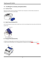
1.8 Installing the accessory and optional kits
Interface Cover Adjust the relative positions between interface cover and printer as shown below, and push the interface cover as arrow shows below.
Splash Cover (Optional Kit) Slip the fixed hooks on both sides of splash cover into the mounting hole on the printer, and close the splash cover.
Hanging Plate (Optional Kit) 1. Mount the hanging plate on the lower housing of the printer with screws ①; 2. Align the positioning holes of the hanging plate and plug into the fixed screws on the wall ②. 10
Tally Dascom DT-210/230
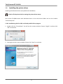
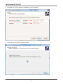
1.9 Installing the printer driver Installing the Windows Driver (Compatible with Windows) Switch off the printer before running the printer driver setup. Your printer CD‐ROM comes with Windows drivers. Go to the Drivers folder and run the installer “DriverSetup.exe”. 1.10.1 Installation guide for USB, serial and parallel driver program 1. Double click the “DriverSetup”. You will see the screen as below. Choose “English” and then click “OK” to continue. 2. You might see the screen as below. Please click “Next” to continue. 11
Tally Dascom DT-210/230
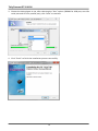
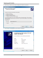
3. Choose the desired port to use, after selecting the “Port” option (USB001 for USB port, com1 for serial port and LPT1 for parallel port), click “Next” to continue. 4. Click “Finish” to finish the installation process successfully. 12
Tally Dascom DT-210/230
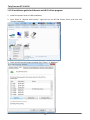
1.10.2 Installation guide for Ethernet and Wi‐Fi driver program 1. Install the printer driver as USB installation. 2. Click “Start”→ “Devices and Printers”, right click on the DT‐230 Printer Driver, and then click “Printer Properties”. 3. Then you will see the screen as below. Click “Ports” → “Add Port”. 13
Tally Dascom DT-210/230
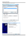
4. Select “Standard TCP/IP Port”, and click “New Port”. 5. You will see the screen as below, click “Next” to continue. 14
Tally Dascom DT-210/230
6. Complete the “Printer Name or IP Address” and “Port Name”. 7. Click “Next” to access the screen as below. 15
Tally Dascom DT-210/230
8. And then you will see the screen as below, click “Next” to continue. 9. Click “Finish” to complete the printer driver installation. 16
Tally Dascom DT-210/230
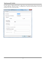
10. Click “Start”→ “Devices and Printers”, right click on the DT‐230 Printer Driver, and then click “Printer Properties”. Then click “Ports” → “Configure Port”, finish the setup parameter in the screen as below. Click “OK” to finish the setup. 17
Tally Dascom DT-210/230
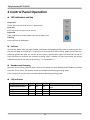
2 Control Panel Operation
LED indicators and key Power LED Power LED turns on while printer is powered on. Error LED Error LED turns on means error occurs. Paper LED Paper LED turns on means paper near end or paper end. Feed key Press Feed key to feed paper.
Self‐test Turn off the power after roll paper loaded, hold down the Feed key while printer is powering on, then the self‐test page is printed out. "If you want to continue SELF‐TEST printing, please press Feed key." would be printed out after the current printer status is printed, also Paper LED would be turned on; Press Feed key to continue the character printing. After a number of lines are printed, the printer indicates the end of the self‐test by printing "*** completed ***".
Hexadecimal Dumping Open the Printer Cover, load roll paper and turn the power on while holding down Feed key, and then close the Printer Cover, the printer would run Hexadecimal Dumping printing mode. Press Feed key for three times to exit Hexadecimal Dumping printing mode.
LED indicators Description Printer Cover is open Roll paper is sufficient Roll paper end Roll paper near end POWER ERROR PAPER BEEPER Short beep for twice and long beep for On On On once On Off Off No beep On On On Short beep for three times On Off On No beep 18
Tally Dascom DT-210/230
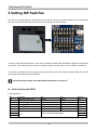
3 Setting DIP Switches You will see a metal plate on the bottom of the printer. Remove the metal plate with a screwdriver. You will find two DIP switches on the main control board as shown below. Metal Plate DIP Switch 1 & Switch 2 There are two DIP switch banks on the main controller board (SW1 and SW2), eight DIP switches for each bank. These DIP switches can be set on/off, using the tip of a tool, such as a small screwdriver. The printer parameter such as printer density, baud rate, and auto‐cutter enable/disable etc. can be set via these two DIP switches as follows. New DIP switch settings are enabled after the printer is turned on!
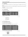
Serial Interface (RS‐232C) • DIP Switches 1 SW 1‐1 1‐2 1‐3 1‐4 1‐5 1‐6 1‐7 1‐8 Function Auto Line Feed at CR Handshaking Data Length Parity Check Parity Selection Baud Rate Selection (bps) ON Enable XON/XOFF 7bits Yes EVEN OFF Disable DTR/DSR 8bits No ODD Refer to the following table 1 19
Default OFF OFF OFF OFF OFF OFF ON OFF Tally Dascom DT-210/230
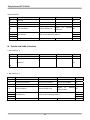
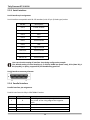
•DIP Switches 2 SW 2‐1 2‐2 2‐3 Function Reserved Internal bell control Auto Cutter ON ‐ Internal bell disable
Disable OFF ‐ Internal bell enable Enable 2‐4 BUSY Condition Receive Buffer Full Offline or Buffer Full 2‐5 2‐6 2‐7 2‐8 Print Density Refer to the following table 2 Near‐End Sensor Status Disable Default OFF OFF OFF Receive OFF Enable OFF OFF OFF OFF
Parallel and USB2.0 Interface • DIP Switches 1 SW 1‐1 1‐2 Function Auto Line Feed at CR ON Enable OFF Disable Default OFF ‐ OFF ‐ ~ Reserved 1‐8 • DIP Switches 2 SW 2‐1 2‐2 2‐3 Function Reserved Internal bell control Auto Cutter ON ‐ Internal bell disable Disable OFF ‐ Internal bell enable Enable 2‐4 BUSY Condition Receive Buffer Full Offline or Receive OFF Buffer Enable 2‐5 2‐6 2‐7 2‐8 Print Density Refer to the following Table 2 Near‐End Sensor Status Disable Enable 20
Default OFF OFF OFF OFF OFF OFF OFF Tally Dascom DT-210/230
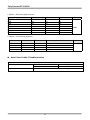
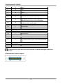
• Table 1 – Baud rate (bps) Selection Transmission Speed 2400 4800 9600 19200 38400 57600 115200 1‐6 ON ON OFF OFF OFF OFF ON 1‐7 OFF OFF ON OFF ON OFF ON 1‐8 OFF ON OFF OFF ON ON ON Default 19200 • Table 2 – Print Density Selection 2‐5 2‐6 2‐7 Print Density (Mono color) ON OFF ON OFF ON OFF OFF ON Reserved Reserved Reserved Reserved 1(Light) 2 3 4(Dark) Default 2
Auto Cutter Enable / Disable selection Dip Switch Set 2 SW 2‐3 Application ON Auto Cutter Disabled OFF Auto Cutter Enabled Ignores Auto Cutter error for continuous printing. 21
Tally Dascom DT-210/230
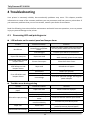
4 Troubleshooting Your printer is extremely reliable, but occasionally problems may occur. This chapter provides information on some of the common problems you may encounter and how you may solve them. If you encounter problems that you can not resolve, contact your dealer for assistance. Read the following instructions before maintenance and avoid incorrect operation, so as to prevent injury to you and damage to the printer. 4.1 Processing LED and printing error
LED indicator on the control panel and beeper alarm Trouble No LEDs on Potential Problem Solution Incorrect power supply cable Check the power supply cable connections connections and power and the power outlet and correct them. outlet PCB damaged Contact your dealer for assistance. Paper LED always on Paper near end The roll paper is near end, the printer can work normally, procure new paper. Error LED always on and beeper alarms Printer Cover open Close the Printer Cover. Power, Paper and Error LEDs always on and beeper alarms Paper end Reload the roll paper. Thermal Print Head overheated Overvoltage Turn the printer off and wait some minutes before you resume. Print with specified voltage. Low‐voltage Print with specified voltage, use original power adapter. Error LED blinks and beeper alarms
Troubles occur during printing Trouble Coloured stripe in the paper Potential Problem Solution Paper near end Install a new roll of paper. Incorrect roll paper Poor paper quality Dirty thermal head or print rooler Install the paper roll correctly. Use recommended thermal roll paper. Clean the thermal head or print rooler. Low Print density Increase the print density level. Paper Jam Paper stuck Vertical dot line missing Dirty thermal head or print Thermal head damaged Open the printer cover, check the paper path and remove jammed paper. Clean the thermal head or print rooler. Contact your dealer for assistance. Blurred or spot printing 22
Tally Dascom DT-210/230
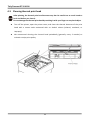
4.2 Removing jammed paper Printhead may be hot, please do not touch! Turn the printer off and press the cover open button.
Remove jammed paper, reinstall the roll, and close the cover.
If paper is caught in the cutter and you cannot open the printer cover, open the cutter cover as shown on the left below.
Turn the knob until the cutter blade returns to the normal position, as shown on the right picture below. There is a label to assist you.
Close the cutter cover.
Open the printer cover and remove the jammed paper. 23
Tally Dascom DT-210/230
4.3 Cleaning thermal print head After printing, the thermal print head becomes very hot. Be careful not to touch it and to let it cool before you clean it. Do not damage the thermal print head by touching it with your fingers or any hard object.
Turn off the printer, open the printer cover, and clean the thermal elements of the print head with a cotton swab moistened with an alcohol solvent (ethanol, methanol, or isopropyl).
We recommend cleaning the thermal head periodically (generally every 3 months) to maintain receipt print quality. 24
Tally Dascom DT-210/230
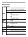
5 Specifications 5.1 Printer specification Print method Resolution Print speed Print width Interface Print Parameter Print density Power consumption Memory Receive buffer Fonts RAM Flash Characters per line User‐defined Code page Chinese Character Barcodes 1D 2D Direct thermal line printing 203DPI, 8dots/mm DT‐230: 260mm/s Default; 240‐270mm/s adjustable via DIP. DT‐210: 220mm/s Default; 210‐230mm/s adjustable via DIP. 72mm (576dots) USB (On‐board) + Cash Drawer (On‐board) + one optional interface (daughter board): Serial, Parallel, Ethernet, Wi‐Fi or fiscal interface. The density can be adjusted to different levels: DT‐210: Level 1 Density light: Speed 230 m/s Level 2 Density middle: Speed 220 m/s Level 3 Density middle: Speed 210 m/s Level 4 Density dark: Speed 200 m/s DT‐230: Level 1 Density light: Speed 270 m/s Level 2 Density middle: Speed 260 m/s Level 3 Density middle: Speed 250 m/s Level 4 Density dark: Speed 240 m/s 51.6W(Normal) 7W(Standby) 1Mbytes 4Mbytes 48Kbytes Font A, Special Font A: 48 cpl Font B, Special Font B: 64 cpl Supported 12 code pages (PC437, PC850, PC852, PC858, PC860, PC863, PC865, PC866, KU42, TIS11, TIS18, PC720) GB18030 24×24 UPC‐A, UPC‐E, EAN8, EAN13, CODE39, ITF, CODEBAR, CODE128, CODE32 PDR417, QR code Supports several bitmap densities and download image printing. (Maximum size of each bitmap is 64kB. The total size of memory is 256K.) Graphics Detect Function Sensors Paper End, Paper Near End, Paper Jam and Cover Open sensors. Power Supply Input Output External power adapter AC 100V‐240V 50‐60Hz DC 24V±5%, 2.15A, A‐1009‐3P interface 25
Tally Dascom DT-210/230
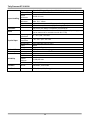
Paper type Paper width Paper thickness Paper Handling Paper roll diameter Paper load Paper cut Emulation Noise Physical Spec. Optional Kits Accessory Reliability Operating condition Storage condition Dimensions Color Weight Head lifetime MTBF Cutter lifetime MCBF Standard Thermal Paper (see P31‐ 5.4 paper specification) 79.5±0.5mm/57.5±0.5mm 0.056~0.1mm Max. OD ∮83mm Min. ID ∮13mm Upward cover open and Easy paper loading Manual tear; Auto‐cutter (hay cutter type) and partial cut. ESC/POS (TM‐T88IV) Compatible command set The noise level will be less than 50 dBA at 260mm/s printing speed (to be measured in accordance with ISO 7779) 5~45℃/10~95%RH ‐10~50℃/10~95%RH 147×198×146 (W×L×H mm) Black Approx. 1.8kg Splash cover and Hanging plate Interface cover 150km 360, 000 hours 2,000,000 cuts 52,000,000 lines Software Driver Windows, 32 & 64 Bit Certification CCC, CE, UL, FCC, Energy Star 26
Tally Dascom DT-210/230
5.2 Interfaces Power Supply interface, USB interface and cash drawer interface are standard interfaces for the printer. Serial interface, Parallel interface, Ethernet interface and Wi‐Fi interface are optional interfaces for the printer. The interface pin assignment is listed below. 5.2.1 USB interface USB interface pin assignment PIN No. Description 1 VBUS 2 D‐
3 D+
4 GND USB interface connector diagram Classic wire color
Red
White
Green
Black
5.2.2 Cash Drawer interface Cash Drawer interface pin assignment Cash drawer interface supports DC24V, 1A, RJ‐11 6P type socket. Pin. No. Description Direction Frame Ground ‐ 1 Drawer kick‐out drive signal 1 Output 2 Drawer open/close signal Input 3 +24V ‐ 4 Drawer kick‐out drive signal 2 Output 5 GND ‐ 6 Cash Drawer interface connector diagram 27
Tally Dascom DT-210/230
5.2.3 Serial interface Serial interface pin assignment Serial interface compatible with RS‐232 standard, with 25 pin (D hole type) socket. PIN No. Description PIN 1 Frame Ground PIN 2 TXD PIN 3 RXD PIN 4 RTS PIN 5 Unconnected PIN 6 DSR PIN 7 Signal Ground PIN 8~19 Unconnected PIN 20 DTR PIN 21~25 Unconnected User can view the setting of interface via printing configuration sample. The default setting of serial interface is as follow, 38400 bps (baud rates), 8 bit (data bit), 1 bit (stop bit), no parity, support RTS/CTS handshaking protocol. Serial interface connector diagram 5.2.4 Parallel interface Parallel interface pin assignment Parallel interface with 36 pin CENTRONICS socket. Pin No. Signal From Description Strobe Signal; Data latch pulse, latch the data to 1 H the printer at the rising edge of the negative pulse. 2 H Data 0 (The lowest bit) 3 H Data 1 4 H Data 2 28
Tally Dascom DT-210/230
5 6 7 8 9 H H H H H 10 P 11 P 12 P Data 3 Data 4 Data 5 Data 6 Data 7 (The highest bit) ACK Signal; Printer response signal, indicates that the printer has received a Data byte. Busy Signal; The printer is busy; High level indicates that the printer can’t receive data. PE Signal; Paper end signal; High level indicates that the printer is out of paper. Unconnected Unconnected Unconnected - - - Logic Ground Frame Ground, separated from logic ground. Unconnected - Logic Ground Unconnected - Printer error signal. Low level indicates that a 32 P error occurs in the printer. It will come with paper end. 33 Logic Ground 34~35 Unconnected - 36 Unconnected H indicates that signal comes from Host computer; P indicates that signal comes from Printer. 13 14 15 16 17 18 19~30 31 Parallel interface connector diagram 29
Tally Dascom DT-210/230
5.2.5 Ethernet interface Ethernet interface pin assignment Pin. No. Name Description 1 TX+ TX‐ RX+ n/c n/c RX‐ n/c n/c 2 3 4 5 6 7 8 Tranceive Data+ Tranceive Data‐ Receive Data+ Not connected Not connected Receive Data‐ Not connected Not connected Ethernet interface connector diagram 5.2.6 Wi‐Fi interface Wi‐Fi interface supports 2.4 GHz, IEEE Std. 802.11b standard. 5.3 Power adapter Power Socket pin assignment Pin Number Signal Name 1 2 3 SHELL +24 V GND N.C F.G. Power Supply connector diagram Power Supply interface type Printer ‐ Unetop DC‐002 or similar products Computer ‐ Unetop DP‐002 or similar products 30
Tally Dascom DT-210/230
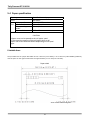
5.4 Paper specification Paper type Form Roll paper diameter Size Min. core diameter Take‐up roll paper width Paper width Specified thermal paper Roll paper 83 mm {3.27"} maximum 13mm 80 + 0.5/‐1.0 mm 79.5 ± 0.5 mm CAUTION • Paper must not be pasted to the roll paper spool. • The remaining amount of the roll paper when a roll paper near‐end is detected differs depending on the spool type. Printable Area The printable area of a paper with width of 79.5 ± 0.5 mm {3.13 ± 0.02"} is 72.2 ± 0.2 mm {2.84 ± 0.008"} (576 dots) and the space on the right and left sides are approximately 3.7 ± 2 mm {0.15 ± 0.079"}. Paper width
All the numeric values are typical.
31
Tally Dascom DT-210/230
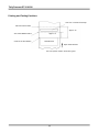
Printing and Cutting Positions Last Line of a Previous Receipt
Manual-Cutter Position
Approx. 29
Auto-Cutter Blade Position
Center of the Print Dotline
Approx. 15
Printable Area
Paper Feed Direction
Unit: mm (All the numeric values are typical.
32
Tally Dascom DT-210/230
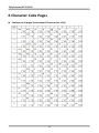
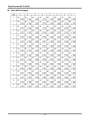
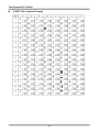
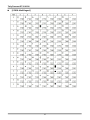
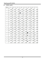
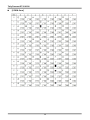
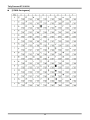
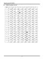
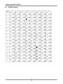
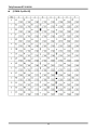
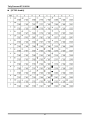
6 Character Code Pages
Common to all pages (International Character Set: USA) 33
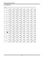
Tally Dascom DT-210/230
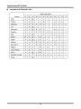
International Character Sets 34
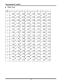
Tally Dascom DT-210/230
[User‐defined page] 35
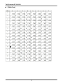
Tally Dascom DT-210/230
[PC437: USA, Standard Europe] 36
Tally Dascom DT-210/230
[PC850: Multilingual] 37
Tally Dascom DT-210/230
[PC852: Latin2] 38
Tally Dascom DT-210/230
[PC858: Euro] 39
Tally Dascom DT-210/230
[PC860: Portuguese] 40
Tally Dascom DT-210/230
[PC863: Canadian‐French] 41
Tally Dascom DT-210/230
[PC865: Nordic] 42
Tally Dascom DT-210/230
[PC866: Cyrillic #2] 43
Tally Dascom DT-210/230
[KU42: Thai] 44
Tally Dascom DT-210/230
[TIS11: Thai] 45
Tally Dascom DT-210/230
[TIS18: Thai] 46
Tally Dascom DT-210/230
[PC720: Arabic] 47
Tally Dascom DT-210/230
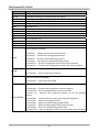
7 Printing Control Command Sets ∙ Be compatible with ESC/POS command set ∙ Support NV image and page mode printing List of Commands Command HT LF FF CR CAN DLE EOT DLE ENQ DLE DC4 ESC FF ESC SP ESC ! ESC $ ESC % ESC & ESC ESC − ESC 2 ESC 3 ESC = ESC ? ESC @ ESC D ESC E ESC G ESC J ESC L ESC M ESC R ESC S ESC T ESC V ESC W ESC \ Name Horizontal tab Print and line feed Print and return to standard mode (in page mode) Print and carriage return Cancel print data in page mode Transmit real‐time status Send real‐time request to printer Generate pulse in real‐time (fn = 1) Execute power‐off sequence (fn = 2) Clear buffer(s) (fn = 8) Print data in page mode Set right‐side character spacing Select print mode(s) Set absolute print position Select/cancel user‐defined character set Define user‐defined characters Select bit‐image mode Turn underline mode on/off Select default line spacing Set line spacing Select peripheral device Cancel user‐defined characters Initialize printer Set horizontal tab positions Turn emphasized mode on/off Turn double‐strike mode on/off Print and feed paper Select page mode Select character font Select an international character set Select standard mode Select print direction in page mode Turn 90 degrees clockwise rotation mode on/off Set print area in page mode Set relative print position 48
Tally Dascom DT-210/230
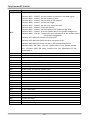
Command ESC a ESC c 3 ESC c 4 ESC c 5 ESC d ESC p ESC t ESC { FS g 1 FS g 2 GS ! GS $ GS ( A GS ( D Name Select justification Select paper sensor(s) to output paper‐end signals Select paper sensor(s) to stop printing Enable/disable panel buttons Print and feed n lines Generate pulse Select character code table Turn upside‐down print mode on/off Write to NV user memory Read from NV user memory Select character size Set absolute vertical print position in page mode Execute test print Enable/disable real‐time command Set user setup commands GS ( E <Function 1> Change into the user setting mode. <Function 2> End the user setting mode session. <Function 5> Set the customized setting values. <Function 6> Transmit the customized setting values. <Function 11> Set the configuration item for the serial interface. <Function 12> Transmit the configuration item for the serial interface. Request transmission of response or status GS ( H <Function 48> Set the process ID response. GS ( K Select print control method(s) <Function 50> Select the print speed. Set graphics data <Function 48> Transmit the NV graphics memory capacity. <Function 50> Print the graphics data in the print buffer. <Function 51> Transmit the remaining capacity of the NV graphics
memory. GS ( L / GS 8 L <Function 64> Transmit the key code list for defined NV graphics. <Function 65> Delete all NV graphics data. <Function 66> Delete the specified NV graphics data. <Function 67> Define the NV graphics data (raster format). <Function 69> Print the specified NV graphics data. <Function 112> Store the graphics data in the print buffer (raster format).
49
Tally Dascom DT-210/230
Command GS ( k Name Set up and print symbol
<Function 065> PDF417: Set the number of columns in the data region. <Function 066> PDF417: Set the number of rows. <Function 067> PDF417: Set the width of the module. <Function 068> PDF417: Set the row height. <Function 069> PDF417: Set the error correction level. <Function 070> PDF417: Select the options. <Function 080> PDF417: Store the data in the symbol storage area. <Function 081> PDF417: Print the symbol data in the symbol storage area. <Function 082> PDF417: Transmit the size information of the symbol data in
the symbol storage area. <Function 167> QR Code: Set the size of module. <Function 169> QR Code: Select the error correction level. <Function 180> QR Code: Store the data in the symbol storage area. <Function 181> QR Code: Print the symbol data in the symbol storage area. <Function 182> QR Code: Transmit the size information of the symbol data in GS GS / GS : GS B GS H GS I GS L GS P GS V GS W GS \ GS ^ GS a GS f GS g 0 GS g 2 GS h GS k GS r GS w FS p FS q GS v 0 Define downloaded bit image Print downloaded bit image Start/end macro definition Turn white/black reverse print mode on/off Select print position of HRI characters Transmit printer ID Set left margin Set horizontal and vertical motion units Select cut mode and cut paper Set print area width Set relative vertical print position in page mode Execute macro Enable/disable Automatic Status Back (ASB) Select font for HRI characters Initialize maintenance counter Transmit maintenance counter Set bar code height Print bar code Transmit status Set bar code width Print NV bit image Define NV bit image Print raster bit image 50
Tally Dascom DT-210/230
The commands listed below in the first column are defined as “obsolete commands” in the ESC/POS command system. This printer supports both upward‐compatible commands and obsolete commands. However, the upward‐compatible commands are recommended to use. Obsolete command ESC i Partial cut (one point left uncut) ESC m Partial cut (three points left uncut) ESC u Transmit peripheral device status ESC v Transmit paper sensor status FS p Print NV bit image FS q Define NV bit image GS v 0 Print raster bit image Upward‐compatible command GS V GS V GS r GS r GS ( L <Function 69> GS ( L <Function 67> GS ( L <Function 112 + 50> “Obsolete commands” are commands that are supported by legacy models; however it is recommended to replace them with upward‐compatible commands, because they will not be supported in the future products. 51
Tally Dascom DT-210/230
FCC STATEMENT 1. This device complies with Part 15 of the FCC Rules. Operation is subject to the following two conditions: a)This device may not cause harmful interference. b)This device must accept any interference received, including interference that may cause undesired operation. 2. Changes or modifications not expressly approved by the party responsible for compliance could void the user's authority to operate the equipment. This equipment has been tested and found to comply with the limits for a Class B digital device, pursuant to Part 15 of the FCC Rules. These limits are designed to provide reasonable protection against harmful interference in a residential installation. This equipment generates uses and can radiate radio frequency energy and, if not installed and used in accordance with the instructions, may cause harmful interference to radio communications. However, there is no guarantee that interference will not occur in a particular installation. If this equipment does cause harmful interference to radio or television reception, which can be determined by turning the equipment off and on, the user is encouraged to try to correct the interference by one or more of the following measures: Re‐orientate or relocate the receiving antenna. Increase the separation between the equipment and receiver. Connect the equipment into an outlet on a circuit different from that to which the receiver is connected. Consult the dealer or an experienced radio/TV technician for help. 52
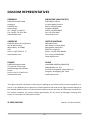
DASCOM REPRESENTATIVES GERMANY SINGAPORE (ASIA PACIFIC) DASCOM Europe GmbH Heuweg 3 D‐89079 Ulm Deutschland Tel.: +49 (0) 731 2075 0 Fax: +49 (0) 731 2075 100 www.dascom.com DASCOM AP Pte Ltd 21 Bukit Batok Crescent #29‐81, WCEGA Tower Singapore 658065 Phone: +65 6760 8833 Fax: +65 6760 1066 www.dascom.com AMERICAS UNITED KINGDOM DASCOM Americas Corporation 421 W. Main Street, Waynesboro, VA 22980 USA Phone:+1 (877) 434 13 77 www.dascom.com DASCOM GB Ltd Hart House, Priestley Road Basingstoke, Hampshire RG24 9PU, England Phone: +44 (0) 1256 481481 Fax: +44 (0) 1256 481400 www.dascom.com FRANCE CHINA DASCOM Europe GmbH 117 Avenue Victor Hugo 92100 Boulogne‐Billancourt France Phone: +33 (1) 73 02 51 98 www.dascom.com JIANGMEN DASCOM COMPUTER PERIPHERALS CO., LTD No. 399, Jinxing Road, Jianghai District, Jiangmen, Guangdong P.R. China www.dascom.com “All rights reserved. Translations, reprinting or copying by any means of this manual complete or in part or in any different form requires our explicit approval. We reserve the right to make changes to this manual without notice. All care has been taken to ensure accuracy of information contained in this manual. However, we cannot accept responsibility for any errors or damages resulting from errors or inaccuracies of information herein.” © 2013 DASCOM Part No.: 21.511.901.0021 53