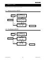
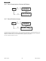
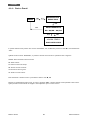
1
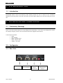
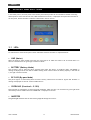
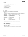
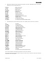
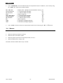
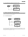
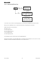
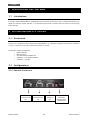
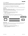
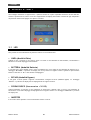
REMOTE PANEL
PANNELLO REMOTO
User’s manual
Manuale utente
Index/Indice
User’s Manual - English ........................................................................ 1
Safety Warnings ................................................................................. 1
1 SYSTEM DESCRIPTION ...................................................................... 2
1.1
Introduction ........................................................................... 2
2 INSTALLATION AND COMMISIONING ..................................................... 2
2.1
2.2
Preliminary Warnings ................................................................. 2
Configurator ........................................................................... 2
3 DISPLAY AND BUTTONS .................................................................... 4
3.1
3.2
3.3
3.4
LEDs.....................................................................................
Buttons .................................................................................
LCD Display ............................................................................
Buzzer ..................................................................................
4
5
6
8
4 MENU USAGE ................................................................................ 9
4.1
4.2
4.3
4.4
4.5
4.6
Buzzer Switch ON/OFF ............................................................... 9
Battery Test ON/OFF ................................................................. 9
Cancel Battery Test ................................................................. 10
Shutdown UPS ........................................................................ 10
Control UPS serial number and production date ................................ 11
Remote Comunication Panel Status Monitoring .................................. 11
5 PC COMMUNICATION ...................................................................... 15
6 TECHNICAL SPECIFICATIONS ............................................................. 15
Manuale Utente – Italiano .................................................................... 17
Avvisi di Sicurezza ............................................................................ 17
1 DESCRIZIONE DEL SISTEMA ............................................................... 18
1.1
Introduzione .......................................................................... 18
2 INSTALLAZIONE E UTILIZZO .............................................................. 18
2.1
2.2
Avvertenze ............................................................................ 18
Configurazione ....................................................................... 18
3 DISPLAY E TASTI ........................................................................... 20
3.1
3.2
3.3
3.4
LED ..................................................................................... 20
Tasti ................................................................................... 21
Display LCD ........................................................................... 22
Allarme Acustico ..................................................................... 24
4 MENU D’USO ................................................................................ 25
4.1
4.2
4.3
4.4
4.5
4.6
Allarme Acustico ON/OFF ........................................................... 25
Test Batteria ON/OFF ............................................................... 25
Annullare Test Batteria ............................................................. 26
Shutdown dell’UPS................................................................... 26
Controllo Numero Seriale e Data di Produzione dell’UPS ...................... 27
Stato del Pannello Remoto ......................................................... 27
5 COMMUNICAZIONE CON PC............................................................... 31
6 SPECIFICHE TECNICHE .................................................................... 31
ENGLISH
User’s Manual - English
Safety Warnings
Read this manual carefully and completely before installing and using the product.
The product must be used only by properly trained personnel. To ensure correct and safe
operations, it is necessary that operators and maintenance personnel observe the general
safety Standards as well as the specific instructions included in this manual.
Risk of electric shock: do not remove the cover. The product contains internal parts which are
at a high Voltage and are potentially dangerous, capable of causing injury or death by electric
shock.
There are no internal parts in the product which are user serviceable. Any repair or
maintenance work must be performed exclusively by qualified technical personnel authorized
by TECNOWARE. TECNOWARE declines any responsibility if this warning is disregarded.
The electric installation has to be done by qualified personnel. Follow all the Safety Standards
(CEI Standards in Italy or IEEE elsewhere).
Do not insert objects or pour liquids in the ventilation holes.
Install the product indoors, in a protected, clean and moisture-free environment.
Do not expose to the direct sun light.
Do not keep liquids, flammable gases or corrosive substances near the product.
Remote Panel
1
User’s manual
ENGLISH
1 SYSTEM DESCRIPTION
1.1 Introduction
TECNOWARE Remote Control and Monitoring Panel (RCMP) provides the user to monitor all the information
displayed on the front panel of the UPS, and control your UPS. RMCP enables you to save the history log of your
UPS.
2 INSTALLATION AND COMMISIONING
2.1 Preliminary Warnings
Check if the UPS has been subjected to any damage before unpacking it. If you notice any damage then contact
the transport company. Check if all the accessories have been supplied with the device.
A delivered pack includes:
•
•
•
•
•
RCMP
User’s Manual
RCMP - UPS Data Cable
RCMP - Adaptor Cable
Adaptor – UPS Cable
2.2 Configurator
2.2.1 Rear View
9 Pin Female
PC Connection
User’s manual
9 Pin Female
UPS Connection
9 Pin Male
Adaptor
Connection
2
Switch to chose
communication
distance
Remote Panel
ENGLISH
2.2.2 Installation
Please connect your RCMP to the mains with the power cable supplied with you RCMP. Turn the switch to ON
position. Your RCMP is ready to start. Even though you don’t connect your RCMP to the mains, it may
approximately 24 hours thanks to internal battery. Whenever you make the mains condition, the battery inside will
automatically start to charge.
2.2.3 Communication Interface Connection
If you use RCMP at a distance from 1.5m to 25m (serial cable 25m optional) from the UPS, do the following
instructions:
UPS Setting:
from the menu select “COMAND” press Enter button and with ▼ button check if is selected COMM=RS232. If not
press Enter button to change.
Check if the two dip switch on the UPS interface board are on RS232 position (both in down position).
Connect the communication cable to RS232 port.
RCMP Setting:
1
Position the two dip switch in Converter position (both in up position).
2
Connect the communication cable to UPS RS232 port.
3
Connect the power cable to RCMP.
4
Switch on RCMP.
If you use RCMP at a distance from 25m to 100m from the UPS, do the following instructions:
Use the two DB9 connectors supplied and wire the connection between a CAT.5 shielded cable.
UPS EVO DSP TT-TM
RS422 port
Male
DB9
Connector
Pannello Remoto
RS488 port
2
9
1
5
6
4
4
9
1
5
6
2
Female
DB9
Connector
UPS Setting:
from the menu select “COMAND” press Enter button and with ▼ button select RS232 and press enter to change
in RS485.
Check if the two dip switch on the UPS interface board are on RS232 position (both in down position).
Connect the communication cable to RS422 port.
RCMP Setting:
1
Position the two dip switch in UPS position (both in down position).
2
Connect the communication cable to Converter RS488 port.
3
Connect the power cable to RCMP.
4
Switch on RCMP.
Remote Panel
3
User’s manual
ENGLISH
3 DISPLAY AND BUTTONS
In the below picture, the front panel of the remote panel which provides all the information needed concerning
about operation of the UPS with the LCD, LEDs and buttons to the user, is displayed. Description and functions of
the LCD panel, buttons and other indicators is described in the ext section.
3.1 LEDs
Six indications are found on the panel. These indications and their functions are explained below:
• LINE (Mains)
When the mains is within normal limits then the green light is on. When the mains is out of normal limits or if
there is a blackout then the green light continues to blink.
• BATTERY (Battery Mode)
This red light is not on, when the UPS is operating from mains, but when it is on Battery mode, “MN ABNML” is
message is displayed on the LCD and an audible warning alarm is heard. When the battery capacity is less than 30
%, the light continues to blink.
• BY-PASS (By-pass Mode)
This yellow light is on continuously when the load is directly connected to the mains or by-pass and “BYPACT” is
message is displayed on the LCD “with an audible alarm”.
• OVERLOAD (Overload > % 100)
This indication is continuously on during overload conditions. When the UPS is on overload the green light blinks
continuously with an audible alarm and “OVERLOAD” is displayed on the LCD.
• INVERTER
This green light indicates that the load is being supplied through the inverter.
User’s manual
4
Remote Panel
ENGLISH
• FAULT
•
•
•
•
•
•
•
•
•
If the semi-conductor junction temperature exceeds the upper limit.
If the cooling temperature, exceeds the upper limit.
If the Battery temperature exceeds the upper limit.
If there is a Fan malfunction.
If the Battery fuse goes off.
If the battery test isn’t successful.
If there is an inverter failure.
If there is an Output error.
Or if there is any fault.
This light blinks and gives an audible alarm.
3.2 Buttons
There are 4 buttons on the RCMP. These buttons have the following functions:
•
“▼” Button
This button shows all the stored digital information by scanning it and provides to adjust some values to
negative. The digital information is in the following order:
•
•
•
•
•
•
•
•
•
•
LD1, LD2,LD3
Vsc1,Vsc2,Vsc3
Isc1,Isc2,Isc3
Fout
Vby1,Vby2,Vby3
Vin1,Vin2,Vin3
Iin1,Iin2,Iin3
Fin
Vbtp
Vbtn
: Output power - [ Output current/Nominal current
: r,s,t Phases Output Voltages
: r,s,t Phases Output Currents
: Output Frequency
: r,s,t Phases Bypass Voltages
: r,s,t Phases Input Voltages
: r,s,t Phases Input Currents
: Input Frequency
: Total Battery Voltage (positive)
: Total Battery Voltage (negative)
] (%)
(V)
(A)
(Hz)
(V)
(V)
(A)
(Hz)
(V)
(V)
• “▲” Button
This button has functions the same with
“▼“ button, but to the positive direction.
• “ESC” (Escape) Button
This button provides you to get out from the menu, and pass to the other menu table.
• “ENT” (Enter) Button
This button provides you to enter main menu on the screen, confirmation of the changes.
Remote Panel
5
User’s manual
ENGLISH
3.3 LCD Display
The LCD panel displays the UPS mode, status, active alarms, and messages related to the errors or failures
numerically. As shown in the diagram below, the messages that give information related to the UPS can be seen in
specific areas of the LCD panel. In this section these messages and their meanings are explained.
User’s manual
6
Remote Panel
ENGLISH
•
Abbreviations related to the UPS’s operation status appear in the space “OPERATION STATUS” as seen above.
Following is a list of the abbreviations used.
BTSTACT
S.D.ACT
BZ. ACT
BYPSWON
INV OFF
RCT ACT
RCT DIS
INV DIS
BYPMDIS
GREENMD
GENSET
OFFSWON
DCBUSCH
NO COMM 1
•
: Battery Test Active
: Shut Down Active
: Buzzer Active
: Bypass Switch On
: Inverter Off
: Rectifier Active
: Rectifier not Active
: Inverter not Active
: Bypass Mode not Active
: ECO Mode (Bypass Priority Mode)
: GENSET Active
: UPSOFF Switch On
: DC Capacitors Charging
: No Communication between RCMP and UPS
The abbreviations for relevant alarms seen above in the “ALARM” portion of the LCD are as follows 2:
OK
MN ABNL
BATT LOW
UPSFAULT
BYP V FA
BYP V HI
BYP V LO
BYP SYNC
BYP SEQ:
INV TEMP
OUT OVER
BYP ACT.
INV BLO.
SBUS V F
INP V HI
INP V LO
INP SYNC
INP SEQ.
RCT TEMP
RCT OVER
DCBUSVHI
DCBUSVLO
RCT BLO.
BT DISCH
DCBUSVFA
TEMP HI
BT TST F
OVERLOAD
WITH UPS 1
: No Alarm
: Abnormal Mains
: Low Battery Voltage
: Fault (see. FAULT LED)
: Bypass Voltage out of limits.
: High Bypass Voltage
: Low Bypass Voltage
: Bypass Synchronization
: Bypass Sequence
: Inverter Overheated
: Output Overloaded
: Bypass Active
: Inverter Blocked
: Output Voltage Out-of-Limits
: High Input Voltage
: Low Input Voltage
: Input Synchronization
: Input Sequence
: Rectifier Overheated
: Rectifier Overloaded
: High DC Bus Voltage
: Low DC Bus Voltage
: Rectifier Blocked
: Battery Discharging
: DC Bus Voltage Out-of-Limits
: High Ambient Temperature
: Battery Test Failure
: Overload
: No Communication between RCMP and UPS
Note 1: These messages are meaningful only when they are seen at the same time.
Note 2: In the event of more than one alarm occurring at the same time, the code for the alarm that occupies the
last position in the row will appear.
Remote Panel
7
User’s manual
ENGLISH
•
In the “PARAMETERS” section the abbreviations for the parameters that are looked for, can be seen by using
the “MODE” key. These can be listed as follows:
LD1, LD2, LD3
Vsc1,Vsc2,Vsc3
Isc1,Isc2,Isc3
Fout
Vby1,Vby2,Vby3
Vin1,Vin2,Vin3
Iin1,Iin2,Iin3
Fin
Vbtp
Vbtn
•
: Output power - [Output current/Nominal current]
: r,s,t Phases Output Voltages
: r,s,t Phases Output Currents
: Output Frequency
: r,s,t Phases Bypass Voltages
: r,s,t Phases Input Voltages
: r,s,t Phases Input Currents
: Input Frequency
: Total Battery Voltage (positive)
: Total Battery Voltage (negative)
(%)
(V)
(A)
(Hz)
(V)
(V)
(A)
(Hz)
(V)
(V)
In the “VALUE” section the values for the parameter chosen can be seen using the
“▲“ or “▼” buttons.
3.4 Buzzer
•
•
•
•
When the FAULT sign switches on and off.
When the UPS is in the battery mode.
When the system experiences an overload (overload, out over).
When the RCMP battery voltage is low.
The buzzer sounds an audible alarm every 2 seconds.
User’s manual
8
Remote Panel
ENGLISH
4 MENU USAGE
Push the “ENT” button to enter the main menu.
4.1 Buzzer Switch ON/OFF
ENT
*****MENU****
MENU
REMOTE CONTROL
ENT
Remote Control
Main Screen
Buzzer ON / OFF
ENT
ESC
TOGGLE BUZZER ?
NO / YES
YES
Buzzer on / off
4.2 Battery Test ON/OFF
ENT
*****MENU****
MENU
REMOTE CONTROL
ENT
▼x1
Batt. Test
Main Screen
ON / OFF
ENT
ESC
Str/Stp?
NO / YES
Remote Panel
9
YES
Battery Test
User’s manual
ENGLISH
4.3 Cancel Battery Test
ENT
*****MENU****
MENU
REMOTE CONTROL
ENT
Main Screen
▼x2
Cancel Batt. Test
ENT
ESC
Stop Batt Test ?
NO / YES
YES
Cancel Batt. Test
4.4 Shutdown UPS
ENT
*****MENU****
MENU
REMOTE CONTROL
ENT
Main Screen
▼x2
Shut Down UPS
ENT
ESC
Turn Off UPS?
NO / YES
YES
NO
Are You Sure?
NO / YES
User’s manual
10
YES
Shutdown UPS
Remote Panel
ENGLISH
4.5 Control UPS serial number and production date
ENT
▼
REMOTE CONTROL
MENU
UPS IDENTITY
ENT
ESC
Model:
PD XXXkVA
Version: 1.0
4.6 Remote Comunication Panel Status Monitoring
In this menu, some parameters like hour/ date, communication mode, software version, monitor internal battery
voltage, clear history log and LCD contrast may be adjusted.
4.6.1 Hour/Date Adjustment
MENU
ENT
▼x2
UPS IDENTITY
RCMP STATUS
ENT
RCMP Time / Date
ESC
hh/mm/ss dd / mm
ENT
CHANGE TIME ?
ESC
NO / YES
ENT
In this sub-menu, hour and date of RCMP Module may be adjusted. The values may be adjusted in up or down
directions with ▼, ▲ buttons. To enter the next parameter (ex. from hour to minute adjusting), push “ ENT “
button once and make adjust with ▼, ▲ buttons. After month parameter adjusting, push “ ENT “ button and exit
from hour/date menu. For canceling, push “ ESC “ button.
Remote Panel
11
User’s manual
ENGLISH
4.6.2 Monitoring Communication Mode and Software Version
ENT
▼x2
UPS IDENTITY
RCMP STATUS
MENU
ENT ▼
Comm. Via RS XXX
ESC
SW Version X.XX
4.6.3 Monitoring Internal Battery Status
ENT
▼x2
UPS IDENTITY
RCMP STATUS
MENU
ENT ▼ x 2
ESC
Inter. Batt.
XXX V
%XXX
RCMP has internal battery. In case of electricity cuts, internal battery provides 4 hours back up time to RCMP. If
the battery voltage is lower than 12V, “Ibatt Low” warning will be displayed on the main screen. If the voltage
decreases lower 10V, RCMP will shutdown automatically.
If the mains exist, batteries are charged.
User’s manual
12
Remote Panel
ENGLISH
4.6.4 Clear History Log
ENT
▼x2
UPS IDENTITY
RCMP STATUS
MENU
ENT ▼ x 3
ESC
ERASE EVENT
FILE
ENT
ESC
ARE YOU SURE ?
NO / YES
ENT
All the history log will be cleared. It takes about 30 seconds.
4.6.5 Contrast Adjustment
MENU
ENT
UPS IDENTITY
RCMP STATUS
▼x2
ENT ► x 4
ESC
CONTRAST
ENT
ESC
Change Contrast
XXX
ENT
In this menu, contrast of RCMP monitor may be adjusted. Values may be adjusted in up or down directions with
the ▲, ▼ buttons. Make confirmation by push “ENT” button. For cancelling, push “ESC” button.
Remote Panel
13
User’s manual
ENGLISH
4.6.6 Monitoring History Log
ENT
▼x3
MENU
RCMP STATUS
EVENT FILE
ENT
XXXXXXXXXXXXX
ESC
KK- SS/DD
ESC
GG/AA
ENT
ALARM STRING
XXXX XXXX XXXX
In this section, there are other events being displayed. To view them press the ▼ button and then press "ENT ".
When you enter “Event File” menu, it is shown the latest history. The parameters are as follows:
XXXXXX: Description of the saved history.
KK: Event save turn.
SS: Event happening time.
DD: Event happening minutes.
GG: Event happening day.
AA: Event happening month.
You may display previous or latest history events using ▲, ▼ buttons.
During the event display, if you push “ENT” button, it will show you some parameters at the event time. These
parameters are shown at attachment and important for your technical service.
User’s manual
14
Remote Panel
ENGLISH
4.6.7 Monitoring Momentary Alarms
ENT
EVENT FILE
▼x4
MENU
ALARMS
ENT
ALARM STRING
ESC
XXXX XXXX XXXX
ESC
ENT
ALARM STRING-ANN
TTTTTTTTTTTTTTT
Momentary alarms on UPS may be seen by this menu. In main menu, under “ALARM STRING” part, 3 lines with 4
characters are seen. In this menu, if you push “ENT” button, alarms related to this line may be seen. To enter
other alarms, “▼ “or “▲ ” buttons may be used.
5 PC COMMUNICATION
Please connect the data cable given with the software to 9 pin female PC socket of your RCMP and the other side
to your PC.
6 TECHNICAL SPECIFICATIONS
Mains input voltage range: 100-260 Vac – 50/60 Hz automatic
Internal battery back up time: about 24 hours
Working temperature: -5/+50°C
Remote Panel
15
User’s manual
ENGLISH
User’s manual
16
Remote Panel
ITALIANO
Manuale Utente – Italiano
Avvisi di Sicurezza
Leggere attentamente e completamente questo manuale prima di installare ed utilizzare il
prodotto.
Il prodotto deve essere utilizzato solo da personale opportunamente istruito. Per l’uso corretto
e in condizioni di sicurezza è necessario che gli operatori ed il personale di manutenzione si
attengano alle norme generali di sicurezza, in aggiunta alle norme specifiche contenute in
questo manuale.
Rischio di shock elettrico: non rimuovere il coperchio. Il prodotto presenta parti interne sotto
tensione che sono potenzialmente pericolose e possono provocare lesioni o morte per shock
elettrico.
Il prodotto non ha parti interne soggette a manutenzione da parte dell’utente. Interventi
tecnici di qualsiasi tipo devono essere compiuti solo da personale tecnico specializzato ed
autorizzato da TECNOWARE. In caso contrario TECNOWARE declina ogni sua responsabilità.
L'installazione elettrica, nonostante la sua semplicità, deve essere eseguita esclusivamente da
elettricisti qualificati. Seguire scrupolosamente tutte le norme locali e nazionali (in ITALIA le
norme CEI.
Non inserire oggetti o versare liquidi nei fori di ventilazione.
Installare il prodotto in ambiente chiuso, pulito e privo di umidità.
Non esporre il prodotto alla luce diretta del sole.
Non avvicinare liquidi, gas infiammabili o sostante corrosive.
Pannello Remoto
17
Manuale Utente
ITALIANO
1 DESCRIZIONE DEL SISTEMA
1.1 Introduzione
Il pannello remoto TECNOWARE per UPS EVO DSP TT-TM consente di monitorare tutte le informazioni presenti sul
display sul pannello frontale dell’UPS, e di controllare quest’ultimo. Consente inoltre di salvare lo storico degli
eventi dell’UPS.
2 INSTALLAZIONE E UTILIZZO
2.1 Avvertenze
Verificare se il prodotto ha subito danni prima di disimballarlo. Se è presente un qualsiasi tipo di danno contattare
il corriere. Verificare se tutti gli accessori sono presenti a corredo.
La dotazione completa comprende:
•
•
•
•
•
Pannello Remoto
Manuale Utente
Cavo dati Pannello Remoto-UPS
Adattatore - Cavo Pannello Remoto
Adattatore – Cavo UPS
2.2 Configurazione
2.2.1 Pannello Posteriore
Connettore
femmina PC 9
Pin
Manuale Utente
Connettore
femmina UPS p
Pin
Adattatore
machio 9
pin
18
Switch per la
scelta della
distanza della
comunicazione
Pannello Remoto
ITALIANO
2.2.2 Installazione
Collegare il pannello remoto all’alimentazione tramite il cavo a corredo. Porre l’interruttore sulla posizione ON. Il
pannello remote è pronto per l’utilizzo. Anche nel caso in cui non si colleghi il pannello remote all’alimentazione,
è possibile utilizzarlo comunque grazie alla batteria interna che garantisce un’autonomia di circa 24 ore. Ogni
volta che l’alimentazione viene ripristinata, la batteria interna comincia la fase di ricarica.
2.2.3 Connessione con l’Interfaccia di Comunicazione
Se si utilizza il pannello remoto ad una distanza da 1.5m a 25m (cavo seriale 25m opzionale) dall’UPS, fare
quanto segue:
Impostazione UPS:
dal menu selezionare “COMANDI” premendo il tasto Enter con la freccia giù verificare che sia impostato su
COMM=RS232. Eventualmente premere Enter per impostare.
Assicurarsi che i due dip switch sulla scheda interfacce dell’UPS siano in posizione RS232 (entrambi in basso).
Connettere il cavo di comunicazione alla porta denominata RS232.
Impostazione Pannello:
1
Posizionare i due dip switch in posizione Converter (tutti e due in alto).
2
Connettere il cavo di comunicazione alla porta denominata UPS RS232.
3
Connettere il cavo di alimentazione al pannello remoto.
4
Accendere il pannello remoto.
Se si utilizza il pannello remoto ad una distanza da 25m a 100m dall’UPS, fare quanto segue:
Utilizzare i due connettori DB9 in dotazione e cablare il collegamento tramite un cavo CAT.5 schermato.
Lato UPS EVO DSP TT-TM
porta RS422
Connettore
DB9
Maschio
Lato Pannello Remoto
porta RS488
2
9
1
5
6
4
4
9
1
5
6
2
Connettore
DB9
Femmina
Impostazione UPS:
dal menu selezionare “COMANDI” premendo il tasto Enter con la freccia giù selezionare RS232 e premere Enter per
cambiare in RS485.
Assicurarsi che i due dip switch sulla scheda interfacce dell’UPS siano in posizione RS232 (entrambi in basso).
Connettere il cavo di comunicazione alla porta denominata RS422.
Impostazione Pannello:
1
Posizionare i due dip switch in posizione UPS (tutti e due in basso).
2
Connettere il cavo di comunicazione alla porta denominata Converter RS488.
3
Connettere il cavo di alimentazione al pannello remoto.
4
Accendere il pannello remoto.
Pannello Remoto
19
Manuale Utente
ITALIANO
3 DISPLAY E TASTI
Nell’immagine sottostante è rappresentato, il pannello remoto con il quale è possibile monitorare lo stato dell’UPS
tramite la presenza di led, tasti e di ciò che è rappresentato sul display. Descrizione e funzioni di ogni componente
del pannello remoto sono spiegate nei capitoli successivi.
3.1 LED
Sono presenti 6 led di indicazione sul pannello remoto. Le loro funzioni sono:
• LINEA (Modalità Rete)
Quando la rete è presente il led verde è attivo. Se siamo in una situazione di sottotensione, sovratensione o
blackout il led verde lampeggia continuamente.
• BATTERIA (Modalità Batteria)
Il led rosso non è attivo quando l’Ups si trova in modalità rete, ma se siamo in una situazione di assenza rete, il
messaggio “MN ABNML” è presente sul display LCD ed è presente un segnale acustico. Quando la capacità delle
batterie è inferiore al 30 % il led continua a lampeggiare.
• BYPASS (Modalità Bypass)
Il led giallo è attivo quando l’ingresso è direttamente collegato all’uscita (modalità Bypass) e il messaggio
“BYPACT” è presente sul display LCD accompagnato da un segnale acustico.
• SOVRACCARICO (Sovraccarico > % 100)
Questa indicazione è presente in una condizione di sovraccarico. Quando l’UPS si trova in una situazione di
sovraccarico il led verde lampeggia accompagnato da un segnale acustico e il messaggio “OVERLOAD” è presente
sul display LCD.
• INVERTER
Il led verde è attivo quando il carico è alimentato tramite l’inverter.
Manuale Utente
20
Pannello Remoto
ITALIANO
• CONDIZIONE DI ERRORE
•
•
•
•
•
•
•
•
•
Se
Se
Se
Se
Se
Se
Se
Se
Se
la temperatura dei moduli di potenza supera i limiti consentiti.
la temperature di raffreddamento supera i limiti consentiti.
la temperature delle batterie supera i limiti consentiti.
è presente un malfunzionamento sulle ventole.
il fusibile batterie è interrotto.
il test batterie non è passato con successo.
è presente un problema sul circuito inverter.
è presente un problema sull’uscita.
sono presenti altri errori.
In queste condizioni di errore il led si “FAULT” lampeggia accompagnato da un segnale acustico.
3.2 Tasti
Sono presenti 4 tasti sul pannello remoto. I tasti hanno le seguenti funzioni:
•
Tasto “▼”
Questo tasto permette di mostrare tutte le informazioni memorizzate dalla scansione dell’UPS e consente di
adeguare alcuni valori. Le informazioni sono nel seguente ordine:
•
•
•
•
•
•
•
•
•
•
LD1, LD2,LD3
: Potenza d’uscita - [Corrente d’uscita/Corrente nominale] (%)
Vsc1,Vsc2,Vsc3
: r,s,t Tensione d’uscita sulle fasi
(V)
Isc1,Isc2,Isc3
: r,s,t Corrente d’uscita sulle fasi
(A)
Fout
: Frequenza d’uscita
(Hz)
Vby1,Vby2,Vby3 : r,s,t Tensione sulle fasi in modalità Bypass
(V)
Vin1,Vin2,Vin3
: r,s,t Tensione d’ingresso sulle fasi
(V)
Iin1,Iin2,Iin3
: r,s,t Corrente d’ingresso sulle fasi
(A)
Fin
: Frequenza d’ingreso
(Hz)
Vbtp
: Tensione totale di batterie (positivo)
(V)
Vbtn
: tensione totale di batterie (negativo)
(V)
• Tasto “▲”
Questo tasto ha la stessa funzione del tasto
“▼“, ma nel senso opposto.
• Tasto “ESC” (Uscita)
Questo tasto consente l’uscita da un menu e l’accesso ad un’altro menu.
• Tasto “ENT” (Conferma)
Questo tasto consente l’accesso ad un menu e la conferma di un’impostazione.
Pannello Remoto
21
Manuale Utente
ITALIANO
3.3 Display LCD
Il display LCD mostra il tipo di modalità, lo stato, gli allarmi attivi e i messaggi relativi ad errori e numeri di
fallimenti dell’UPS. Come è rappresentato nella figura sotto, il messaggio che da la risposta relativa all’UPS è
rappresentato in una’area specifica del display LCD. In questa sezione sono spiegati i messaggi e i loro significati.
Manuale Utente
22
Pannello Remoto
ITALIANO
•
Le abbreviazioni riguardanti lo stato dell’UPS appaiono nello spazio “OPERATION STATUS” sul display
LCDcome si vede sotto. Di seguito la lista delle abbreviazioni utilizzate.
BTSTACT
S.D.ACT
BZ. ACT
BYPSWON
INV OFF
RCT ACT
RCT DIS
INV DIS
BYPMDIS
GREENMD
GENSET
OFFSWON
DCBUSCH
NO COMM 1
•
: Test Batterie Attivo
: Shut Down Attivo
: Buzzer Attivo
: Switch di Bypass attivo
: Inverter Disattivato
: Raddrizzatore Attivo
: Raddrizzatore non Attivo
: Inverter non Attivo
: Modalità Bypass non Attivo
: ECO Mode (Bypass Priority Mode)
: GENSET Attivo
: Switch UPSOFF Attivo
: Carica DC Condensatori
: Non è presente la comunicazione tra Pannello Remoto e UPS
Le abbreviazioni per gli allarmi rilevanti riportati nello spazio “ALARM” sul display LCD sono i seguenti:
OK
MN ABNL
BATT LOW
UPSFAULT
BYP V FA
BYP V HI
BYP V LO
BYP SYNC
BYP SEQ:
INV TEMP
OUT OVER
BYP ACT.
INV BLO.
SBUS V F
INP V HI
INP V LO
INP SYNC
INP SEQ.
RCT TEMP
RCT OVER
DCBUSVHI
DCBUSVLO
RCT BLO.
BT DISCH
DCBUSVFA
TEMP HI
BT TST F
OVERLOAD
WITH UPS 1
: Nessun Allarme
: Alimentazione non normale
: Tensione Batterie Bassa
: Errore (vedi LED di FAULT)
: Tensione di Bypass Fuori dai Limiti.
: Tensione di Bypass Alta
: Tensione di Bypass Bassa
: Sincronizzazione Bypass
: Sequenza Bypass
: Inverter Surriscaldato
: Sovraccarico in Uscita
: Bypass Attivo
: Inverter Bloccato
: Tensione di Uscita Fuori dai Limiti
: Tensione di Ingresso Alta
: Tensione di Ingresso Bassa
: Sincronizzazione Ingresso
: Sequenza ingresso
: Raddrizzatore Surriscaldato
: Sovraccarico Raddrizzatore
: Tensione DC Bus Alta
: Tensione DC Bus Bassa
: Raddrizzatore Bloccato
: Batterie Scariche
: Tensione DC Bus Fuori dai Limiti
: Temperatura dell’Ambiente Elevata
: Test Batterie Fallito
: Sovraccarico
: Non è presente la comunicazione tra Pannello Remoto e UPS
Note 1: Questi messaggi sono significativi solo se sono visualizzati allo stesso momento.
Note 2: Nel caso si verifichino più allarmi allo stesso tempo, apparirà il codice che occupa l’ultima posizione della
riga.
Pannello Remoto
23
Manuale Utente
ITALIANO
•
•
•
•
•
•
•
•
•
•
•
•
Nella sezione “PARAMETERS” le abbreviazioni per i parametri ricercati, sono visibili utilizzando la chiave
“MODE”. Questi possono essere elencati come segue:
LD1, LD2,LD3
Vsc1,Vsc2,Vsc3
Isc1,Isc2,Isc3
Fout
Vby1,Vby2,Vby3
Vin1,Vin2,Vin3
Iin1,Iin2,Iin3
Fin
Vbtp
Vbtn
: Potenza d’uscita - [Corrente d’uscita/Corrente nominale] (%)
: r,s,t Tensione d’uscita sulle fasi
(V)
: r,s,t Corrente d’uscita sulle fasi
(A)
: Frequenza d’uscita
(Hz)
: r,s,t Tensione sulle fasi in modalità Bypass
(V)
: r,s,t Tensione d’ingresso sulle fasi
(V)
: r,s,t Corrente d’ingresso sulle fasi
(A)
: Frequenza d’ingreso
(Hz)
: Tensione totale di batterie (positivo)
(V)
: tensione totale di batterie (negativo)
(V)
Nella sessione “VALUE” è possibile scegliere i valori dei parametri tramite l’uso dei tasti
“▲“ e “▼”.
3.4 Allarme Acustico
•
•
•
•
Quando il segnale di FAULT si attiva e disattiva.
Quando l’UPS è in modalità batteria.
Quando il sistema segnala un sovraccarico (overload, out over).
Quando la tensione della batteria del pannello frontale è bassa.
E’ udibile un segnale acustico ogni 2 secondi.
Manuale Utente
24
Pannello Remoto
ITALIANO
4 MENU D’USO
Premere il tasto “ENT” per accedere al menu principale.
4.1 Allarme Acustico ON/OFF
ENT
*****MENU****
MENU
REMOTE CONTROL
ENT
Remote Control
Main Screen
Buzzer ON / OFF
ENT
ESC
TOGGLE BUZZER ?
NO / YES
YES
Buzzer on / off
4.2 Test Batteria ON/OFF
ENT
*****MENU****
MENU
REMOTE CONTROL
ENT
▼x1
Batt. Test
Main Screen
ON / OFF
ENT
ESC
Str/Stp?
NO / YES
Pannello Remoto
25
YES
Battery Test
Manuale Utente
ITALIANO
4.3 Annullare Test Batteria
ENT
*****MENU****
MENU
REMOTE CONTROL
ENT
Main Screen
▼x2
Cancel Batt. Test
ENT
ESC
Stop Batt Test ?
NO / YES
YES
Cancel Batt. Test
4.4 Shutdown dell’UPS
ENT
*****MENU****
MENU
REMOTE CONTROL
ENT
Main Screen
▼x2
Shut Down UPS
ENT
ESC
Turn Off UPS?
NO / YES
YES
NO
Are You Sure?
NO / YES
Manuale Utente
26
YES
Shutdown UPS
Pannello Remoto
ITALIANO
4.5 Controllo Numero Seriale e Data di Produzione dell’UPS
ENT
▼
REMOTE CONTROL
MENU
UPS IDENTITY
ENT
Model:
ESC
PD XXXkVA
Version: 1.0
4.6 Stato del Pannello Remoto
In questo menu, alcuni parametri come data/ora, il tipo di comunicazione, la versione del software, il
monitoraggio della tensione delle batterie interne, la pulizia dello storico eventi e il contrasto del display LCD
possono essere regolati.
4.6.1 Regolazione Data/Ora
MENU
ENT
▼x2
UPS IDENTITY
RCMP STATUS
ENT
RCMP Time / Date
ESC
hh/mm/ss dd / mm
ENT
CHANGE TIME ?
ESC
NO / YES
ENT
In questo sotto-menu, l’ora e la data del pannello remote possono essere regolate. I valori possono essere regolati
tramite i tasti ▼, ▲. Per accedere al parametro successive (ex. dalla regolazione dell’ora a quella dei minuti),
premere il tasto “ENT“ una volta ed effettuare la regolazione con i tasti ▼, ▲. Dopo la regolazione del mese,
premere il tasto “ENT“ ed esci dal menu data/ora. Per annullare, premere il tasto “ESC“.
Pannello Remoto
27
Manuale Utente
ITALIANO
4.6.2 Tipo di Comunicazione e Versione del Software
ENT
▼x2
UPS IDENTITY
RCMP STATUS
MENU
ENT ▼
Comm. Via RS XXX
ESC
SW Version X.XX
4.6.3 Stato delle batterie interne
ENT
▼x2
UPS IDENTITY
RCMP STATUS
MENU
ENT ▼ x 2
ESC
Inter. Batt.
XXX V
%XXX
Il pannello remote ha una batteria interna. In caso di mancanza di alimentazione, la batteria garantisce 4 ore di
autonomia al pannello remote. Se la tensione della batteria è inferiore a 12V, l’avviso “Ibatt Low” comparirà sul
display. Se la tensione scende fino a 10V, Il pannello remoto si spegne automaticamente.
Se la rete è presente la batteria si ricarica.
Manuale Utente
28
Pannello Remoto
ITALIANO
4.6.4 Pulizia Storico Eventi
ENT
▼x2
UPS IDENTITY
RCMP STATUS
MENU
ENT ▼ x 3
ESC
ERASE EVENT
FILE
ENT
ESC
ARE YOU SURE ?
NO / YES
ENT
Tutto lo storico viene cancellato. Per completare il processo servono circa 30 secondi.
4.6.5 Regolazione Contrasto
MENU
ENT
▼x2
UPS IDENTITY
RCMP STATUS
ENT ► x 4
ESC
CONTRAST
ENT
ESC
Change Contrast
XXX
ENT
In questo menu, il contrasto del display LCD può essere regolato. La regolazione avviene tramite i tasti ▲ e ▼. Per
confermare premere il tasto “ENT”. Per annullare premere il tasto “ESC”.
Pannello Remoto
29
Manuale Utente
ITALIANO
4.6.6 Storico Eventi
ENT
▼x3
MENU
RCMP STATUS
EVENT FILE
ENT
XXXXXXXXXXXXX
ESC
KK- SS/DD
ESC
GG/AA
ENT
ALARM STRING
XXXX XXXX XXXX
In questa sessione sono presenti altri eventi visualizzabili. Per visualizzarli premere il tasto ▼ e successivamente
“ENT”.
Quando accede al menu “Event File”, è presente l’ultimo evento occorso. I parametri sono i seguenti:
XXXXXX: Descrizione dello storico salvato.
KK: Eventi salvati.
SS: Evento occorso nel tempo.
DD: Evento occorso in minuti.
GG: Evento occorso in giorni.
AA: Evento occorso in mesi.
Puoi visualizzare l’ultimo evento o i precedenti tramite i tasti ▲, ▼.
Durante la visualizzazione degli eventi, se premi il pulsante “ENT”, saranno mostrati alcuni parametri dell’evento.
Questi parametri sono mostrati in allegato e sono importanti per il servizio tecnico.
Manuale Utente
30
Pannello Remoto
ITALIANO
4.6.7 Monitoraggio degli Allarmi
ENT
EVENT FILE
▼x4
MENU
ALARMS
ENT
ALARM STRING
ESC
XXXX XXXX XXXX
ESC
ENT
ALARM STRING-ANN
TTTTTTTTTTTTTTT
L’allarme momentaneo può essere visualizzato da questo menu. Nel menu principale, sotto la voce “ALARM
STRING”, sono visibili 3 linee di 4 caratteri. In questo menu, se premi il tasto “ENT”, puoi visualizzare gli allarmi
relative a queste linee di caratteri. Per inserire altri allarmi tramite il tasto “▼“ o il tasto “▲”.
5 COMMUNICAZIONE CON PC
Collegare il cavo a 9 pin a corredo al PC e collegare l’altra estremità all’apposita porta PC presente sul retro del
pannello remoto.
6 SPECIFICHE TECNICHE
Range tensione d’ingresso: 100-260 Vac – 50/60 Hz
Autonomia: about 24 hours
Temperatura di lavoro: -5/+50°C
Pannello Remoto
31
Manuale Utente
© Copyright 2011 TECNOWARE s.r.l. All rights reserved.
All trademarks are property of their respective owners.
TECNOWARE s.r.l.
Via Montetrini, 2E – Molino del Piano – Florence – Italy
www.tecnoware.com
This manual has been printed and edited by TECNOWARE s.r.l.
TECNOWARE s.r.l.
www.tecnoware.com


![[ITA] ERA LCD 1.5 - 2.0 - 2.6 v.3.0](http://vs1.manualzilla.com/store/data/006158360_1-723f61f8946d2d729252a86ec11afdef-150x150.png)