1
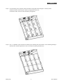
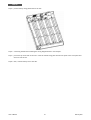
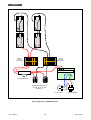
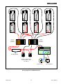
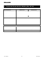
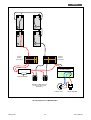
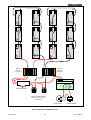
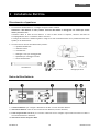
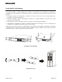
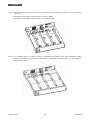
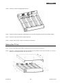
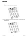
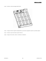
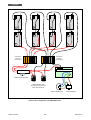
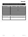
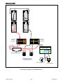
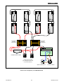
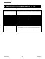
Battery Box
FBBEVDRT24/XX
FBBEVDRT48/XX
FBBEVDRT72/XX
User’s Manual
Manuale Utente
Index - Indice
User’s Manual - English ........................................................................ 1
1 Safety Warnings ............................................................................ 1
1.1 Product Disposal ......................................................................... 1
1.2 Lead Batteries ............................................................................ 1
2 Electrical Installation ...................................................................... 2
Unpacking & Inspection ...................................................................... 2
Rear Panel View .............................................................................. 2
Selecting Installation Position .............................................................. 3
Connecting with UPS and Other Battery Box ............................................. 4
3 Battery Installation ........................................................................ 4
Battery Box 24/48 Vdc ....................................................................... 4
Battery Box 72 Vdc ........................................................................... 6
4 Technical Characteristics Battery Box 24 Vdc ........................................ 9
5 Technical Characteristics Battery Box 48 Vdc ....................................... 12
6 Technical Characteristics Battery Box 72 Vdc ....................................... 15
Manuale Utente – Italiano .................................................................... 18
1 Avvisi di Sicurezza ........................................................................ 18
1.1 Smaltimento del Prodotto ............................................................. 18
1.2 Batterie al Piombo...................................................................... 18
2 Installazione Elettrica .................................................................... 19
Ricevimento e Ispezione ................................................................... 19
Retro del Box Batterie ..................................................................... 19
Scelta della Collocazione .................................................................. 20
Collegamento con l’UPS e con un altro Box Batterie .................................. 21
3 Montaggio delle Batterie................................................................. 21
Box Batterie 24/48 Vdc .................................................................... 21
Battery Box 72 Vdc ......................................................................... 23
4 Caratteristiche Tecniche Box Batterie 24 Vdc....................................... 26
5 Caratteristiche Tecniche Box Batterie 48 Vdc....................................... 29
6 Caratteristiche Tecniche Box Batterie 72 Vdc....................................... 32
© Copyright 2013 TECNOWARE s.r.l. All rights reserved.
All trademarks are property of their respective owners.
TECNOWARE s.r.l.
Via Montetrini, 2E – Molino del Piano – Florence – Italy
www.tecnoware.com
This manual has been printed and edited by TECNOWARE s.r.l.
May 2013 edition – version 1.0
ENGLISH
User’s Manual - English
1 Safety Warnings
Risk of electric shock: if all the batteries are connected, inside the Battery Box there are
internal parts which are at a high Voltage and are potentially dangerous, capable of
causing injury or death by electric shock.
Any repair or maintenance work must be performed exclusively by qualified technical
personnel authorized by TECNOWARE. TECNOWARE declines any responsibility if this
warning is disregarded.
Battery fuses shall only be replaced with fuses of same rating or equivalent.
Danger of explosion and fire if the batteries of the wrong type or number are used.
Do not dispose of batteries in a fire. The batteries may explode. Do not open or mutilate
batteries. Released electrolyte is harmful to the skin and eyes. It may be toxic
The Battey Box is compliant with the European Community directives. Hence it is marked:
1.1 Product Disposal
This Battery Box cannot be disposed as an urban waste, but must be treated as a separate waste. Any
violation is indictable with financial sanctions as per in force regulations.
An incorrect waste disposal or an improper use of the same or of any parts can be damaging for the
environment and for human health.
A correct waste disposal of products having the dustbin symbol marked by a cross help to avoid
negative consequences to the environment and to human health.
1.2 Lead Batteries
The Battery Box may contain lead acid, sealed, maintenance free batteries.
This kind of batteries, if handled by non-experienced personnel, can cause electric shock or shortcircuit.
For this reason the batteries can be removed only by qualified technical personnel, specialized and
authorized by Tecnoware. Tecnoware declines any responsibilities if this rule is not followed.
The batteries cannot be disposed as an urban waste, but must be treated in conformity with
2006/66/CE European Directive; any violation is indictable with financial sanctions as established into
2006/66/CE European Directive.
Battery Box
1
User’s Manual
ENGLISH
2 Electrical Installation
Unpacking & Inspection
1. Remove the battery box from the packing.
Note: The battery box is very heavy, be cautious when unpacking and lifting the unit to avoid injury.
Please inspect the unit. Be sure that nothing inside the package is damaged.
Please keep the original package in a safe place for future use.
2. Check the inside package
•
Battery box unit
•
Quick guide
•
Battery connection cable x 1
•
Ear x 2 & screw x 8
•
Feet x 2 sets
•
Input power cord
Feet
Battery connection cable
Ears
Screws
Rear Panel View
1. Battery Connector: connects to either UPS or 2nd battery box
2. Battery Breaker: Battery over-current protection Breaker (max current 50 A)
3. Grounded AC Input socket: connect it to AC line by the supplied power cord for recharging batteries.
4. Input Breaker
User’s Manual
2
Battery Box
ENGLISH
Selecting Installation Position
It is necessary to select a proper environment to install the unit, in order to minimize the possibility of damage to the
battery box and extend the life of the batteries. Please follow the instructions below:
1. Keep at least 20 cm clearance from the rear panel of the unit from the wall or other obstructions.
2. Do not block the air-flow to the ventilation openings of the unit.
3. Please ensure the installation site environmental conditions are in accordance with the unit’s working
specifications to avoid overheat and excessive moisture.
4. Do not place the unit in a dusty or corrosive environment or near any flammable objects.
5. This unit is not designed for outdoor use.
This unit can either be mounted in a Rack Cabinet (rack installation, see below), using the included ears and screws,
or placed vertically on the desk using the feet (tower installation, see below).
RACK INSTALLATION
TOWER INSTALLATION
Battery Box
3
User’s Manual
ENGLISH
Connecting with UPS and Other Battery Box
Follow below installation chart to connect with UPS and other battery box with included cable.
st
1 battery box
UPS
nd
2
battery box
3 Battery Installation
If your battery box is not installed with batteries, please follow proper procedure to put batteries inside of unit.
NOTE: make sure that the battery box is disconnected from the UPS before performing the following sequence of
operations.
Battery Box 24/48 Vdc
Step 1: open the package and place the battery box on a horizontal plane.
Step 2: remove the metal top cover of the battery box by unscrewing 8 screws present on the two sides (4 on the
right side + 4 on the left side), 3 screws on the top and 4 screws on the back side.
User’s Manual
4
Battery Box
ENGLISH
Step 3: once the battery box is opened, remove the battery fixing plates unscrewing the 2 screws present.
4 batteries inside: remove only the 2 battery fixing plates on the left.
8 batteries inside: remove all the four battery fixing plates.
Step 4: now, it is possible to put all batteries in battery box following the picture below. In the following drawing is
indicated the red fasten positions for the correct batteries placing (8 batteries).
Battery Box
5
User’s Manual
ENGLISH
Step 5: put the battery fixing plates back to the unit.
Step 6: connecting the batteries following the wiring diagram shown in next chapter.
Step 7: put metal top cover back to the unit. Close the frontal fixing plate and the two parts of the front panel and
secure it with screws.
Step 8: then, connect battery box to the UPS.
Battery Box 72 Vdc
Step 1: open the package and place the battery box on a horizontal plane.
Step 2: remove the metal top cover of the battery box by unscrewing 8 screws present on the two sides (4 on the
right side + 4 on the left side), 3 screws on the top and 4 screws on the back side.
User’s Manual
6
Battery Box
ENGLISH
Step 3: once the battery box is opened, remove the battery fixing plates unscrewing the 2 screws present.
6 batteries inside: remove only the 2 battery fixing plates on the left.
12 batteries inside: remove all the four battery fixing plates.
Step 4: now, it is possible to put all batteries in battery box following the picture below. In the following drawing is
indicated the red fasten positions for the correct batteries placing (12 batteries).
Battery Box
7
User’s Manual
ENGLISH
Step 5: put the battery fixing plates back to the unit.
Step 6: connecting the batteries following the wiring diagram shown in next chapter.
Step 7: put metal top cover back to the unit. Close the frontal fixing plate and the two parts of the front panel and
secure it with screws.
Step 8: then, connect battery box to the UPS.
User’s Manual
8
Battery Box
ENGLISH
4 Technical Characteristics Battery Box 24 Vdc
BATTERY BOX Model
Description
FBBEVDRT24/18
FBBEVDRT24/36
Battery Box compatible with UPS EVO DSP RT 1.3
Battery Type
Lead acid, sealed, free maintenance, 12 Vdc
Battery Specifications
12 Vdc – 9 Ah
Nominal Battery Voltage
24 Vdc
Number of batteries
4
8
Battery Charge Time (typical)
Expandable Autonomy
6-8 hours
Available, through external Battery Box (optional)
6 mm2
Cables Section
Breaker Max Current
50 A
Dimension (W x H x D)
Net Weight without Batteries
Net Weight with Batteries
ENVIRONMENTAL CONDITIONS
Storage Temperature Range
Operating Temperature Range
-25°C to +55°C (-15°C to 40°C recommended for longer Battery life)
0°C to +40°C (20°C to 25°C recommended for longer Battery life)
Relative Humidity Range
0% - 95% (non condensing)
Max. Altitude
Battery Box
3000 m
9
User’s Manual
ENGLISH
2
4
1
3
Parallel
Positive
connections
Parallel
Negative
Connections
BATTERY CHARGER
BATTERY BREAKER
N
BATTERY CONNECTORS (to
connect the UPS or other
Box Battery)
G
L
AC INPUT PLUG
CIRCUIT BREAKER
Wiring Diagrams for FBBEVDRT24/18
User’s Manual
10
Battery Box
ENGLISH
2
4
6
8
1
3
5
7
Parallel
Positive
connections
Parallel
Negative
connections
BATTERY CHARGER
BATTERY BREAKER
BATTERY CONNECTORS (to
connect the UPS or other
Box Battery)
N
G
L
AC INPUT PLUG
CIRCUIT BREAKER
Wiring Diagrams for FBBEVDRT24/36
Battery Box
11
User’s Manual
ENGLISH
5 Technical Characteristics Battery Box 48 Vdc
BATTERY BOX Model
Description
Battery Type
FBBEVDRT48/9
FBBEVDRT48/18
Battery Box compatible with UPS EVO DSP RT 2.6
Lead acid, sealed, free maintenance, 12 Vdc
Battery Specifications
12 Vdc – 9 Ah
Nominal Battery Voltage
Number of batteries
48 Vdc
4
8
Battery Charge Time (typical)
Expandable Autonomy
6-8 hours
Available, through external Battery Box (optional)
6 mm2
Cables Section
Breaker Max Current
50 A
Dimension (W x H x D)
Net Weight without Batteries
Net Weight with Batteries
ENVIRONMENTAL CONDITIONS
Storage Temperature Range
Operating Temperature Range
-25°C to +55°C (-15°C to 40°C recommended for longer Battery life)
0°C to +40°C (20°C to 25°C recommended for longer Battery life)
Relative Humidity Range
0% - 95% (non condensing)
Max. Altitude
User’s Manual
3000 m
12
Battery Box
ENGLISH
2
3
1
4
Parallel
Positive
Connections
Parallel
Negative
Connections
BATTERY CHARGER
BATTERY BREAKER
N
BATTERY CONNECTORS (to
connect the UPS or other
Box Battery)
G
L
AC INPUT PLUG
CIRCUIT BREAKER
Wiring Diagrams for FBBEVDRT48/9
Battery Box
13
User’s Manual
ENGLISH
2
3
6
7
1
4
5
8
Parallel
Positive
Connections
Parallel
Negative
Connections
BATTERY CHARGER
BATTERY BREAKER
N
BATTERY CONNECTORS (to
connect the UPS or other
Box Battery)
G
L
AC INPUT PLUG
CIRCUIT BREAKER
Wiring Diagrams for FBBEVDRT48/18
User’s Manual
14
Battery Box
ENGLISH
6 Technical Characteristics Battery Box 72 Vdc
BATTERY BOX Model
Description
Battery Type
FBBEVDRT72/9
FBBEVDRT72/18
Battery Box compatible with UPS EVO DSP RT 4.0
Lead acid, sealed, free maintenance, 12 Vdc
Battery Specifications
12 Vdc – 9 Ah
Nominal Battery Voltage
Number of batteries
72 Vdc
6
12
Battery Charge Time (typical)
Expandable Autonomy
6-8 hours
Available, through external Battery Box (optional)
6 mm2
Cables Section
Breaker Max Current
50 A
Dimension (W x H x D)
Net Weight without Batteries
Net Weight with Batteries
ENVIRONMENTAL CONDITIONS
Storage Temperature Range
Operating Temperature Range
-25°C to +55°C (-15°C to 40°C recommended for longer Battery life)
0°C to +40°C (20°C to 25°C recommended for longer Battery life)
Relative Humidity Range
0% - 95% (non condensing)
Max. Altitude
Battery Box
3000 m
15
User’s Manual
ENGLISH
3
4
2
5
1
6
Parallel
Positive
Connections
Parallel
Negative
Connections
BATTERY CHARGER
BATTERY BREAKER
N
BATTERY CONNECTORS (to
connect the UPS or other
Box Battery)
G
L
AC INPUT PLUG
CIRCUIT BREAKER
Wiring Diagrams for FBBEVDRT72/9
User’s Manual
16
Battery Box
ENGLISH
3
4
9
10
2
5
8
11
1
6
7
12
Parallel
Positive
Connections
Parallel
Negative
Connections
BATTERY CHARGER
BATTERY BREAKER
N
BATTERY CONNECTORS (to
connect the UPS or other
Box Battery)
G
L
AC INPUT PLUG
CIRCUIT BREAKER
Wiring Diagrams for FBBEVDRT72/18
Battery Box
17
User’s Manual
ITALIANO
Manuale Utente – Italiano
1 Avvisi di Sicurezza
Elevato rischio di shock elettrico: se nel Box Batterie sono state montate le batterie,
all’interno del Box Batterie sono presenti pericolose tensioni che possono provocare
lesioni o morte per shock elettrico.
Interventi tecnici di qualsiasi tipo devono essere compiuti solo da personale tecnico
specializzato ed autorizzato da TECNOWARE. In caso contrario TECNOWARE declina ogni
sua responsabilità.
I fusibili Batteria devono essere sostituiti solo con fusibili uguali o con le stesse
caratteristiche elettriche.
Pericolo di esplosione o di incendio se si utilizzano batterie di tipo sbagliato o un numero
errato di batterie.
Non avvicinare le batterie al fuoco. Le batterie possono esplodere. Non aprire o
danneggiare le batterie. L’elettrolita contenuto nelle batterie che può fuoriuscire è
nocivo alla pelle e agli occhi.
Il Box Batterie è conforme alle Direttive Europee. Quindi ha il marchio:
1.1 Smaltimento del Prodotto
Il prodotto Box Batterie non può essere smaltito come rifiuto urbano, ma deve esserlo tramite raccolta
separata; qualsiasi violazione è punita con sanzioni pecuniarie ai sensi delle vigenti norme.
Lo smaltimento non corretto del prodotto, o l’uso improprio dello stesso o di sue parti, è dannoso per
l’ambiente e per la salute umana.
Il corretto smaltimento dei prodotti recanti il simbolo del bidone segnato da una croce aiuta ad
evitare possibili conseguenze negative per l’ambiente e la salute umana.
1.2 Batterie al Piombo
Il prodotto Box Batterie può contenere batterie al piombo acido, ermetiche, senza manutenzione.
Tali batterie, se manovrate da personale inesperto, possono essere causa di shock elettrico e di alte
correnti di cortocircuito.
Per questo motivo la rimozione delle batterie può essere compiuto solo da personale tecnico
specializzato ed autorizzato da Tecnoware. In caso contrario Tecnoware declina ogni sua
responsabilità.
Le batterie non possono essere smaltite come rifiuto urbano, ma devono essere smaltite nelle
modalità previste dalla direttiva europea 2006/66/CE; qualsiasi violazione è punita con sanzioni
pecuniarie ai sensi della direttiva stessa.
Manuale Utente
18
Box Batterie
ITALIANO
2 Installazione Elettrica
Ricevimento e Ispezione
1. Al ricevimento del Box Batterie, si consiglia di toglierlo subito l'imballo.
Attenzione: il Box Batterie è molto pesante: sollevarlo dall’imballo e maneggiarlo con cautela per evitare
danni a persone o cose.
Controllare subito lo stato del Box Batterie. In caso di danni dovuti al trasporto, annotarli sulla bolla di
accompagnamento merce e contattare subito il fornitore.
Si consiglia di conservare l’imballo originale in luogo sicuro nell’eventualità futura che il prodotto dovesse essere
spedito per la manutenzione.
2. Accertarsi che all’interno dell’imballo siano presenti:
•
Il prodotto Box Batterie
•
Il manuale utente
•
Il Cavo Batterie
•
2 maniglie e 8 viti per montaggio Rack
•
2 piedistalli per montaggio verticale
•
Cavo di alimentazione
Piedistalli
Cavo Batterie
Viti per Rack
Maniglie per Rack
Retro del Box Batterie
1. Connettore Batterie: per collegare il Box Batteria all’UPS e/o ad un altro Box Batterie.
2. Interruttore Batterie: scatta in caso di sovracorrente Batteria (corrente max 50 A).
3. Presa d’Ingresso Rete con terra: per ricaricare le batterie occorre collegare la presa alla linea elettrica tramite il
cavo di alimentazione in dotazione.
4. Interruttore termico d’Ingresso Rete.
Box Batterie
19
Manuale Utente
ITALIANO
Scelta della Collocazione
È necessario scegliere il giusto ambiente per installare il Box Batterie, per minimizzare la possibilità di
danneggiamenti e per estendere la vita delle batterie. Perciò si consiglia di prestare particolare attenzione ai punti
seguenti:
1. È necessario lasciare uno spazio libero di almeno 20 cm sia sul fronte che sul retro del Box Batterie per
permetterne una sufficiente areazione.
2. Consultare comunque il capitolo “Caratteristiche Tecniche” per i requisiti ambientali e controllare che il luogo
scelto rientri in tali specifiche.
3. Non posizionare l’unità in un ambiente polveroso, corrosivo o vicino ad oggetti infiammabili.
4. Il Box Batterie è progettato per operare in ambienti chiusi (come ad esempio gli uffici). Si consiglia perciò
d’installarlo in un luogo privo di umidità, polvere e fumo eccessivi.
Questa unità può essere sia montata in un Armadio Rack (vedi la figura sotto “Montaggio in Armadio Rack), utilizzando
le maniglie rack con relative viti, di corredo al prodotto, oppure collocata in posizione Tower (vedi la figura sotto
“Collocazione Tower”, usando i piedistalli di corredo al prodotto).
Montaggio in Armadio Rack
Collocazione Tower
Manuale Utente
20
Box Batterie
ITALIANO
Collegamento con l’UPS e con un altro Box Batterie
Nella figura sotto riportata è descritto il modo di collegamento con l’UPS e con un eventuale altro Box Batterie. Per le
connessioni utilizzare sempre il cavo batterie di corredo.
Box Batterie 1
UPS
Box Batterie 2
3 Montaggio delle Batterie
Se il Box Batterie non ha le batterie, per montare in maniera corretta le batterie al suo interno attenersi
scrupolosamente alla istruzioni riportare sotto.
ATTENZIONE: prima di eseguire le operazioni sotto descritte, accertarsi che il Box Batterie sia scollegato
dall’UPS.
Box Batterie 24/48 Vdc
Step 1: estrarre il Box Batterie dall’imballo e posizionarlo su un piano di lavoro orizzontale.
Step 2: rimuovere il coperchio metallico superiore svitando le 8 viti presenti sui lati (4 sul lato destro e 4 sul lato
sinistro), le 3 viti sul lato frontale e le 4 viti sul retro.
Box Batterie
21
Manuale Utente
ITALIANO
Step 3: tolto il coperchio, rimuovere le staffe che servono per bloccare le batterie, svitando le 2 viti che fermano
ogni staffa.
Box Batterie con 4 batterie: rimuovere solo le 2 staffe a sinistra.
Box Batterie con 8 batterie: rimuovere tutte e 4 le staffe presenti.
Step 4: ora è possibile inserire le batterie nel box. La posizione delle batterie deve essere esattamente quella
illustrate nella figura sottostante (caso con 8 batterie). La posizione del reoforo rosso (+) di ogni batteria è
indicata da una freccia.
Manuale Utente
22
Box Batterie
ITALIANO
Step 5: rimontare le staffe di fissaggio delle batterie.
Step 6: collegare le batterie seguendo scrupolosamente gli schemi dei collegamenti riportati nel prossimo capitolo.
Step 7: rimontare il coperchio metallico superiore del box.
Step 8: collegare il box all’UPS, tramite il cavo batterie in dotazione.
Battery Box 72 Vdc
Step 1: estrarre il Box Batterie dall’imballo e posizionarlo su un piano di lavoro orizzontale.
Step 2: rimuovere il coperchio metallico superiore svitando le 8 viti presenti sui lati (4 sul lato destro e 4 sul lato
sinistro), le 3 viti sul lato frontale e le 4 viti sul retro.
Box Batterie
23
Manuale Utente
ITALIANO
Step 3: tolto il coperchio, rimuovere le staffe che servono per bloccare le batterie, svitando le 2 viti che fermano
ogni staffa.
Box Batterie con 6 batterie: rimuovere solo le 2 staffe a sinistra.
Box Batterie con 12 batterie: rimuovere tutte e 4 le staffe presenti.
Step 4: ora è possibile inserire le batterie nel box. La posizione delle batterie deve essere esattamente quella
illustrate nella figura sottostante (caso con 12 batterie). La posizione del reoforo rosso (+) di ogni batteria è
indicata da una freccia.
Manuale Utente
24
Box Batterie
ITALIANO
Step 5: rimontare le staffe di fissaggio delle batterie.
Step 6: collegare le batterie seguendo scrupolosamente gli schemi dei collegamenti riportati nel prossimo capitolo.
Step 7: rimontare il coperchio metallico superiore del box.
Step 8: collegare il box all’UPS, tramite il cavo batterie in dotazione.
Box Batterie
25
Manuale Utente
ITALIANO
4 Caratteristiche Tecniche Box Batterie 24 Vdc
Modello BOX BATTERIE
Descrizione
FBBEVDRT24/18
Box Batterie compatibile con UPS EVO DSP RT 1.3
Tipo Batterie
Piombo acido, sigillate, senza manutenzione
Specifiche Batterie
12 Vdc – 9 Ah
Tensione Nominale Batterie
Numero di Batterie
24 Vdc
4
Tempo di ricarica Batterie (Tipico)
Espansione Autonomia
FBBEVDRT24/36
8
6-8 ore
Disponibile, tramite ulteriore Box Batterie (opzionale)
6 mm2
Sezione cavi
Max Corrente Batteria
50 A
Dimensioni (L x H x P)
Peso netto senza Batterie
Peso netto con Batterie
CONDIZIONI AMBIENTALI OPERATIVE
Range temperatura di stoccaggio
Da -25°C a +55°C
(è raccomandato da +15°C a +40°C per avere una più lunga vita delle batterie)
Range Temperatura di lavoro
Da 0°C a +40°C
(è raccomandato da +20°C a +25°C per avere una più lunga vita delle batterie)
Range umidità relativa
0% - 95% (senza condensazione)
Altitudine massima
Manuale Utente
3000 metri
26
Box Batterie
ITALIANO
2
4
1
3
Connessioni
Parallele
Lato Positivo
Connessioni
Parallele
Lato Negativo
CARICA BATTERIA
INTERRUTTORE BATTERIA
CONNETTORI BATTERIE
(per collegare all’UPS o ad
un’altro Box Batterie)
N
G
L
PRESA D’INGRESSO AC
FUSIBILE TERMICO
Schema dei collegamenti per FBBEVDRT24/18
Box Batterie
27
Manuale Utente
ITALIANO
2
4
6
8
1
3
5
7
Connessioni
Parallele
Lato Positivo
Connessioni
Parallele
Lato Negativo
CARICA BATTERIA
INTERRUTTORE BATTERIA
CONNETTORI BATTERIE
(per collegare all’UPS o ad
un’altro Box Batterie)
N
G
L
PRESA D’INGRESSO AC
FUSIBILE TERMICO
Schema dei collegamenti per FBBEVDRT24/36
Manuale Utente
28
Box Batterie
ITALIANO
5 Caratteristiche Tecniche Box Batterie 48 Vdc
Modello BOX BATTERIE
Descrizione
Tipo Batterie
FBBEVDRT48/9
Box Batterie compatibile con UPS EVO DSP RT 2.6
Piombo acido, sigillate, senza manutenzione
Specifiche Batterie
12 Vdc – 9 Ah
Tensione Nominale Batterie
Numero di Batterie
48 Vdc
4
Tempo di ricarica Batterie (Tipico)
Espansione Autonomia
FBBEVDRT48/18
8
6-8 ore
Disponibile, tramite ulteriore Box Batterie (opzionale)
6 mm2
Sezione cavi
Max Corrente Batteria
50 A
Dimensioni (L x H x P)
Peso netto senza Batterie
Peso netto con Batterie
CONDIZIONI AMBIENTALI OPERATIVE
Range temperatura di stoccaggio
Da -25°C a +55°C
(è raccomandato da +15°C a +40°C per avere una più lunga vita delle batterie)
Range Temperatura di lavoro
Da 0°C a +40°C
(è raccomandato da +20°C a +25°C per avere una più lunga vita delle batterie)
Range umidità relativa
0% - 95% (senza condensazione)
Altitudine massima
Box Batterie
3000 metri
29
Manuale Utente
ITALIANO
2
3
1
4
Connessioni
Parallele
Lato Positivo
Connessioni
Parallele
Lato Negativo
CARICA BATTERIA
INTERRUTTORE BATTERIA
CONNETTORI BATTERIE
(per collegare all’UPS o ad
un’altro Box Batterie)
N
G
L
PRESA D’INGRESSO AC
FUSIBILE TERMICO
Schema dei collegamenti per FBBEVDRT48/9
Manuale Utente
30
Box Batterie
ITALIANO
2
3
6
7
1
4
5
8
Connessioni
Parallele
Lato Positivo
Connessioni
Parallele
Lato Negativo
CARICA BATTERIA
INTERRUTTORE BATTERIA
CONNETTORI BATTERIE
(per collegare all’UPS o ad
un’altro Box Batterie)
N
G
L
PRESA D’INGRESSO AC
FUSIBILE TERMICO
Schema dei collegamenti per FBBEVDRT48/18
Box Batterie
31
Manuale Utente
ITALIANO
6 Caratteristiche Tecniche Box Batterie 72 Vdc
Modello BOX BATTERIE
Descrizione
FBBEVDRT72/9
Box Batterie compatibile con UPS EVO DSP RT 2.6
Tipo Batterie
Piombo acido, sigillate, senza manutenzione
Specifiche Batterie
12 Vdc – 9 Ah
Tensione Nominale Batterie
Numero di Batterie
72 Vdc
6
Tempo di ricarica Batterie (Tipico)
Espansione Autonomia
FBBEVDRT72/18
12
6-8 ore
Disponibile, tramite ulteriore Box Batterie (opzionale)
6 mm2
Sezione cavi
Max Corrente Batteria
50 A
Dimensioni (L x H x P)
Peso netto senza Batterie
Peso netto con Batterie
CONDIZIONI AMBIENTALI OPERATIVE
Range temperatura di stoccaggio
Da -25°C a +55°C
(è raccomandato da +15°C a +40°C per avere una più lunga vita delle batterie)
Range Temperatura di lavoro
Da 0°C a +40°C
(è raccomandato da +20°C a +25°C per avere una più lunga vita delle batterie)
Range umidità relativa
0% - 95% (senza condensazione)
Altitudine massima
Manuale Utente
3000 metri
32
Box Batterie
ITALIANO
3
4
2
5
1
6
Connessioni
Parallele
Lato Positivo
Connessioni
Parallele
Lato Negativo
CARICA BATTERIA
INTERRUTTORE BATTERIA
CONNETTORI BATTERIE
(per collegare all’UPS o ad
un’altro Box Batterie)
N
G
L
PRESA D’INGRESSO AC
FUSIBILE TERMICO
Schema dei collegamenti per FBBEVDRT72/9
Box Batterie
33
Manuale Utente
ITALIANO
3
4
9
10
2
5
8
11
1
6
7
12
Connessioni
Parallele
Lato Positivo
Connessioni
Parallele
Lato Negativo
CARICA BATTERIA
INTERRUTTORE BATTERIA
CONNETTORI BATTERIE
(per collegare all’UPS o ad
un’altro Box Batterie)
N
G
L
PRESA D’INGRESSO AC
FUSIBILE TERMICO
Schema dei collegamenti per FBBEVDRT72/18
Manuale Utente
34
Box Batterie
ITALIANO
Box Batterie
35
Manuale Utente
ITALIANO
Manuale Utente
36
Box Batterie
TECNOWARE s.r.l.
www.tecnoware.com
38


![[ITA] ERA LCD 1.5 - 2.0 - 2.6 v.3.0](http://vs1.manualzilla.com/store/data/006158360_1-723f61f8946d2d729252a86ec11afdef-150x150.png)

![[ENG] EVO DSP TM 10-30 kVA User Manual v. 2.0](http://vs1.manualzilla.com/store/data/005715238_1-26b73917878f712f842422018d03a475-150x150.png)