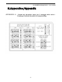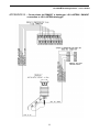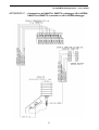
1
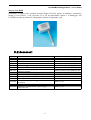
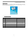
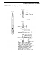
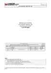
Termoigrometri con
uscita analogica
-
Termohygrometers with
analogue output
Manuale utente
User’s manual
Versione 04/12/2008
Update 04/12/2008
Cod. INSTUM_00446_it-en
Termoigrometri LSI LASTEM – Manuale utente
LSI LASTEM Thermohygrometers – User’s manual
Sommario
1. Descrizione.......................................................................................................................................3
1.1. Modelli......................................................................................................................................3
2. Caratteristiche tecniche....................................................................................................................4
3. Istruzioni per il montaggio..............................................................................................................5
3.1. Assemblaggio meccanico .........................................................................................................5
3.2. Accessori...................................................................................................................................6
3.3. Configurazione datalogger LSI LASTEM................................................................................7
4. Note sull’impiego.............................................................................................................................8
5. Verifiche funzionali..........................................................................................................................9
5.1. Verifica visiva esterna...............................................................................................................9
5.2. Verifica visiva interna...............................................................................................................9
5.3. Verifica operativa......................................................................................................................9
5.4. Verifica funzionale....................................................................................................................9
6. Manutenzione.................................................................................................................................10
6.1. Pulizia dello schermo antiradiante...........................................................................................10
6.2. Pulizia degli elementi di misurazione......................................................................................10
6.3. Pulizia del filtro poroso...........................................................................................................10
6.4. Come asciugare il filtro poroso...............................................................................................10
6.5. Sostituzione dell’elemento sensibile.......................................................................................10
7. Dichiarazione di conformità CE / Declaration of CE conformità..................................................20
8. Appendice/Appendix......................................................................................................................21
Si veda pag. 11 per la versione in lingua inglese del manuale.
See pag.11 for user’s manual in English language.
2
Termoigrometri LSI LASTEM – Manuale utente
LSI LASTEM Thermohygrometers – User’s manual
1.Descrizione
Il termoigrometro è uno strumento che misura la temperatura e l’umidità relativa dell’aria.
La LSI LASTEM propone una serie di sonde precise ed affidabili, adatte per la misura continua in
ambienti esterni severi, con presenza di forti escursioni termiche e idrometriche ed elevata
radiazione solare. Una caratteristica importante di questa linea di sensori è la facile
intercambiabilità del solo elemento sensibile termoigrometrico, che rende semplice ed immediata la
normale manutenzione programmata ed elimina la necessità di calibrazione (la figura sotto illustra
la componentistica della sonda: filtro poroso, elemento sensibile…).
Da segnalare nella versione a ventilazione forzata la presenza di una ventola che assicura un
continuo ricambio d’aria attorno al sensore eliminando l’errore nella temperatura dovuto al calore
radiante.
Filtro poroso
Elemento
sensibile
1.1.Modelli
Descrizione
Alimentazione
Uscita
Sensore di temperatura ed umidità relativa con uscita analogica,
completo di schermo antiradiante a ventilazione naturale.
Sensore di temperatura ed umidità relativa con uscita analogica,
completo di schermo antiradiante a ventilazione forzata.
Sensore di temperatura ed umidità relativa con uscita analogica
Cod.
12 V=
24 V≈
Analogica* Analogica*
DMA585
DMA575
DMA569
DMA567
DME785
DME775
* = uscita programmabile localmente: 0/4:20 mA, 0/0.2:1 V, 0/1:5 V, 0/60:300 mV (default 4:20 mA)
3
Termoigrometri LSI LASTEM – Manuale utente
LSI LASTEM Thermohygrometers – User’s manual
2.Caratteristiche tecniche
Campo di misura
Elemento sensibile
Sostituzione
dell’elemento
sensibile
Accuratezza elemento sensibile
(Ripetibilità + isteresi)
Accuratezza elettronica
Risoluzione
Tempo di risposta
(Elemento sensibile)
Stabilità a lungo termine
Dipendenza di temperatura
(6 ÷45 °C / 11 ÷90% RH)
Temperatura di utilizzo
Uscita elettrica
Temperatura
Selezionabile
(-30÷70 °C, -50÷50 °C, 0÷100 °C,
-50÷100 °C)
Pt 100 1/3 DIN-B
Alimentazione
Consumo Elettrico
Compatibilità CE
Protezione elettrica
Alloggiamento
Peso
Cavo di Connessione
Umidità relativa
0 ÷ 100 %
Capacitivo
Connettore plug-in ML3021
1,5% (5 ÷ 95%, 23 °C)*
2%(<5, >95%, 23 °C)*
n.a.
0.5%
±0,2 °C (0 °C)
±0.15%
0,06 °C
10s
n.a.
< 1% l’anno
n.a.
Max ± 1,5%
-40 ÷ 95 °C
Analogica
0/4:20 mA, 0/0.2:1 V, 0/1:5 V, 0/60:300 mV (default 4:20 mA)
DMA575-DMA567-DME775: 12 Vcc
DMA585-DMA569-DME785: 24 Vca
DMA575-DMA585-DME775-DME785: max 1.5W
DMA567-DMA569: max 3W
EMC EN 61326-1 2006
Tranzorb su uscita ed alimentazione
Plastica delrin
e alluminio (DME775-DME785)
DMA567-DMA569: 1900g
DMA575-DMA585: 1250g
DME775-DME785: 650g
Non fornito, vedi accessori. Mod. DWA5… (6 fili + schermo)
* = stessi valori per il punto di rugiada
4
Termoigrometri LSI LASTEM – Manuale utente
LSI LASTEM Thermohygrometers – User’s manual
3. Istruzioni per il montaggio
Selezionare una località le cui condizioni siano rappresentative dell’ambiente esaminato.
I termoigrometri devono essere montati in località dove le condizioni morfologiche della terra, le
strutture urbane e le condizioni ambientali rispecchino il più possibile le condizioni generali della
località in cui si desidera eseguire le misure.
È importante che, nelle aree vicine all’installazione, non vi siano delle strutture che possano
irradiare calore (pavimenti in cemento, asfalto, muri, ecc.). Il termoigrometro dovrebbe essere
installato ad una distanza di 1,5 - 2 m. dal suolo (vedere WMO n° 8 parte 2).
3.1.Assemblaggio meccanico
Sensori serie DMA
Sistemare il collare di supporto DYA051 sul palo nell’altezza desiderata (di solito 1,5 - 2 m.) e
avvitare le viti (chiave a brugola n. 6).
Fissare lo strumento al collare DYA051 e connetterlo, tramite il cavo DWA5.. (vedi Accessori
§3.2), ad un alimentatore idoneo e al datalogger LSI LASTEM secondo gli schemi di collegamento
riportati in Appendice (§8).
5
Termoigrometri LSI LASTEM – Manuale utente
LSI LASTEM Thermohygrometers – User’s manual
Sensori serie DME
Posizionare il sensore entro condotte (tramite flangia CLO306) oppure in ambiente; connetterlo,
tramite il cavo DWA5.. (vedi Accessori §3.2), ad un alimentatore idoneo e al datalogger LSI
LASTEM secondo gli schemi di collegamento riportati in Appendice (§8).
3.2.Accessori
Codice
DWA510
DWA525
DWA526
DWA527
DYA051
MG2251
ML3021
MC4112
MM6101
MM0316
MM0315
CLO306
CLO310
CLO312
Descrizione
Cavo L.10 m con connettore
Cavo L.25 m con connettore
Cavo L.50 m con connettore
Cavo L.100 m con connettore
Collare fissaggio sensore a palo Ø50 mm
Connettore femmina volante sciolto
Ricambio cartuccia plug-in per sostituzione
elemento sensibile
Ricambio raccordo sonda-filtro poroso
Ricambio filtro poroso (cappuccio)
Ventola per schermo a ventilazione forzata (24Vac)
Ventola per schermo a ventilazione forzata (12Vcc)
Flangia scorrevole per fissaggio sonde Ø18 mm
in condotte
Supporto per fissaggio sonde Ø18 mm a muri
Passacavo con dado M32x1,5 per fissaggio
sonde Ø18 mm
6
Modelli coinvolti
DMA567-569-575-585, DME775-785
DMA567-569-575-585, DME775-785
DMA567-569-575-585, DME775-785
DMA567-569-575-585, DME775-785
DMA567-569-575-585, DME775-785
DMA567-569-575-585, DME775-785
DMA567-569-575-585, DME775-785
DMA567-569-575-585, DME775-785
DMA567-569-575-585, DME775-785
DMA569
DMA567
DME775-785
DME775-785
DME775-785
Termoigrometri LSI LASTEM – Manuale utente
LSI LASTEM Thermohygrometers – User’s manual
3.3.Configurazione datalogger LSI LASTEM
Babuc/ABC
Dopo la connessione elettrica del sensore (vedere disegni in Appendice §8), dal menu principale di
Babuc ABC scegliere Sistema/Configura Ingressi/Configura.
Inserire il codice operativo (CodOp) 077 per la temperatura e successivamente inserire l’ingresso
della morsettiera nel quale il sensore è collegato. Ripetere la stessa sequenza per l’umidità relativa
(codice operativo: 031).
Fare attenzione ai parametri di ingegnerizzazione dei codici operativi da inserire; essi devono essere
in accordo con quanto settato (uscita elettrica e campi di misura) tramite switch nella scatola della
sonda.
Ricordarsi inoltre che se si vuole impostare un segnale in uscita in corrente bisogna inserire una
resistenza da 50 Ω tra gli ingressi del segnale nella morsettiera dell’acquisitore.
Per maggiori dettagli consultare il manuale operativo di Babuc ABC (INSTUM_00063 o MW6050
riportato sul CD prodotti di LSI LASTEM – MW6501).
E-Log
Nel programma di configurazione 3DOM, dopo aver scelto una configurazione scegliere Misure
dalla finestra Parametri generali posizionata sulla sinistra e fare poi click sul bottone Aggiungi
posizionato a destra. Appare ora una libreria di sensori, dalla quale scegliere il codice del sensore da
inserire. Fare attenzione ai parametri inseriti nel menu Parametri della finestra Proprietà della
misura: essi devono essere in accordo con quanto settato (uscita elettrica e campi di misura) tramite
switch nella scatola della sonda.
Il programma assegna automaticamente il sensore ad un ingresso libero. La connessione elettrica
deve poi rispettare questa assegnazione.
Ricordarsi inoltre che se si vuole impostare un segnale in uscita in corrente bisogna inserire una
resistenza da 50 Ω tra gli ingressi del segnale nella morsettiera dell’acquisitore.
Per maggiori dettagli consultare il manuale operativo di E-Log (INSTUM_00013), la guida rapida
E-Log Quick Start (INSTUM_00068) e il manuale utente del software 3DOM (SWUM_00286)
presenti sul CD prodotti di LSI LASTEM MW6501.
7
Termoigrometri LSI LASTEM – Manuale utente
LSI LASTEM Thermohygrometers – User’s manual
4.Note sull’impiego
Misura dell’umidità in ambienti ad alta temperatura
Nelle zone tropicali molto umide, è possibile che i valori di umidità acquisiscano un campo
dinamico molto basso vicino a condizioni di saturazione. In certi periodi dell’anno, queste
condizioni sono riscontrate durante brevi periodi anche nelle zone più miti.
In queste condizioni l’elemento igrocapacitivo può essere bagnato (dalla rugiada) senza aver il
tempo di asciugarsi per riacquistare le sue capacità di misura. In questo caso, anche se il valore
dell’umidità diminuisce, la misura dell’umidità si stabilizza intorno al valore di saturazione o viene,
in ogni caso, sottovalutata.
Sono possibili due condizioni. La prima si riferisce ad ogni tipo di sensore di umidità di “tipo a
scambio”; la seconda è tipica dei sensori di umidità di tipo a misura capacitiva:
a) Lo strato di rugiada sopra l’elemento di misura può raggiungere 0,25 mm. La teoria di Penman
ritiene che sono necessarie 8 ore per asciugare questo strato (a 30°C, 80 RH% in assenza di
velocità dell’aria), oppure 4 ore (a 30°C, 60 RH% in assenza di velocità dell’aria). Questi
periodi possono essere più brevi in caso di ventilazione forzata (minimo 1,5 m/s).
b) I fabbricanti di elementi igrocapacitivi suggeriscono che un persistente livello di umidità
sull’elemento potrebbe dare origine ad un fenomeno secondario di assorbimento, nonché
causare uno sbalzo temporaneo della misura dell’umidità pari a circa +6%. Questo errore
sparisce quando l’elemento viene esposto per alcune ore a valori di umidità più bassi.
Queste considerazioni confermano che l’elemento igrocapacitivo può essere utilizzato quando i
valori di umidità raggiungono un campo dinamico sufficiente da permettere che il sensore si
aggiusti in base alla condizione di “stress”.
Influenza del filtro poroso in condizioni di forti umidità
I termoigrometri con filtro poroso hanno sensibilmente maggiore inerzia. Inoltre in ambiente
fortemente oscillante con alti valori di umidità, non è detto che la misura si porti agli estremi
dell’ambiente stesso. In caso di ambiente stabile, la misura, se pur lentamente, è comunque eseguita
correttamente.
Per quanto riguarda i filtri, è plausibile che l’inerzia della misura sia tanto maggiore quanto più
stretti sono i pori del filtro, quindi in condizioni di parziale otturazione è possibile che il sensore
non riesca a seguire le naturali oscillazioni dell’umidità ambientale, e produca quindi misurazioni
smorzate. Essendo di norma installati in ambienti esterni, si consiglia quindi di mantenere più pulito
possibile il filtro poroso per non falsare la misurazione; ove necessario procedere con la
sostituzione.
8
Termoigrometri LSI LASTEM – Manuale utente
LSI LASTEM Thermohygrometers – User’s manual
5.Verifiche funzionali
5.1.Verifica visiva esterna
1. Controllare che lo schermo antiradiante esterno sia ben pulito e privo di ammaccature
(infatti più risulta pulito più aumenta la sua capacità riflessiva).
2. Controllare il corretto funzionamento della ventola (nei modelli a ventilazione forzata).
5.2.Verifica visiva interna
Estrarre il sensore dallo schermo e:
1. Controllare che il filtro poroso a protezione dell’elemento sensibile sia pulito (vedere §6.3);
2. Controllare che l’elemento igrocapacitivo sia ben pulito. Controllare (se possibile anche
mediante ausilio di una lente d’ingrandimento) l’eventuale presenza di polvere o rugiada
sulla piastra capacitiva. Verificare inoltre l’assenza di ossidazioni sui contatti. Non toccare
la piastra capacitiva con le mani. Se necessario, pulire l’elemento (vedere §6.2).
5.3.Verifica operativa
1. Misurare la temperatura e umidità ambientale con un termoigrometro di riferimento.
2. Confrontare la misura di riferimento con la sonda in fase di test. Verificare che i valori della
sonda in fase di test si trovino all’interno dell’intervallo di Accuratezza (vedere § 2).
5.4.Verifica funzionale
Per verificare l’effettiva funzionalità della sonda:
1. Disconnettere il cavo della sonda dall’apparecchio;
2. Alimentare il sensore sui fili marrone (+) e blu (-) tramite apposito alimentatore;
3. Misurare, mediante tester in V, tra i fili blu e rosso, un’uscita compresa tra 0 e 1 V per il
segnale di umidità;
4. Per il segnale di temperatura, misurare, mediante ohmetro, un’uscita pari a:
- 0 Ω tra le coppie di fili nero-giallo e verde-bianco,
- un valore compreso tra 100 e110 Ω tra le combinazioni incrociate tra le coppie (es: neroverde, nero-bianco …) a seconda della temperatura ambiente; 107,8 Ω a 20°C con un
delta di ± 0,39 Ω/°C.
In presenza di segnale su entrambe le uscite, il sensore supera il test funzionale.
9
Termoigrometri LSI LASTEM – Manuale utente
LSI LASTEM Thermohygrometers – User’s manual
6.Manutenzione
6.1.Pulizia dello schermo antiradiante
Pulire lo schermo antiradiante esterno con uno spazzolino o con straccio inumidito.
6.2.Pulizia degli elementi di misurazione
1.
2.
3.
4.
Scollegare il cavo dalla sonda;
Svitare le guarnizioni del cavo nella parte inferiore ed estrarre il sensore dallo schermo;
Svitare la protezione bianca del filtro poroso;
Pulire la superficie del Pt100 (elemento di misurazione della temperatura) con un piccolo
pennello molto morbido;
5. Pulire la piastra capacitiva con un piccolo pennello molto morbido imbevuto in acqua
distillata. ATTENZIONE: attendere 2-3 ore prima di eseguire delle misure. È possibile
ridurre questo tempo se si lascia l’elemento in un posto asciutto o esposto ad una corrente di
aria fredda per alcune ore.
6.3.Pulizia del filtro poroso
Spruzzare la parte interna del filtro con dell’aria fredda.
6.4.Come asciugare il filtro poroso
A causa degli elevati e continui valori di umidità tipici delle zone tropicali, è possibile riscontrare la
formazione di umidità attorno all’elemento all’interno della protezione del filtro poroso. Questo
fenomeno può consumare l’elemento capacitivo a causa della stabilizzazione degli alti valori di
umidità anche se, dopo un certo periodo, l’umidità ambientale diminuisce. In questo caso, spruzzare
il filtro con dell’aria fredda.
6.5.Sostituzione dell’elemento sensibile
La procedura di sostituzione dell’elemento sensibile è assai semplice (vedere §8 Appendice D).
1.
2.
3.
4.
Svitare le guarnizioni del cavo nella parte inferiore ed estrarre il sensore dallo schermo.
Svitare la protezione bianca del filtro poroso
Svitare il coperchio protettore come indicato nella figura sottostante
Estrarre l’elemento sensibile e sostituirlo con uno nuovo (codice LSI LASTEM ML3021)
prestando attenzione ad infilare i tre contatti esterni del circuito sui tre esterni del sensore.
LSI LASTEM consiglia di effettuare i controlli e le pulizie sopraindicate con cadenza minima
semestrale; propone inoltre la sostituzione dell’elemento sensibile e del filtro poroso con una
cadenza connessa al luogo di installazione (in condizioni estreme di umidità, inquinamento,
presenza di polveri e sostanze chimiche l’elemento sensibile subisce un deterioramento più
rapido rispetto a quello installato in località con condizioni ottimali). E’ comunque buona norma
una sostituzione con cadenza annuale.
Si ricorda che l’elemento sensibile, dopo l’utilizzo, non è soggetto a garanzia.
10
Termoigrometri LSI LASTEM – Manuale utente
LSI LASTEM Thermohygrometers – User’s manual
Index
1. Description.....................................................................................................................................12
1.1. Models.....................................................................................................................................12
2. Technical features...........................................................................................................................13
3. Assembly instructions...................................................................................................................14
3.1. Mounting.................................................................................................................................14
3.2. Accessories..............................................................................................................................15
3.3. Configuring LSI LASTEM dataloggers..................................................................................16
4. Application note.............................................................................................................................17
5. Testing............................................................................................................................................18
5.1. Visual external check..............................................................................................................18
5.2. Visual internal check...............................................................................................................18
5.3. Operational check....................................................................................................................18
5.4. Functional check......................................................................................................................18
6. Maintenance...................................................................................................................................19
6.1. Cleaning of the antiradiat shield..............................................................................................19
6.2. Cleaning of the measurement elements...................................................................................19
6.3. Cleaning the porous filter........................................................................................................19
6.4. Drying the porous filter...........................................................................................................19
6.5. Substituting the sensitive element...........................................................................................19
7. Dichiarazione di conformità CE / Declaration of CE conformità..................................................20
8. Appendice/Appendix......................................................................................................................21
11
Termoigrometri LSI LASTEM – Manuale utente
LSI LASTEM Thermohygrometers – User’s manual
1.Description
Thermohygrometer is an instrument for measuring temperature and relative humidity.
LSI LASTEM supplies a precise and reliable set of probes, suitable for a continuous measurement
in severe environment, in presence of deep thermal and hygrometric ranges and high solar energy.
An important feature of this set of sensors is that the thermohygrometric sensitive element is easily
replaceable, in order to have a simple and rapid ordinary maintenance and avoiding calibration (the
next figure explains components of the probe: porous filter, sensitive element …).
.
The thermohygrometer has supported a considerable improvement: a fan ensures a continuous air
change around the sensor in order to eliminate temperature fault caused by radiant heat.
Porous filter
Sensitive
element
1.1.Models
Description
Power supply
Output
Temperature and relative humidity sensor with analogue output,
completed with natural ventilation anti-radiant shield
Temperature and relative humidity sensor with analogue output,
completed with forced ventilation anti-radiant shield
Temperature and relative humidity sensor with analogue output
Code
12 V=
24 V≈
Analogue* Analogue*
DMA585
DMA575
DMA569
DMA567
DME785
DME775
* = locally programmable output: 0/4:20 mA, 0/0.2:1 V, 0/1:5 V, 0/60:300 mV (default 4:20 mA)
12
Termoigrometri LSI LASTEM – Manuale utente
LSI LASTEM Thermohygrometers – User’s manual
2.Technical features
Range
Sensitive element
Sensitive element replacement
Sensitive element accuracy
(Repeatability + hysteresis)
Electronic accuracy
Resolution
Response time
(sensitive element)
Long term stability
Temperature dependance
(6 ÷45 °C / 11 ÷90% RH)
Operating temperature
Output
Power supplì
Power consumption
CE compliance
Electric protections
Housing
Weight
Connection cable
Temperature
Relative humidity
Selectable
(-30÷70 °C, -50÷50 °C, 0÷100 °C,
0 ÷ 100 %
-50÷100 °C)
Pt 100 1/3 DIN-B
Capacitive
ML3021 plug-in by connector
1,5% (5 ÷ 95%, 23 °C)*
±0,2 °C (0 °C)
2%(<5, >95%, 23 °C)*
±0.15%
n.a.
0,06 °C
0.5%
10s
n.a.
< 1% l’anno
n.a.
Max ± 1,5%
-40 ÷ 95 °C
Analogue
0/4:20 mA, 0/0.2:1 V, 0/1:5 V, 0/60:300 mV (default 4:20 mA)
DMA575-DMA567-DME775: 12 Vcc
DMA585-DMA569-DME785: 24 Vca
DMA575-DMA585-DME775-DME785: max 1.5W
DMA567-DMA569: max 3W
EMC EN 61326-1 2006
Tranzorb on outputs and power supply
Delrin plastic
and alluminium (DME775-DME785)
DMA567-DMA569: 1900g
DMA575-DMA585: 1250g
DME775-DME785: 650g
Not supplied, see accessories. Mod. DWA5… (6 wires + shield)
* = for dew point also
13
Termoigrometri LSI LASTEM – Manuale utente
LSI LASTEM Thermohygrometers – User’s manual
3. Assembly instructions
Select a site with conditions representative of the environment being examined.
Thermohygrometers must be assembled in places where the morphological conditions of the earth,
the urban structures and the environmental conditions in general make them particularly
representative of the general conditions in which the measurement is to be performed.
It is important that there are no structures in the nearby areas which might radiate heat, such as
cement floors, asphalt, walls, etc. The thermohygrometer should be installed at 1,5 - 2 mt from the
ground (see WMO n° 8 part 2).
3.1.Mounting
DMA series sensors
Place the supporting collar DYA051 in position on the pole at the desired height (normally 1,5 - 2
m.) and tighten the screws (socket head screw no. 6).
Attach the sensor to the collar DYA051 and connect with the cable DWA5.. (see Accessories §3.2)
to proper power supply and LSI LASTEM datalogger in according to connection diagram returned
in Appendix (§8).
14
Termoigrometri LSI LASTEM – Manuale utente
LSI LASTEM Thermohygrometers – User’s manual
DME series sensors
Install the sensor into duct (through flange CLO306) or in environment; connect with the cable
DWA5.. (see Accessories §3.2) to proper power supply and LSI LASTEM datalogger in according
to connection diagram returned in Appendix (§8).
3.2.Accessories
Code
DWA510
DWA525
DWA526
DWA527
DYA051
MG2251
ML3021
MC4112
MM6101
MM0316
MM0315
CLO306
CLO310
CLO312
Description
Cable L.10 m with connector
Cable L.25 m with connector
Cable L.50 m with connector
Cable L.100 m with connector
Collar for fitting on pole Ø50 mm the sensor
Loose flying female connector
Replacement, plug-in type cartdrige for sensitive
element
Replacement connection junction probe-porous
filter
Replacement porous filter (cap)
Fan for forced ventilation (24 Vac)
Fan for forced ventilation (12 Vdc)
Sliding flange for Ø18 mm probes into duct
Wall fixing for Ø18 mm probes
M32x1,5 fixing for Ø18 mm probes
15
Models
DMA567-569-575-585, DME775-785
DMA567-569-575-585, DME775-785
DMA567-569-575-585, DME775-785
DMA567-569-575-585, DME775-785
DMA567-569-575-585, DME775-785
DMA567-569-575-585, DME775-785
DMA567-569-575-585, DME775-785
DMA567-569-575-585, DME775-785
DMA567-569-575-585, DME775-785
DMA569
DMA567
DME775-785
DME775-785
DME775-785
Termoigrometri LSI LASTEM – Manuale utente
LSI LASTEM Thermohygrometers – User’s manual
3.3.Configuring LSI LASTEM dataloggers
Babuc/ABC
After electrical connection (see Appendix in §8), from Babuc ABC Main Menu choose System/
Input Configuration/Setting.
Insert 077 as Operating Code (CodOp) for temperature and set the input channel in which the sensor
is connected. Repeat the same procedure for relative humidity (operating code: 031).
Make attention to engineering parameters (System/List&Modif. Opcode/In-Out parameters) of
operative codes; these parameters (electrical output and range) must be the same as setted
parameters through switches in the box of sensor.
Note: if you want to set the current as output signal, use a 50 Ω resistence between signal input on
the Babuc terminal.
Refer to Babuc ABC User’s Manuals (INSTUM_00064 or MW6060 included in LSI LASTEM
product CD – MW6501) for more details.
E-Log
In 3DOM software, after double clicking on the desired configuration, select Measures from
General Parameters Menu located on the left and then click the Add button located on the right.
From the sensor library that appears, select the sensor required.
Make attention to parameters inserted in menu Parameters of window Measure properties; these
parameters (electrical output and range) must be the same as setted parameters through switches in
the box of sensor.
3DOM assignes the new sensor to a free input channel. Electrical connection must respect this
assignment.
Note: if you want to set the current as output signal, use a 50 Ω resistence between signal input on
the E-Log terminal.
Consult for more details E-Log User’s Manual (INSTUM_00351),
E-Log Quick Start
(INSTUM_00068) and 3DOM manual (SWUM_00339) presented on LSI LASTEM product CD –
MW6501.
16
Termoigrometri LSI LASTEM – Manuale utente
LSI LASTEM Thermohygrometers – User’s manual
4.Application note
Humidity measurement in very hot weather
In very wet tropical conditions, it is possible for the humidity values to have a low dynamic range
near the saturation conditions and, at the same time, to have a low temperature dynamic range and
very low wind speed values. In certain periods of the year those conditions are possible for short
periods even in mild areas.
In such conditions the hygrocapacitive element can be wet (from the dew) without having the time
to dry itself and to restore its measurement capacity. In such case, even if the humidity value
decreases, the humidity measurement stands near the saturation value or anyway overestimated.
Two conditions are possible. The first is for every type of “exchange type” humidity sensor, the
second is typical for capacitive measurement type humidity sensors:
a) The dew layer over the measurement element could be up to 0,25 mm. thick the Penman theory
says that n.8 hours are needed to dry this layer (at 30°C, 80 RH% without air speed), or n.4
hours (at 30°C, 60 RH% without air speed). Those period times could be shorter in case of
forced ventilation on the humidity measurement element (at least 1,5 m/s);
b) Hygrocapacitive element manufacturers advise that persisting wetness over the element could
cause a secondary absorption phenomenon, and a temporary drift of the humidity measurement
of about +6%. This error disappears when the element is exposed for some hours at lower
humidity values.
Those considerations confirm that the hygrocapacitive measurement element can be used when the
humidity values have a sufficient dynamic range, in order to permit the sensor to adjust itself from
the “stressed” condition.
Influence of the porous filter in high humidity conditions
Thermohygrometres with porous filter have grater inertia. Moreover, in a very oscillating
environment, with high humidity values, it is not said that the measure reach the extremes of the
environment itself. In case of stable environment, the measure, even if slowly, is anyway made
correctly. Regarding the filters, it is probable that the measure inertia is greater if the filter pores are
narrower so, in conditions of partial stopping, It is possible that the sensor cannot follow the natural
oscillations of the environmental humidity and so produce shaded measurements. Being, normally,
placed in outdoor environments, it is advisable to keep the porous filter clean so not to false the
measurements and, where necessary, replace it.
17
Termoigrometri LSI LASTEM – Manuale utente
LSI LASTEM Thermohygrometers – User’s manual
5.Testing
5.1.Visual external check
1. Check that the external anti-radiant shield is clean and without bruises (in fact the shield
well cleaned increases its reflective skill);
2. Check that the fan (in the forced ventilation models) runs.
5.2.Visual internal check
Pull out the sensor from the shields and:
1. Check that the porous filter protecting the sensitive elements is clean (see §6.3);
2. Check that the hygrosensitive element is clean. Check (if possible with a magnifying glass)
if there is any dust or dew over the capacitive plate. Verify if there is any oxidation on
contacts. Do not touch the capacitive plate with hands. If necessary, the elements can be
cleaned (see §6.2).
5.3.Operational check
1. Measure the ambient temperature and humidity with a reference thermohygrometer.
2. Compare the reference measurement with the probe under testing. Check that the accuracy
of the probe under testing is inside its Accuracy range (see §2)
5.4.Functional check
In order to verify the effective working of probe:
1. Disconnect the probe cable from the utility;
2. Feed the sensor on the brown (+) and blue (-) wires with its power supply;
3. Measure, by means of tester in V, an output from 0 and 1V between blue and red wires (for
humidity signal);
4. Measure, by means of ohmeter, an output like to:
- 0 Ω between wires couples black-yellow and green-white,
- A value near 100-110 Ω between crossed combining (ex: black-green, black-white …) in
accord with environmental temperature; 107,8 Ω at 20°C with a delta of ± 0,39 Ω/°C..
In presence of signal on both the output, the sensor overcomes the test.
18
Termoigrometri LSI LASTEM – Manuale utente
LSI LASTEM Thermohygrometers – User’s manual
6.Maintenance
6.1.Cleaning of the antiradiat shield
Clean the external anti-radiant shield with a (tooth)brush or humid duster cloth.
6.2.Cleaning of the measurement elements
1.
2.
3.
4.
5.
Disconnect the cable from the probe
Pull out the sensor from the anti-radiant shield by unscrewing the cable glands at the bottom.
Unscrew the white porous filter protection.
Pass over the Pt100 (temperature measurement element) surface a small very soft brush.
Pass over the capacitive plate a very soft brush wetted with distilled water. CAUTION the
sensor needs 2-3 hours to measure correctly again. It is possible to accelerate the drying it
leaving the element for a few hours in a dry place or to a cold flow exposure.
6.3.Cleaning the porous filter
Clean it using a cold flow spray inside the filter
6.4.Drying the porous filter
Sometimes due to the continuous high humidity values of tropical weather, some wetness could
resists around the humidity element inside the porous filter protection. It wears out the capacitive
element because the humidity around it is stable at high values even if, after a certain time, the
ambient humidity decreases. In this case spray the filter with a cold flow spray.
6.5.Substituting the sensitive element
The procedure to substitute the sensitive element is quite simple (see §8 Appendice D).
1.
2.
3.
4.
Pull out the sensor from the anti-radiant shield by unscrewing the cable glands at the bottom.
Unscrew the white porous filter protection
Unscrew the protection cap as in the picture below
Extract the sensitive element from his site and replace it with a new one (LSI LASTEM
code ML3021) with attention to insert the 3 external contacts of the circuit on the 3 external
ones of the sensor.
LSI LASTEM suggests to make the aforesaid controls and cleanings at least every six months; it
is moreover suggested the replacement of he sensitive element according to the place of
installation (in persistent conditions of high humidity, pollution, dust and chemical substances
presence, the sensitive element deteriorate faster than the one placed in a location with optimal
conditions). It is, anyway, a good rule to replace the sensitive element at least once a year.
Please, remind that the sensitive element ML3021, when used, is no under guarantee.
19
Termoigrometri LSI LASTEM – Manuale utente
LSI LASTEM Thermohygrometers – User’s manual
7.Dichiarazione di conformità CE /
Declaration of CE conformità
20
Termoigrometri LSI LASTEM – Manuale utente
LSI LASTEM Thermohygrometers – User’s manual
8.Appendice/Appendix
APPENDICE A – Schemi dei dip-switch interni per il settaggio delle uscite /
Drawings of internal dip-switch for output setting
21
Termoigrometri LSI LASTEM – Manuale utente
LSI LASTEM Thermohygrometers – User’s manual
APPENDICE B – Connessione del DMA567 a datalogger LSI LASTEM / DMA567
connection to LSI LASTEM datalogger
22
Termoigrometri LSI LASTEM – Manuale utente
LSI LASTEM Thermohygrometers – User’s manual
APPENDICE C – Connessione del DMA575 e DME775 a datalogger LSI LASTEM /
DMA575 and DME775 connection to LSI LASTEM datalogger
23
Termoigrometri LSI LASTEM – Manuale utente
LSI LASTEM Thermohygrometers – User’s manual
APPENDICE D – Sostituzione dell’elemento sensibile del sensore / Replacement
of sensitive element of the sensor
24