1
EVO RT
Uninterruptible Power Supply
EVO 1.0 RT
EVO 2.0 RT
EVO 3.0 RT
USER’S MANUAL
MANUALE UTENTE
11
INDEX - INDICE
USER’S MANUAL (ENGLISH) ...........................................................page
2
SECURITY NOTICE.........................................................................page
3
INTRODUCTION ............................................................................page
3
1
MAIN CHARACTERISTICS ...............................................................page
4
2
EXTERNAL DESCRIPTION................................................................page
5
3
RUNNING OPERATIONS..................................................................page
9
4
INSTALLATION INSTRUCTIONS .......................................................page
12
5
COMPUTER INTERFACE ..................................................................page
13
6
TECHNICAL CHARACTERISTICS .......................................................page
14
7
SUGGESTIONS FOR A CORRECT USE ...............................................page
15
8
ANOMALIES AND TROUBLESHOOTING..............................................page
17
9
FIGURES ......................................................................................page
18
MANUALE UTENTE (ITALIANO) ......................................................pag.
22
AVVISI DI SICUREZZA ...................................................................pag.
22
INTRODUZIONE ............................................................................pag.
23
1
CARATTERISTICHE GENERALI .........................................................pag.
24
2
DESCRIZIONE ESTERNA .................................................................pag.
25
3
FUNZIONAMENTO..........................................................................pag.
29
4
NORME D'INSTALLAZIONE ..............................................................pag.
32
5
INTERFACCIAMENTO......................................................................pag.
33
6
CARATTERISTICHE TECNICHE .........................................................pag.
34
7
CONSIGLI PER UN CORRETTO UTILIZZO...........................................pag.
35
8
ANOMALIE E INTERVENTI ..............................................................pag.
37
9
FIGURE........................................................................................pag.
38
© Copyright 2007 TECNOWARE s.r.l. All rights reserved.
All trademark are property of their respective owners.
TECNOWARE s.r.l.
www.service.tecnoware.com
This manual has been printed and edited by TECNOWARE s.r.l.
March 2007 Edition version 1.0
ENGLISH
USER’S MANUAL – ENGLISH
11
SECURITY NOTICE
Read this manual carefully before installing and using TECNOWARE EVO RT
Uninterruptible Power Supply, which will be referred to as UPS from hereafter.
The UPS must be used only by properly trained personnel. To ensure correct and
safe operation, it is necessary that operators and maintenance personnel observe
the general Safety Standards as well as the specific instructions included in this
manual.
Risk of electric shock: do not remove the cover. The UPS contains internal parts
which are at a high voltage and are potentially dangerous, capable of causing injury
or death by electric shock.
There are no internal parts in the UPS that can be repaired by the user. Any repair or
maintenance must be performed exclusively by qualified technical personnel
authorized by TECNOWARE. TECNOWARE declines any responsibility if this warning
is disregarded.
It is compulsory to ground the UPS according to Safety Standards.
Risk of electric shock at the output socket when the UPS is ON.
Risk of electric shock at the output socket while the unit is connected to the AC
utility line.
Use the input power cable given with the unit and connect it to the AC utility line. In
all circumstances a (H05VVF3G 1,5mm²) cable or a better one must be used.
Do not obstruct ventilation slots or holes and do not place any object on top of UPS.
Do not insert objects or pour liquids in the ventilation holes.
Do not keep liquids, flammable gases or corrosive substances near the UPS.
Install the UPS indoors, in a protected, clean and moisture-free environment.
UPS EVO RT
2
User’s manual
ENGLISH
11
INTRODUCTION
UPS EVO RT
UPS EVO RT (Uninterruptible Power Supplies) are the result of constant technological research
aimed at obtaining the best performance at the lowest cost.
UPS EVO RT are advanced ON-LINE UPS, single-phase, built specifically to protect your
computer from any irregularities in the AC line (for example blackouts, brownouts,
overvoltages, micro-interruptions) which often cause damage to hardware and software.
During a power failure, EVO RT continues supplying adequate AC power (with a true sinewave)
to all connected devices by its internal battery and by its DC/AC converter (Inverter).
Under normal AC line condition, EVO RT provides an automatic output voltage regulation by the
Rectifier and Inverter blocks and filters out frequently occurring electrical disturbances (high
voltage transients, spikes, interferences, etc.), thus protecting the devices connected to its
outlets.
EVO RT protects the devices from accidental overload or Inverter fault by an AUTOMATIC
BYPASS that directly connects the AC input line with its outlets.
EVO RT is supplied with an RS-232 communication port and USB port, which can be used to
signal to a generic processor or computer the absence of mains condition or the end of
autonomy condition. This permits to carry out an automatic data saving operation during a long
black out with the most spread Operating Systems (Windows, Linux, Novell, etc).
Furthermore, the communication ports permit EVO RT to communicate with the computer,
transferring various measurements such as: input output voltage, battery voltage, output
power, frequency, and can also be programmed for automatic operations such as switching
ON/OFF in a preset time.
WARNING
Please read this manual before using EVO RT, because it contains important safety
information for the operator in order to carry out a correct use of the unit.
This manual is related to the below EVO RT models:
•
EVO 1.0 RT
•
EVO 2.0 RT
•
EVO 3.0 RT
EVO RT is in 19” RACK version; it means that its sizes are compatible with 19” RACK cabinets
and it has been designed to be included in the 19” RACK cabinets
EVO can even be used in TOWER position that is a vertical one, thanks to the relative and
reliable pedestals
EVO RT is constantly being developed and improved: consequently, your unit may differ
somewhat from the description contained in this manual.
In this manual, the same for all 3 models, EVO RT will simply be called UPS.
User’s manual
3
UPS EVO RT
ENGLISH
11
MAIN CHARACTERISTICS
EVO RT offers all the modern characteristics which guarantee maximum reliability and security:
•
Microprocessor control guarantees high reliability
•
ON-LINE double technology without transformer
•
Pure Sinewave
•
Output voltage regulation +/- 2%
•
Overload, overheating and short circuit protection
•
AUTOMATIC BYPASS to protect from accidental overload or Inverter fault
•
MANUAL BYPASS through switch on the rear side
•
Switching ON even with no mains condition
•
Automatic protection in case of discharged batteries
•
After a shutdown caused by the end of autonomy and when mains condition is restored there
is an automatic SWITCHING On operation
•
Automatic functioning test through a switch
•
Automatic regulation to the input frequency 50 or 60 Hz
•
Visual warnings by leds, indicating operational mode and low battery, overload and alarm
conditions
•
Dry Contact board (optional)
•
SNMP Adapter (optional)
•
EPO (Emergency Power OFF)
•
Remote ON/OFF
•
Acoustic signals of various kinds indicating alarm situations
•
Communication with the computer by a RS-232 Interface and possible monitoring of
input/output voltage, frequency, output power, battery voltage, etc.
•
Automatic turn on/off user-programmable by RS-232 Interface
•
Protection filter for the telephone, ADSL and data line
•
Possibility to increase the autonomy through External Battery boxes (optional)
•
HOT SWAP BATTERY
•
Sizes compatible with 19” RACK cabinets
•
Can be used in TOWER position that is a vertical one, thanks to the provided pedestals
•
High reliability and high performances
•
Easy to use
UPS EVO RT
4
User’s manual
ENGLISH
12
EXTERNAL DESCRIPTION
FRONT PANEL
On the front panel there are the control buttons and some leds which indicate the various
operating mode and alarm conditions. Please see the figures 1 and 2
ON/TEST/ALARM button
Can be used for 3 functions:
•
TURN ON: the UPS is turned on by keeping the button continuously pressed for more than 3
seconds.
•
SELF-TEST: the UPS performs a SELF-TEST, according to the procedure explained further on,
when the button is pressed during LINE mode for more than 3 seconds.
•
ALARM OFF: during BATTERY mode, to disable the alarm buzzer, press this button for more
than 3 seconds.
OFF button
To turn off the UPS, press this button for more than 3 seconds.
LINE led
This led (blue) is ON when the input AC line voltage amplitude is within the specification, and it
indicates the UPS is working in LINE mode.
If LINE led flashes every second it shows that Phase line and Neutral line of AC input utility line
are inverted. In that case it must disconnected the AC power input plug from power receptacle,
turn it at 180 degrees and plug in the power receptacle again.
INVERTER led
This led (blue) is on when the Inverter is regularly working
BATTERY led
This led (blue) is on when the UPS is working in BATTERY mode (during a blackout or
overvoltage/brownout).
BYPASS led
This led (blue) is on when the UPS is working in BYPASS mode: the AC input line is connected
directly with the UPS outlets.
FAULT led
This led (red) is turned on whenever the UPS detects a FAULT condition and needs a technical
intervention as soon as possible.
User’s manual
5
UPS EVO RT
ENGLISH
LOAD LEVEL led bar
The led bar has 6 leds (5 leds are blue and one led is red). This bar indicates the output power
percentage (LOAD LEVEL), proportional to the number of switched on leds. The greater the load
the more LED indicators will light on.
There are the following LOAD LEVEL percentages:
•
0~20%: only one led is on (LED13)
•
21~40%: two leds are on (LED13 and LED12)
•
41~60%: three leds are on (LED13, LED12 and LED11)
•
61~80%: four leds are on (LED13, LED12, LED11 and LED10)
•
81~100%: five leds are on (LED13, LED12, LED11, LED10 and LED9)
The OVERLOAD red led (LED8), is on to warn of an OVERLOAD condition.
BAT. LEVEL led bar
The led bar has 6 leds (5 leds are blue and one led is yellow). This bar indicates the battery
capacity percentage (BAT. LEVEL), proportional to the number of switched on leds. The higher
the battery capacity the more LED indicators will light on.
There are the following battery capacity percentages:
•
100~81%: five leds are on (LED15, LED16, LED17, LED18 and LED19)
•
80~61%: four leds are on (LED15, LED16, LED17 and LED18)
•
60~41%: three leds are on (LED15, LED16 and LED17)
•
40~21%: two leds are on (LED15 and LED16)
•
20~0%: only one led is on (LED15)
The LOW BAT yellow led (LED14), is on to warn of a LOW BATTERY condition during BATTERY
mode.
REAR SIDE
The following are located on the rear side (see figure 3):
1)
Grounded AC Input power socket: to connect the UPS to AC utility line by the supplied
input cord.
2)
Input Circuit Breaker: it goes off in overload or short-circuit condition; push the external
3)
Grounded output socket: for connecting equipments to be protected.
4)
(Only EVO 2.0 RT and EVO 3.0 RT) Grounded power output socket: for connecting
an output power line to supply all the equipments to be protected.
5)
RS-232 Computer Interface (female connector 9 poles DB9): it is the interface port
(RS-232) to communicate with a computer.
6)
RJ11/RJ45 IN/OUT plugs: to protect and filter a phone line, an ADSL or a LAN.
7)
External batteries connector: to connect the UPS to an external Box Battery (optional).
8)
Slot for Dry Contact Board (optional)/SNMP adapter (optional)
9)
Manual BYPASS switch: to force the UPS into BYPASS mode (see chapter “Running
Operations”).
10) Remote ON/OFF connector.
11) EPO (Emergency Power OFF) connector.
UPS EVO RT
6
User’s manual
ENGLISH
EPO (EMERGENCY POWER OFF)
EPO
2
1
External Switch
EPO
The EVO RT models have the EPO (Emergency Power OFF) connector (see figure 3) on the rear.
This permits to immediately switch the UPS OFF from a distance in case of emergency.
EVO RT is supplied with EPO short-circuited terminals and in this case the product works
normally.
If you want to use an external switch to turn off by EPO, then remove the short-circuit from the
EPO terminals and connect the switch to the terminals.
ATTENTION
If the external switch is CLOSED the UPS works normally. As soon as the switch is
going to be opened then the UPS turns OFF immediately.
In EPO condition, the UPS turns on the FAULT and OVERLOAD leds and emits a
continuous acoustic alarm.
To switch ON the UPS again it is necessary to close the EPO switch and then manually restart
the UPS from the front panel.
The EPO terminals are isolated and do not need an external feeding voltage.
REMOTE ON/OFF
ON
1
OFF
2
3
4
Remote Switch
OFF
Remote Switch
ON
EVO RT has remote ON/OFF terminals connector on the rear side (see figure 3), this permits to
switch the UPS ON and OFF from a distance. Using the ON/OFF external button (as described in
the above picture) the frontal panel button capacity can be used from a distance.
EVO RT is ON; pressing the OFF button connected to terminal 1 and 2 for at least 3 seconds,
EVO RT turns OFF.
EVO RT is OFF; pressing the ON button connected to terminal 3 and 4 for at least 3 seconds,
EVO RT turns ON.
The remote ON function is disabled when the UPS is off and the AC input line voltage
is not present.
User’s manual
7
UPS EVO RT
ENGLISH
DRY CONTACTS BOARD (OPTIONAL)
Common
1
2
Fault
3
4
Bypass
6
5
AC fail
7
8
Low BAT
9
10
On the UPS rear side there is a slot for mounting the FREE CONTACTS Board (see figure 3, point
8). The FREE CONTACTS Board has 4 Relay contacts (open/closed) free of any voltage, in order
to signal at a distance Fault, Bypass, AC fail and Low BAT conditions.
The electrical characteristics of the Relay contacts are: max voltage 250V, max current 7A.
The FREE CONTACTS Board has a 10 pins connector: below there is the description of the
open/closed contacts available on the pins, depending on the working condition.
1. Common
Pin 1 and Pin 2 are common pins.
2. Fault
Pin 3 is the normal-open output: When UPS works normally, Pin 3 and Pin 1-2 will be open,
when UPS is failed, Pin 3 and Pin 1-2 will be closed.
Pin 4 is normal-closed output: When UPS works normally, Pin 4 and Pin 1-2 will be closed, when
is failed, Pin 4 and Pin 1-2 will be open.
3. Bypass
Pin 5 is the normal-open output: When UPS works normally, Pin 5 and Pin 1-2 will be open,
when UPS works in bypass mode, Pin 5 and Pin 1-2 will be closed.
Pin 6 is normal-closed output: When UPS works normally, Pin 6 and Pin 1-2 will be closed, when
UPS works in bypass mode, Pin 6 and Pin 1-2 will be open.
4. AC fail
Pin 7 is the normal-open output: When UPS works normally, Pin 7 and Pin 1-2 will be open,
when UPS works in AC failure mode, Pin 7 and Pin 1-2 will be closed.
Pin 8 is normal-closed output: When UPS works normally, Pin 8 and Pin 1-2 will be closed, when
UPS works in AC failure mode, Pin 8 and Pin 1-2 will be open.
5. Low Bat
Pin 9 is the normal-open output: When UPS works normally, Pin 9 and Pin 1-2 will be open,
when UPS works in battery low voltage mode, Pin 9 and Pin 1-2 will be closed.
Pin 10 is normal-closed output: When UPS works normally, Pin 10 and Pin 1-2 will be closed,
when UPS works in battery low voltage mode, Pin 10 and Pin 1-2 will be open.
The Dry Contact board is OPTIONAL
UPS EVO RT
8
User’s manual
ENGLISH
13
RUNNING OPERATIONS
SWITCHING ON
If the UPS is switched off and connected to the electric line, the LINE Led in the front side is
switched on together with the BAT. LEVEL led bar showing batteries capacity level. In these
conditions UPS has the only function of recharging batteries and there is no power on the output
sockets (switched off output). If it is disconnected from the AC utility line, after some second
UPS is switched off completely.
The UPS is switched off and connected to the AC utility line (LINE Led and BAT. LEVEL bar are
switched on). In order to switch the UPS on, it is sufficient to press continuously for more than
3 seconds ON/TEST/ALARM button of the front panel till when the UPS emits a short acoustic
signal showing its own switching on. The UPS effectuates an initial operating SELF TEST (during
which the red FAULT and OVERLOAD leds are switched on), and then activates the power on the
output sockets and at the same time it switches on the BYPASS led and the LOAD LEVEL bar
(indicating output power percentage); it starts working in BYPASS mode. After some second the
BYPASS led is switched off and the INVERTER Led is switched on: all this indicates that UPS has
started working normally in LINE mode.
If the UPS is not connected to the AC utility line or if the AC utility line is not present due to a
blackout, the UPS turns on with a sequence similar to the one described above.
Even in this case it needs to press continuously for more than 3 seconds ON/TEST/ALARM
button, till when the UPS emits a short acoustic signal showing its own switching on. The UPS
immediately switches on BAT. LEVEL bar, then it effectuates an initial operating SELF TEST
(during which the red FAULT and OVERLOAD leds are switched on), it switches on BATTERY Led
and after some seconds it activates the power on the output sockets and at the same time it
switches on INVERTER led and LOAD LEVEL bar (indicating output power percentage); it starts
working normally in BATTERY mode.
The UPS automatically returns to function in LINE mode a few seconds after the AC utility line is
recovered.
To switch the UPS off, press the OFF button for more than 3 seconds, till when the UPS emits a
short acoustic signal showing its own switching off. The output is disabled and all devices
powered by the UPS are switched off. The INVERTER led is switched off and UPS effectuates
then an operating SELF TEST (during which the red FAULT and OVERLOAD leds are switched
on).
If UPS is connected to the AC utility line, LINE led and BAT. LEVEL led bar remain switched on.
In these conditions, UPS effectuates only batteries recharging function and there is no power on
the output sockets (switched off output).
If UPS is not connected with the AD utility line, after some seconds it is switched off completely.
LINE MODE
This is the typical running mode: the AC input line is present and the amplitude is within
specifications. The UPS filters the input line, performs an output voltage regulation by the
RECTIFIER, BOOSTER and INVERTER blocks and supplies power to all connected devices.
Besides, it recharges the batteries and keeps them in an ideal charge condition.
The LINE mode is characterized by:
•
The LINE led and INVERTER led switched on.
• The LOAD LEVEL and BAT. LEVEL led bars switched on.
User’s manual
9
UPS EVO RT
ENGLISH
BATTERY MODE
The UPS automatically runs in BATTERY mode if the Mains Voltage amplitude gets out of
security limits (in case of a black-out or overvoltage-lowvoltage): in this case, the UPS supplies
the required output power by its internal battery and by the DC/DC CONVERTER, BOOSTER and
INVERTER blocks (see figure 1).
The UPS automatically returns to function in LINE mode a few seconds after the AC input line is
recovered.
The BATTERY mode is characterized by:
•
An acoustic signal every 4 seconds indicates that the batteries are discharged. The acoustic
signal can be disconnected by pressing the ON/TEST/ALARM button.
•
The INVERTER led and BATTERY led switched ON.
•
The LOAD LEVEL and BAT. LEVEL led bars switched on.
BYPASS MODE
In BYPASS mode (see figure 1), the AC input line is directly connected with the UPS outlets by
an AUTOMATIC BYPASS.
EVO RT uses the BYPASS mode during the start-up phase; furthermore the UPS switches
automatically to BYPASS mode in consequence of accidental overload or Inverter fault thus
protecting the supplied devices.
The BYPASS mode is characterized by:
•
The BYPASS led and LINE led switched on.
•
The LOAD LEVEL and BAT. LEVEL led bars switched on.
The UPS can be transferred in BYPASS mode even through a manual operation.
First of all it must be sure that the UPS is working properly in LINE mode. On the rear side of
the product (see figure 3) it is positioned the manual BYPASS switch. If this switch is in
position ON (BYPASS), the UPS changes in BYPASS mode and indicates this condition with:
•
The BYPASS led and LINE led switched on.
•
All the LOAD LEVEL led bar switched on, the red OVERLOAD and FAULT Leds switched on.
•
Continuous acoustic alarm.
The UPS starts working again normally if it moves the switch in OFF (NORMAL) position.
Acoustic alarm stops immediately and the UPS effectuates then an operating SELF TEST (during
which the red FAULT and OVERLOAD Leds are switched on). After some seconds more the
BYPASS led is switched off and the INVERTER led is switched on: this indicates that the UPS has
started working normally in LINE mode.
During the above mentioned operations, the devices powered by UPS will continue working
regularly
WARNING
BYPASS operations must be carried out ONLY by qualified Technical personnel
specialised and authorised by Tecnoware.
LOW BATTERY AND AUTOMATIC RESTART
In BATTERY mode, EVO RT indicates the LOW BATTERY condition whenever the battery reaches
a charge level allowing connected devices to operate for approximately one more minute.
UPS EVO RT
10
User’s manual
ENGLISH
The UPS warns the user of this LOW BATTERY condition by increasing the acoustic alarm signal
(there is an acoustic signal every second) and by turning on the yellow led of the BAT. LEVEL.
If the AC utility power is not restored within one minute of this condition, the UPS will
automatically switch OFF. This will protect the batteries from a sudden deep discharge. EVO
RT stops supplying output power, will deactivate the alarm signals and will place itself in a
stand-by mode. When the AC utility power is restored, the UPS automatically switches ON
and returns to work in LINE mode.
After a complete discharge the UPS will need around 8 hours to completely recharge the
batteries. The recharge is automatic in either two ways:
•
The UPS is ON and running in LINE MODE.
•
The UPS is OFF and connected to an AC input line.
LOAD TEST
EVO RT indicates the output power percentage by the LOAD LEVEL bar. The output power is
proportional to the number of the leds switched on as described into the chapter “External
description”.
The UPS warns of an OVERLOAD condition by lighting up the red OVERLOAD led at the top of
the LOAD LEVEL bar.
In LINE mode, EVO RT has the capability to accept an overload from 110% to 150% for about
30 seconds (the UPS indicated the OVERLOAD condition by lighting up the red OVERLOAD led
and by an acoustic signal every second) and after it switches automatically to the BYPASS
MODE.
In LINE mode, EVO RT switches automatically to the BYPASS mode as soon as the overload is
higher than 150%.
Once the requested power is back within range, EVO RT switches automatically to the LINE
mode again.
In BATTERY mode, EVO RT has the capability to accept an overload from 110% to 150% for
about 30 seconds (the UPS indicated the OVERLOAD condition by lighting up the red OVERLOAD
led and by an acoustic signal every second) and after it turns automatically off.
In BATTERY mode, EVO RT switches automatically off as soon as the overload is higher than
150%.
After removing the cause for the overload condition in order to switch the UPS ON again it is
necessary to press the OFF button in order to switch the UPS OFF. Wait for a few seconds and
then press the ON/TEST/ALARM button.
It is possible to carry out a LOAD TEST in the following way:
•
Make sure that UPS is working in LINE mode, with all powered equipment switched ON and
absorbing MAXIMUM POWER.
•
Press the ON/TEST/ALARM button for more than 1 second, to start the TEST.
EVO RT begins operating in BATTERY mode. The TEST is overcome if all equipments keep on
working and if the UPS does not signal any anomalies (overload or other). After a few seconds
the TEST is finished and the UPS returns in LINE mode.
We advise you to carry out the LOAD TEST periodically in order to check the UPS
efficiency.
WARNING
Make sure that the UPS never indicates OVERLOAD when running.
Do not connect a load greater than the rated nominal value on the UPS label (see
POWER specifications in the TECHNICAL CHARACTERISTICS chapter), as this may
damage the unit. In this case the warranty is void.
User’s manual
11
UPS EVO RT
ENGLISH
14
INSTALLATION INSTRUCTIONS
RECEIPT OF UPS
Inspect the UPS upon receipt. If the UPS has been damaged during shipment, keep the box and
packing material for the carrier. Notify the carrier and dealer immediately.
Make sure the following is in the box
•
EVO RT UPS
•
UPS output cable
•
AC input power cord
•
Phone cable
•
2 pedestals for the TOWER positioning
•
2 metal brackets with handle for 19” RACK mounting
•
UPSILON 2000 software for UPS management (including CD-rom and RS-232 cable)
•
User’s manual
We advise you to keep the original box in a safe place and use it in case the UPS needs to be
sent to the service for maintenance.
PLACEMENT
We advise you to place EVO RT as close as possible to the AC input line and to the equipment
that needs to be powered. The UPS is designed to operate in protected environments (for
example: offices).
This UPS should be installed indoors with adequate airflow and free of contamination. Locate it
in a clean and indoor environment, free from moisture, flammable liquids, and direct sunlight.
In all circumstances, see the TECHNICAL CHARACTERISTICS chapter for environmental
specifications and check that the selected area meets these criteria.
EVO RT requires at least 20 cm of unobstructed space all around in order to be properly
ventilated.
Do not obstruct ventilation holes and do not insert objects or liquids in the ventilation holes.
Do not place any object on top of the EVO RT. Do not pour liquids, flammable gases, or
corrosive substances near or on the unit.
EVO RT is designed to be fitted inside 19’” Rack cabinets; in such case the cabinet
must be provided with forced ventilation.
EVO RT can be installed in a vertical (TOWER) position through included pedestals.
FIRST START-UP
The first start-up procedure is very simple. We advise you to follow the steps below explained.
1.
UPS EVO RT
Through the supplied cable connect the UPS to the AC line outlet. It is mandatory to
ground the outlet according to the Safety Standards. Carefully check the grounding,
make sure that the utility power is available, and that its range falls within the UPS
specifications.
12
User’s manual
ENGLISH
2.
Switch the UPS ON and see that it operates correctly. Check that the UPS does not signal
any sort of anomaly. Wait for the correct switching to LINE mode and make sure that the
cooling fans are set in motion. Leave the UPS in LINE mode for at least 8 hours in order to
completely recharge the batteries.
3.
Switch the UPS OFF.
4.
Connect the devices to be supplied to the UPS output sockets. Then put all the main switch
of each device in the ON position.
5.
Restart the UPS; and see that it operates correctly; wait for the UPS to start working
properly in LINE mode and that no overload signal or any other form of anomalies are
present. Then make sure that all equipments switch on correctly.
In case of Overload immediately reduce the power demand by disconnecting the devices
that cause the overload. Switch OFF the UPS and repeat point 4 and 5.
6.
Carry out the LOAD TEST according the modalities described in charter LOAD CONTROL.
Carry out step 3, 4, 5, 6, of the first start-up procedure to change the configuration of
the devices protected by the UPS.
WARNING
It is compulsory to ground the UPS according to safety Standards.
Risk of electric shock: do not remove the cover. The UPS contains internal parts which
are at a high voltage and are potentially dangerous, capable of causing injury or death
by electric shock.
There are no internal parts in the UPS which are user serviceable. Any repair or
maintenance work must be performed exclusively by qualified technical personnel
authorized by TECNOWARE. TECNOWARE declines any responsibility if this warning is
disregarded.
Risk of electric shock at the output socket if the UPS is ON, even when the UPS is not
connected to AC utility line.
Risk of electric shock at the output socket while the unit is connected to AC utility line.
Disregard for these warnings may lead to a risk of electric shock to operators.
15
COMPUTER INTERFACE
EVO RT is gifted with an RS-232 interface which can be used as a communication port with a
computer.
A 9 poles female connector (DB9) is fitted on the rear side.
On the DB9 connector the following RS-232 signals are present:
•
TX (pin 2)
•
RX (pin 3)
•
GND (pin 5 and pin 7)
The RS-232 interface signals are isolated through photo-couplers.
User’s manual
13
UPS EVO RT
ENGLISH
16
TECHNICAL CHARACTERISTICS
EVO MODEL
1.0 RT
2.0 RT
3.0 RT
POWER (CE STANDARDS)
1000 VA
(700 W)
2000 VA
(1400 W)
3000 VA
(2100 W)
NOMINAL INPUT VOLTAGE
Single Phase 220/230 V
INPUT VOLTAGE RANGE
+ 20 % / -25 %
INPUT/OUTPUT FREQUENCY
50 / 60 Hz (automatic selection)
INPUT FREQUENCY RANGE
± 5%
NOMINAL OUTPUT VOLTAGE
Single Phase 220/230 V
OUTPUT VOLTAGE REGULATION
± 2%
INVERTER WAVEFORM
Sinewave
THD (TOTAL HARMONIC DISTORSION)
< 3%
OVERLOAD CAPABILITY
< 150% for 30 seconds; > 150% for 10 cycles
TYPICAL TRANSFER TIME
0 ms (ON-LINE)
Uninterrupted transfer of 100% load from
UPS to Bypass and vice versa
AUTOMATIC AND MANUAL BYPASS
CERTIFICATIONS
CE
AUTONOMY (TYPICAL)
NOMINAL BATTERY VOLTAGE
SEALED MAINTENANCE FREE LEAD ACID BATTERIES
8-15 minutes
12-20 minutes
8-15 minutes
36 Vcc
96 Vcc
96 Vcc
3 units
12V 7,2Ah
8 units
12V 7,2Ah
8 units
12V 7,2Ah
BATTERY RECHARGE TIME
8 Hours
EXPANDABLE AUTONOMY
Optional
HOT SWAP BATTERIES
Included
AUDIBLE NOISE (at 1 meter)
< 45 dBa
COOLING
Fan cooling
WEIGHT
14 Kg
34 Kg
44 x 9 x 38 cm
2U RACK
DIMENSIONS (L x H x P)
35 Kg
44 x 13,5 x 48 cm
3U RACK
Temperature 0-40 °C
Humidity 0-95% with no condensation
Maximum Height 3000 metres
ENVIRONMENTAL SPECIFICATIONS
COMPUTER INTERFACE
1 RS-232 port
UPS MANAGEMENT SOFTWARE
Included UPSILON 2000 software with RS232 cable
SNMP INTERFACE
Optional
EPO (EMERGENCY POWER OFF)
Included
REMOTE ON/OFF
Included
DRY CONTACTS BOARD
Optional
FILTERED PHONE PLUG
Plug RJ11/RJ45 included
WARRANTY
2 years
Technical data may change without prior notice
UPS EVO RT
14
User’s manual
ENGLISH
17
SUGGESTIONS FOR A CORRECT USE
MAINTENANCE
EVO RT needs minimal maintenance throughout its lifetime.
WARNING
Prior to achieve any check up or cleaning operations make sure that the UPS is
switched off and that the mains voltage in the UPS input is switched off.
We advise to periodically check the mains input cable, the output connections and to dust the
ventilation holes.
Do not use liquids or detergents to clean the UPS. Only use a humid cloth.
Before switching the EVO RT on make sure that it is perfectly dry.
If accidentally some liquid penetrates inside the UPS, do not switch the UPS on and immediately
consult authorised Technical Service.
BATTERY MAINTENANCE
The battery recharge is automatic when the UPS is ON and working in LINE mode. The
batteries are also recharged if the UPS is OFF and connected to the mains.
It is necessary to carry out a three-monthly functioning test in BATTERY mode, this will
preserve the batteries in an excellent state and extend the life duration.
Leave the UPS in BATTERY mode until the end of autonomy condition is reached. After which
restore the input mains. The UPS will return functioning in LINE mode and will fully recharge the
batteries in around 8 hours.
If the UPS is left unused, and disconnected from the mains, it is advised to recharge the
batteries at least once in a month for around 8 hours.
After a period of inactivity, we advise to carry out the FIRST START-UP procedure described in
this manual, before using the UPS.
Carefully follow the rules related to the battery maintenance. Otherwise warranty can
be declined.
BATTERIES REPLACEMENT (HOT SWAP BATTERIES)
WARNING
EXCLUSIVELY contact Tecnoware for information in which batteries should be used.
DANGER
Batteries operated by non experienced personnel, can cause electric shock or shortcircuits. Do not bring them near heat because they can explode.
The battery connection or replacement must be carried out ONLY by qualified
Technical personnel specialized and authorized by Tecnoware.
TECNOWARE declines any responsibilities if this rule is not followed.
User’s manual
15
UPS EVO RT
ENGLISH
For BATTERIES REPLACEMENT, please follow the following steps:
1.
With the UPS functioning in LINE mode, please force the transfer into BYPASS mode by
moving the manual BYPASS switch, positioned on the rear side, in ON (BYPASS) position.
All details are described in the Chapter “Functioning – Bypass”
2.
In order to access to the HOT SWAP battery box, firstly remove the right part of the front
panel. Remove manually the panel.
3.
Unscrew the screws blocking the left part of battery connector on the front side of batteries
box.
4.
Unhook left part (free) of battery connector from the right one.
5.
Unscrew the 4 screws at the corners of the battery box front side
6.
Unhook the UPS battery cables from the battery connector located on the front side of the
battery.
7.
Using the horizontal handle completely extract battery box.
8.
Remove the top cover of the box by unscrewing the rear and frontal side screws in order to
gain access to the inside batteries
9.
Replace the battery by refitting carefully all relevant connections.
10. Replace the top cover of the battery box – replace all cover screws.
11. Insert again the battery box into its own place.
12. Screw the 4 screws again at the corners of the battery box front side.
13. Fasten left part of the battery connector to the right part and screw all the screws blocking
the left part of the battery connector on the front side of the battery box.
14. Replace the right part of the front panel.
15. Move the manual BYPASS switch, located on the rear side, in the NORMAL position (OFF)
and wait for the return to normal functioning.
ATTENTION
DANGER OF SHORT-CIRCUIT
After having removed HOT SWAP battery box do not insert any object or any tool into
the battery box drawer in order to avoid any short-circuit risk.
The battery connection or replacement must be carried out ONLY by qualified
Technical personnel specialized and authorized by Tecnoware.
TECNOWARE declines any responsibilities if this rule is not followed.
SAFETY FOR THE OPERATOR
If the EVO RT does not have the original security characteristics, it must be made non
functional, and a non authorised use must be avoided.
The problem must then be reported to qualified technical personnel.
The original security characteristics can be lost if for example the EVO RT shows visible
damages or an anomalous running.
UPS EVO RT
16
User’s manual
ENGLISH
18
ANOMALIES AND TROUBLESHOOTING
A list of anomalies and related solutions are described below:
The UPS does not switch on and does not give any signals
•
Press the ON/TEST/ALARM button on the front panel for more 1 second. If the UPS does
not switch on go into the next step.
•
Leave the UPS connected to the mains for at least 4 hours in order to recharge the batteries.
Then try to switch on again.
The UPS continues to run in BATTERY mode and the mains input voltage is
present.
•
Make sure that the UPS input voltage is present and that the voltage amplitude is within the
internal specifications.
•
Before you go on to the next operations switch the UPS OFF and remove the UPS
input voltage.
•
Check the Input Circuit Breaker. Should it be snapped (OFF position) check if the UPS is
overloaded; then try to rearm the breaker by bringing it in the ON position (keep it pressed)
•
Check the feeding cable and all connections.
Equipments connected to the UPS do not switch ON
•
Before you go on to the next operations switch the UPS OFF and remove the UPS
input voltage.
•
Check the condition of every feeding cables and their right connection.
The UPS indicates OVERLOAD
•
Check which dispositives are feeding by the UPS and if it is really overloaded.
•
Bring the power request within the specifications and disconnect the dispositives that cause
the overload.
The UPS autonomy is lower than the specified one.
•
Recharge the batteries for at least 8 hours and then check the autonomy again.
If the described anomalies should continue despite the advised troubleshooting, or
should they manifest in any other form, please contact:
TECNOWARE SERVICE
www.service.tecnoware.com
WARNING
Risk of electric shock: do not remove the cover. The UPS contains internal parts which
are at a high voltage and are potentially dangerous, capable of causing injury or death
by electric shock.
There are no internal parts in the UPS which are user serviceable. Any repair or
maintenance work must be performed exclusively by qualified technical personnel
authorized by TECNOWARE.
TECNOWARE declines any responsibility if this warning is disregarded.
User’s manual
17
UPS EVO RT
ENGLISH
19
FIGURES
Figure 1 – Operating modes
UPS EVO RT
18
User’s manual
ENGLISH
BY-PASS 5
TEST
LOAD
LINE
INVERTER
3
ON
6
BATTERY
4
1
+ 14
15
16
17
18
19
8
9
10
11
12
13
OFF
2
7
Figure 2 – Front panel
Front buttons
LOAD level led bar
1 - ON/TEST/ALARM Button
8 – OVERLOAD led (red)
2 – OFF Button
9 - LOAD 100% led (blue)
10 - LOAD 80% led (blue)
11 - LOAD 60% led (blue)
12 - LOAD 40% led (blue)
13 - LOAD 20% led (blue)
Operating modes leds
BAT. level led bar
3 – LINE led (blue)
14 - LOW BAT led (yellow)
4 – BATTERY led (blue)
15 - BAT 20% led (blue)
5 – BY-PASS led (blue)
16 - BAT 40% led (blue)
6 – INVERTER led (blue)
17 - BAT 60% led (blue)
7 – FAULT led (red)
18 - BAT 80% led (blue)
19 - BAT 100% led (blue)
User’s manual
19
UPS EVO RT
ENGLISH
Figure 3 – Rear side
up: EVO 1.0 RT
down: EVO 2.0 RT and EVO 3.0 RT
UPS EVO RT
1.
Grounded AC Input socket
2.
Input Circuit Breaker
3.
Grounded output socket
4.
Grounded power output socket (only EVO 2.0 RT and EVO 3.0 RT)
5.
Computer Interface (RS-232)
6.
RJ11/RJ45 IN/OUT plugs
7.
External batteries connector
8.
Slot for Dry contacts board/SNMP adapter
9.
Manual BYPASS switch
10.
Remote ON/OFF connector
11.
EPO (Emergency Power OFF) connector
20
User’s manual
ENGLISH
24 MONTHS WARRANTY – valid in all UE countries
TECNOWARE S.r.l. guarantees the product for a period of 24 months from the original date of
purchase.
The date of purchase is proved with the receipt of account released by the authorised reseller, which
clearly indicates the date in which the product was sold and the product identification code (model
and serial number). Upon request of Technical assistance, a copy of your receipt must be
surrendered.
This guarantee implies free reparation or free substitution of any products parts or components which
result faulty due to defective manufacture. In such case the transportation costs are covered by the
guarantee service.
In the event of irreparable fault, or should the same malfunction repeat itself, TECNOWARE S.r.l will
provide the final decision on the product substitution.
Any parts damaged due to the negligence or carelessness in using the product (such as failing to
follow the correct operating instructions indicated in the user manual), violations, incorrect
installation or maintenance operated by non authorized personnel, transportation damages, natural
calamities, accidental causes, phenomenon not subordinated to the normal product functioning, non
qualification of environment in which the product operates, and in any case: any circumstances in
which one cannot date back to the defective manufacture, will not be covered by the guarantee
Compensation is excluded for: direct or in direct damages of any nature caused to people or objects,
by the incorrect use of product; by the discontinuance of product functioning, or for stopping the
usage due to the product servicing.
This guarantee is valid upon the terms and conditions cited above, in all the countries belonging to
the UE countries.
CONFORMITY TO THE EUROPEAN DIRECTIVES
TECNOWARE S.r.l. confirms that EVO RT models comply with the requirements set out in: the Low
Voltage Directive (Safety) 2006/95/EC and following amendments, the EMC (Electro-Magnetic
Compatibility) Directive 89/336/EEC and following amendments.
The following standards were applied:
Low Voltage Directive (Safety): EN62040-1-1: 2003
EMC Directive (Electro-Magnetic Compatibility): IEC62040-2: 2001, IEC61000-3-2: 2001, IEC610003-3: 2001, EN55022: 1998, IEC61000-6-4: 20011
PRODUCT DISPOSAL
EVO RT cannot be disposed as an urban waste, but must be treated as a
separate waste. Any violation is indictable with financial sanctions as per in
force regulations.
An incorrect waste disposal or an improper use of the same or of any parts can
be damaging for the environment and for human health.
A correct waste disposal of products having the dustbin symbol marked by a
cross help to avoid negative consequences to the environment and to human
health.
User’s manual
21
UPS EVO RT
ITALIANO
MANUALE UTENTE - ITALIANO
11
AVVISI DI SICUREZZA
Leggere attentamente e completamente questo manuale prima di installare ed
utilizzare il gruppo di continuità TECNOWARE delle serie EVO RT, che in seguito verrà
chiamato anche semplicemente UPS.
L'UPS deve essere utilizzato solo da personale opportunamente istruito. Per l’uso
corretto e in condizioni di sicurezza è necessario che gli operatori ed il personale di
manutenzione si attengano alle norme generali di sicurezza, in aggiunta alle norme
specifiche contenute in questo manuale.
Rischio di shock elettrico: non rimuovere il coperchio. L’UPS presenta parti interne
sotto tensione che sono potenzialmente pericolose e possono provocare lesioni o
morte per shock elettrico.
L’UPS non ha parti interne soggette a manutenzione da parte dell’utente. Interventi
tecnici di qualsiasi tipo devono essere compiuti solo da personale tecnico
specializzato ed autorizzato da TECNOWARE. In caso contrario TECNOWARE declina
ogni sua responsabilità.
Il collegamento a terra dell’UPS secondo le norme vigenti è obbligatorio.
Rischio di shock elettrico in uscita se l’UPS è acceso.
Rischio di shock elettrico in uscita se è presente la tensione di rete elettrica in
ingresso.
Per il collegamento alla linea elettrica utilizzare il cavo in dotazione. In ogni caso
deve essere utilizzato un cavo di tipo H05VVF3G 1,5mm² o superiore.
Non ostruire le fessure o i fori di ventilazione.
Non inserire oggetti o versare liquidi nei fori di ventilazione.
Non avvicinare liquidi, gas infiammabili o sostante corrosive.
Installare l’UPS in ambiente chiuso, pulito e privo di umidità.
UPS EVO RT
22
Manuale utente
ITALIANO
11
INTRODUZIONE
UPS EVO RT
L’UPS (Uninterruptible Power Supply) EVO RT è il risultato di una costante ricerca tecnologica
mirata all'ottenimento delle migliori prestazioni a costi estremamente contenuti.
EVO RT è un gruppo di continuità monofase ad onda sinusoidale progettato per alimentare e
proteggere le più sofisticate apparecchiature elettroniche: esso fornisce infatti un'alimentazione
assolutamente continua, regolata e priva di disturbi di qualsiasi tipo (black-out, sottotensioni,
sovratensioni, surge, spike, microinterruzioni, interferenze, etc.).
Tutto ciò è possibile perché EVO RT è un gruppo di continuità ON-LINE doppia conversione.
Durante il normale funzionamento, EVO RT converte la potenza d'ingresso da alternata a
continua nel blocco RADDRIZZATORE e poi da continua ad alternata nel blocco INVERTER:
grazie a questa doppia conversione il grado di protezione per il carico diventa assoluto. Al
verificarsi di una qualsiasi avaria della linea elettrica, la potenza richiesta continua ad essere
fornita, tramite le batterie, senza nessuna interruzione.
La sicurezza per le utenze alimentate è garantita anche in caso di sovraccarico accidentale
oppure di guasto inverter, grazie ad un BYPASS AUTOMATICO che esclude EVO RT e collega
direttamente la linea elettrica d'ingresso alle uscite.
EVO RT è dotato di un’Interfaccia RS232 che può essere utilizzata per segnalare ad un generico
elaboratore o computer le condizioni di assenza rete e di fine autonomia: ciò rende possibile lo
svolgimento delle funzioni di salvataggio automatico dei dati durante un black-out prolungato
con i più diffusi sistemi operativi più diffusi sistemi operativi (Windows, Linux, Novell, etc).
Grazie all’Interfaccia RS232, EVO RT può inoltre comunicare le varie misurazioni fatte (tensione
d’ingresso, d’uscita e di batterie, assorbimento, frequenza), e può anche essere programmato
per accendersi e spegnersi automaticamente a tempi prestabiliti dall’utente.
ATTENZIONE
Leggere attentamente questo manuale prima di utilizzare EVO RT perché contiene
importanti avvisi di sicurezza per l'operatore ed utili consigli per un corretto impiego.
Questo manuale è relativo ai seguenti modelli della gamma UPS EVO RT:
•
EVO 1.0 RT
•
EVO 2.0 RT
•
EVO 3.0 RT
EVO RT è soggetto a continui sviluppi e migliorie: di conseguenza può differire lievemente, in
alcuni dettagli, da quanto descritto nel presente manuale.
EVO RT è in versione RACK 19 pollici, ha cioè dimensioni compatibili con gli armadi Rack 19
pollici, ed è stato progettato per essere inseriti negli armadi Rack 19 pollici.
EVO RT possono essere utilizzato anche in posizione TOWER, cioè verticale, grazie agli appositi
e sicuri piedistalli
In questo manuale, unico per i 3 modelli, EVO RT sarà chiamato anche semplicemente UPS.
Manuale utente
23
UPS EVO RT
ITALIANO
11
CARATTERISTICHE GENERALI
EVO RT presenta tutte le moderne caratteristiche che garantiscono massima affidabilità e
sicurezza:
•
Controllo a microprocessore di tutte le funzioni
•
Tecnologia ON-LINE doppia conversione senza trasformatore di uscita
•
Onda sinusoidale
•
Stabilizzazione in uscita +/- 2%
•
Protezione dal sovraccarico e dal cortocircuito
•
BYPASS AUTOMATICO che interviene in seguito a sovraccarico accidentale o a guasto
inverter
•
BYPASS MANUALE tramite interruttore posteriore.
•
Accensione anche in condizioni di ASSENZA RETE
•
Protezione automatica in caso di batterie scariche
•
Riaccensione automatica dopo lo spegnimento per fine autonomia al ritorno della tensione di
rete
•
Svolgimento di un test funzionale automatico mediante pressione di apposito pulsante
•
Adattabilità automatica alla frequenza d’ingresso 50 o 60 Hz
•
Segnalazioni visive tramite led, indicanti le modalità di funzionamento, la percentuale di
potenza erogata, la percentuale di autonomia, le condizioni di sovraccarico e di allarme
•
Segnalazioni acustiche di vario tipo durante il normale funzionamento e che evidenzianole
eventuali situazioni di allarme
•
Scheda contatti liberi (opzionale)
•
Adattatore SNMP (opzionale)
•
EPO (Emergency Power OFF)
•
ON/OFF remoto
•
Comunicazione con il computer tramite Interfaccia RS-232 e possibile monitoraggio delle
misure di tensione ingresso/uscita, frequenza, assorbimento, tensione batterie,etc.
•
Accensione e spegnimento automatici con temporizzazioni programmabili dall’utente tramite
Interfaccia RS-232
•
Protezione e filtro della linea telefonica e della linea dati
•
Possibile estensione autonomia tramite Box batterie esterni (opzionali)
•
Batterie HOT SWAP
•
Dimensioni compatibili con gli armadi Rack 19 pollici
•
Utilizzo anche in posizione TOWER, cioè verticale, grazie agli appositi e sicuri piedistalli in
dotazione
•
Alta affidabilità ed elevato rendimento
•
Semplicità di utilizzo
UPS EVO RT
24
Manuale utente
ITALIANO
12
DESCRIZIONE ESTERNA
PANNELLO FRONTALE
Sul pannello frontale di EVO RT sono presenti i pulsanti di controllo ed alcune indicazioni
luminose a led che evidenziano le varie condizioni di funzionamento e di allarme. Vediamoli in
dettaglio facendo riferimento alla figura 1 (che descrive a blocchi i vari modi di funzionamento
dell’UPS: modo PRESENZA RETE, modo BATTERIE e modo BYPASS) e alla figura 2 (in cui è
raffigurato il pannello frontale dell’UPS).
Pulsante ON/TEST/ALARM
Svolge varie funzioni oltre a quella di accensione dell’UPS.
•
ACCENSIONE: l’UPS si accende se il pulsante viene premuto continuativamente per circa 3
secondi; il pulsante può essere rilasciato solo dopo una breve segnalazione acustica che
indica accensione.
•
TEST UPS: l’UPS svolge un TEST di funzionamento, secondo le modalità spiegate in seguito,
se il pulsante viene premuto continuativamente per circa 3 secondi, durante il funzionamento
in modo PRESENZA RETE.
•
ALARM OFF: durante il funzionamento in modo BATTERIE una pressione del tasto per circa 3
secondi provoca la tacitazione dell’allarme acustico, che indica appunto il funzionamento in
modo BATTERIE.
Pulsante OFF
L’UPS si spenge se, durante il funzionamento, il pulsante viene premuto continuativamente per
circa 3 secondi.
Led LINE
Il led (blu) è acceso per tutto il tempo in cui l'ampiezza della tensione di rete in ingresso è
all'interno delle specifiche.
Se il led lampeggia ogni secondo significa che sono invertite le linee fase e neutro della rete
elettrica in ingresso. In tal caso è sufficiente sconnettere la spina del cavo del alimentazione,
ruotarla di 180 gradi e reinserirla nella presa di alimentazione.
Led INVERTER
Il led (blu) è acceso se l’INVERTER funziona regolarmente.
Led BATTERY
Il led (giallo) si accende se l'UPS funziona in modo BATTERIE (in seguito ad un black-out oppure
in caso di sotto/sovratensione).
Led BYPASS
Il led (blu) è acceso se l’UPS funziona in modo BYPASS: la linea elettrica d’ingresso è collegata
direttamente all’uscita tramite il blocco BYPASS AUTOMATICO che seleziona la via di bypass.
Led FAULT
Il led (rosso) indica che l’UPS presenta un funzionamento anomalo e necessita al più presto di
un intervento tecnico.
Manuale utente
25
UPS EVO RT
ITALIANO
Barra a led LOAD LEVEL
È la barra inferiore ed è costituita da 6 led (5 blu ed 1 rosso) ed indica la percentuale di potenza
(LOAD LEVEL) erogata in uscita, proporzionale al numero dei led accesi, come descritto sotto:
•
0~20%: è acceso solo 1 led (LED 13)
•
21~40%: sono accesi 2 led (LED 13 e LED 12)
•
41~60%: sono accesi 3 led (LED 13, LED 12 e LED 11)
•
61~80%: sono accesi 4 led (LED 13, LED 12, LED 11 e LED 10)
•
81~100%: sono accesi 5 led (LED 13, LED 12, LED 11, LED 10 e LED 9)
Il led OVERLOAD (LED 8), di colore rosso, indica invece l’allarme SOVRACCARICO.
Barra a led BAT. LEVEL
È la barra suèperiore ed è costituita da 6 led (5 verdi ed 1 giallo) e visualizza, in scala
percentuale, l’autonomia delle batterie (BAT. LEVEL), proporzionale al numero dei led accesi,
come descritto sotto.
•
100~81%: sono accesi 5 led (LED 15, LED 16, LED 17, LED 18 e LED 19)
•
80~61%: sono accesi 4 led (LED 15, LED 16, LED 17 e LED 18)
•
60~41%: sono accesi 3 led (LED 15, LED 16 e LED 17)
•
40~21%: sono accesi 2 led (LED 15 e LED 16))
•
20~0%: è acceso solo 1 led (LED 15)
Il led LOW BAT (LED 14), di colore giallo, indica invece l’allarme Fine Autonomia, cioè batterie
scariche, durante il funzionamento in modo BATTERIE.
RETRO
Sul retro di EVO RT sono presenti (vedi figura 3):
1)
Presa d’ingresso con terra: per collegare l’UPS alla linea elettrica tramite il cavo di
alimentazione in dotazione.
2)
Interruttore termico (Circuit Breaker) d’ingresso rete: l’interruttore scatta in caso di
sovraccarico o cortocircuito; per riarmare l’interruttore occorre premere manualmente sulla
parte fuoriuscita.
3)
Presa d'uscita con terra: a cui collegare le apparecchiature da alimentare.
4)
Presa d'uscita di potenza con terra (Solo EVO 2.0 RT e EVO 3.0 RT): a cui collegare
un’unica linea di potenza per alimentare tutte le apparecchiature.
5)
Interfaccia Computer (connettore femmina 9 poli DB9): è la porta di comunicazione
RS-232 con il Computer.
6)
Connettore RJ11/RJ45 IN/OUT: per proteggere e filtrare una linea telefonica, ADSL o
LAN.
7)
Connettore batterie esterne: per estendere l’autonomia delle batterie tramite box
batterie esterni.
8)
Slot per Scheda Contatti Liberi (opzionale)/Adattatore per SNMP (opzionale).
9)
Interruttore per BYPASS manuale: per forzare l’UPS in modalità BYPASS.
10) Connettore per ON/OFF remoto.
11) Connettore per EPO (Emergency Power OFF).
UPS EVO RT
26
Manuale utente
ITALIANO
EPO (EMERGENCY POWER OFF)
EPO
1
2
Interruttore esterno
EPO
I prodotti EVO RT hanno sul retro il connettore per EPO, Emergency Power OFF (vedi figura 3),
che permette di spegnere immediatamente l’UPS a distanza in caso di emergenza.
Il prodotto viene fornito con i terminali dell’EPO cortocircuitati e in questo caso il prodotto
funziona normalmente.
Se si vuole utilizzare un interruttore esterno per attivare lo spegnimento EPO, allora rimuovere
il cortocircuito dai terminali e collegare l’interruttore ai terminali.
ATTENZIONE
Se l’interruttore è chiuso il prodotto funziona regolarmente, se l’interruttore viene
aperto allora l’UPS si spegne immediatamente.
In condizioni di EPO, l’UPS accende i led FAULT e OVERLOAD ed emette una
segnalazione acustica continua.
Per riaccendere l’UPS dopo uno spegnimento EPO, occorre chiudere prima l’interruttore di EPO e
poi accendere manualmente l’UPS da pannello frontale.
I terminali di EPO sono isolati e non richiedono una tensione esterna di alimentazione.
ON/OFF REMOTO
ON
1
OFF
2
3
4
Pulsante remoto
OFF
Pulsante remoto
ON
I prodotti EVO RT hanno sul retro il connettore per ON/OFF remoto (vedi figura 3), che consente
l’accensione e lo spegnimento da remoto. Utilizzando i pulsanti esterni di ON e OFF (come
descritto sopra nella figura) possono essere portate a distanza le funzionalità dei pulsanti
presenti sul pannello frontale.
EVO RT è spento; premendo il pulsante ON collegato ai terminali 1 e 2 per almeno 3 secondi,
EVO RT si accende.
EVO RT è acceso; premendo il pulsante OFF collegato ai terminali 3 e 4 per almeno 3 secondi,
EVO RT si spegne.
La funzione di accensione da remoto è disabilitata quando l’UPS è spento ed è assente
la rete elettrica in ingresso.
Manuale utente
27
UPS EVO RT
ITALIANO
SCHEDA CONTATTI LIBERI
Common
1
2
Fault
3
4
Bypass
6
5
AC fail
7
8
Low BAT
9
10
Sul retro del prodotto è presente uno slot per montare la scheda CONTATTI LIBERI (vedi figura
3, punto 8). La scheda CONTATTI LIBERI presenta 4 contatti relay (aperti/chiusi) liberi da
tensione, per segnalare a distanza le condizioni di Guasto (Fault), Bypass, Linea elettrica
assente (AC Fail), e Fine Autonomia (Low Bat).
Le caratteristiche elettriche dei contatti relay sono: tensione max 250V, corrente max 7A.
La scheda CONTATTI LIBERI presenta un connettore a 10 pin: sotto è riportata la descrizione
dei contatti aperti/chiusi, disponibili sui pin, in funzione delle condizioni di funzionamento.
1. Common
Pin 1 e Pin 2 sono i pin comuni.
2. Fault
Pin 3 è l’uscita aperta in stato normale: quando l’UPS lavora in stato normale Pin 3 e Pin 1-2
sono aperti, se l’UPS invece entra in uno stato di malfunzionamento (Fault) sono chiusi.
Pin 4 è l’uscita chiusa in stato normale: quando l’UPS lavora in stato normale Pin 4 e Pin 1-2
sono chiusi, se l’UPS invece entra in uno stato di malfunzionamento (Fault) sono aperti.
3. Bypass
Pin 5 è l’uscita aperta in stato normale: quando l’UPS lavora in stato normale Pin 5 e Pin 1-2
sono aperti, se l’UPS invece entra in uno stato di bypass sono chiusi.
Pin 6 è l’uscita chiusa in stato normale: quando l’UPS lavora in stato normale Pin 6 e Pin 1-2
sono chiusi, se l’UPS invece entra in uno stato di bypass sono aperti.
4. AC fail
Pin 7 è l’uscita aperta in stato normale: quando l’UPS lavora in stato normale Pin 7 e Pin 1-2
sono aperti, se l’UPS invece entra in uno stato di assenza rete sono chiusi.
Pin 8 è l’uscita chiusa in stato normale: quando l’UPS lavora in stato normale Pin 8 e Pin 1-2
sono chiusi, se l’UPS invece entra in uno stato di assenza rete sono aperti.
5. Low Bat
Pin 9 è l’uscita aperta in stato normale: quando l’UPS lavora in stato normale Pin 9 e Pin 1-2
sono aperti, se l’UPS invece entra in uno stato batteria scarica sono chiusi.
Pin 10 è l’uscita chiusa in stato normale: quando l’UPS lavora in stato normale Pin 10 e Pin 1-2
sono chiusi, se l’UPS invece entra in uno stato di batteria scarica sono aperti.
La scheda CONTATTI LIBERI è OPZIONALE.
UPS EVO RT
28
Manuale utente
ITALIANO
13
FUNZIONAMENTO
ACCENSIONE
Se l’UPS è spento e collegato alla linea elettrica, il led LINE sul frontale è acceso ed è accesa
anche la barra a led BATTERY. LEVEL che indica il livello di carica delle batterie. In queste
condizioni l’UPS svolge solo la funzione di ricarica delle batterie e non c’è potenza sulle prese
d’uscita (uscita spenta). Se si scollega dalla linea elettrica, dopo qualche secondo l’UPS si
spegne completamente.
L’UPS è spento e collegato alla linea elettrica (led LINE e barra BAT. LEVEL accesi). Per
accendere l’UPS è sufficiente premere continuativamente per 3 secondi il pulsante
ON/TEST/ALARM del pannello frontale, finché l’UPS emette una breve segnalazione acustica
che indica accensione. L’UPS svolge un iniziale SELF TEST di funzionamento (durante il quale si
accendono i led rossi FAULT e OVERLOAD), poi EVO RT attiva l’uscita e contemporaneamente
accende il led BYPASS e la barra LOAD LEVEL (indicante la richiesta di potenza in uscita);
comincia a funzionare in modo BYPASS. Trascorsi ancora alcuni secondi si spenge il led BYPASS
e si accende il led INVERTER: ciò indica che l’UPS ha iniziato a lavorare normalmente nella
modalità PRESENZA RETE.
Se l’UPS non è collegato alla linea elettrica, oppure la tensione di rete elettrica è assente per un
black-out, l’UPS si accende ugualmente con una sequenza simile a quella descritta sopra.
Anche in questo caso premere continuativamente per 3 secondi il pulsante ON/TEST/ALARM
del pannello frontale, finché l’UPS emette una breve segnalazione acustica che indica
accensione. L’UPS accende subito la barra BAT. LEVEL, poi svolge un iniziale SELF TEST di
funzionamento (durante il quale si accendono i led rossi FAULT e OVERLOAD), accende il led
BATTERY e dopo alcuni secondi attiva l’uscita e contemporaneamente accende il led INVERTER e
la barra LOAD LEVEL (indicante la richiesta di potenza in uscita); comincia a funzionare
normalmente nella modalità BATTERIE.
Al ripristino della tensione di rete elettrica in ingresso, l’UPS passerà automaticamente a
lavorare in modo PRESENZA RETE.
Per spegnere l’UPS premere continuativamente per 3 secondi il pulsante OFF del pannello
frontale, finché l’UPS emette una breve segnalazione acustica che indica spegnimento. L’uscita
si disattiva e si spengono tutti i dispositivi alimentati dall’UPS. Si spegne il led INVERTER e poi
L’UPS svolge un SELF TEST di funzionamento (durante il quale si accendono i led rossi FAULT e
OVERLOAD). Se l’UPS è collegato alla linea elettrica, il led LINE e la barra a led BATTERY. LEVEL
rimangono accesi. In queste condizioni l’UPS svolge solo la funzione di ricarica delle batterie e
non c’è potenza sulle prese d’uscita (uscita spenta).
Se l’UPS è scollegato dalla linea elettrica, dopo qualche secondo si spegne completamente.
MODO PRESENZA RETE
È il modo tipico di funzionamento (vedi figura 1). In questo caso la tensione di rete
elettrica è presente in ingresso ed ha ampiezza all'interno delle specifiche; la tensione
viene raddrizzata nel blocco RADDRIZZATORE (conversione CA/CC) e poi stabilizzata
nel blocco BOOSTER. La potenza continua così ottenuta entra nel blocco INVERTER in
cui viene riconvertita in potenza alternata (conversione CC/CA) che supera il BYPASS
AUTOMATICO e alimenta il carico in uscita.
Il modo PRESENZA RETE è caratterizzato da:
• Accensione dei led LINE e INVERTER.
• Accensione delle barre a led LOAD LEVEL e BAT. LEVEL.
Manuale utente
29
UPS EVO RT
ITALIANO
MODO BATTERIE
Se durante il funzionamento nel modo PRESENZA RETE, l’UPS rileva la condizione di ASSENZA
RETE (dovuta ad un black-out oppure ad una variazione dell'ampiezza della tensione di rete
oltre le specifiche) allora passa nel modo BATTERIE (vedi figura 1). In questo caso sono le
batterie che forniscono la potenza necessaria in uscita grazie al CONVERTITORE CC, al
BOOSTER e alla conversione CC/CA svolta dall'INVERTER. Quando la tensione di rete viene
ripristinata (oppure l'ampiezza della tensione rientra all'interno delle specifiche), EVO RT ritorna
a funzionare nel modo PRESENZA RETE.
Il modo BATTERIE è caratterizzato da:
•
Emissione di un segnale acustico (ogni 4 secondi circa) per indicare che le batterie stanno
scaricandosi. Il segnale acustico può essere disattivato premendo il pulsante
ON/TEST/ALARM.
•
Accensione dei led INVERTER e BATTERY.
•
Accensione delle barre a led LOAD LEVEL e BAT. LEVEL.
MODO BYPASS
In modo BYPASS (vedi figura 1), la linea elettrica d'ingresso viene collegata direttamente
all'uscita grazie al blocco BYPASS AUTOMATICO che seleziona la via di bypass.
Come già visto, il modo BYPASS viene utilizzato in fase di accensione; inoltre durante il normale
funzionamento, EVO RT commuta automaticamente nel modo BYPASS in caso di sovraccarico
accidentale oppure di guasto inverter.
Il modo BYPASS è caratterizzato da:
•
Accensione del led BYPASS e LINE
•
Accensione delle barre a led LOAD LEVEL e BAT. LEVEL.
L’UPS può anche essere forzato in modalità BYPASS manualmente.
Prima di tutto bisogna assicurarsi che l’UPS stia lavorando in modalità LINE. Sul retro del
prodotto (vedere figura 3) è posizionato l’interrutore di BYPASS manuale. Se questo interruttore
viene posizionato su ON l’UPS passa in modalità BYPASS e indica questa condizione con:
•
I led BYPASS e LINE si illuminano.
•
Tutta la barra a led LOAD LEVEL si illumina, i led rossi OVERLOAD e FAULT si illuminano.
•
Continuo allarme acustico.
L’UPS torna a lavorare normalmente se l’interruttore viene riportato in posizione OFF. L’allarme
acustico cessa immediatamente e l’UPS effettua l’operazione di auto test (durante la quale i led
FAULT e OVERLOAD sono accesi). Dopo alcuni secondi il led BYPASS si spenge e il led INVERTER
si accende: questo indica che l’UPS è tornato a lavorare normalmente in modalità LINE.
Durante le sopra descritte operazioni, i dispositivi alimentati dall’ UPS continueranno a
funzionare regolarmente.
ATTENZIONE
L’operazione di BYPASS manuale deve essere compiuti solo da personale tecnico
specializzato ed autorizzato.
FINE AUTONOMIA E RIACCENSIONE AUTOMATICA
EVO RT raggiunge la condizione di FINE AUTONOMIA (o LOW BAT.) quando, durante il
funzionamento in modo BATTERIE, le batterie sono scariche al punto da garantire soltanto un
minuto circa di autonomia.
UPS EVO RT
30
Manuale utente
ITALIANO
L'UPS avvisa l'utente della condizione di FINE AUTONOMIA aumentando la frequenza del segnale
acustico di allarme (viene emesso un segnale acustico ogni secondo circa) e accendendo il led
giallo LOW BAT LEVEL.
Se entro un minuto circa dal verificarsi della condizione non viene ripristinata la linea elettrica,
allora l'UPS si spenge automaticamente, proteggendo così le batterie da una scarica troppo
profonda; EVO RT smette di erogare potenza in uscita, disattiva le segnalazioni di allarme e si
pone in uno stato di attesa. Al ritorno della linea elettrica si riaccende automaticamente e
ritorna a funzionare in modo PRESENZA RETE.
Dopo una scarica completa l'UPS avrà bisogno di circa 8 ore per ricaricare completamente le
batterie. La ricarica avviene automaticamente nei due modi seguenti:
•
UPS acceso e funzionante in modo PRESENZA RETE.
•
UPS spento e collegato ad una presa di alimentazione elettrica.
CONTROLLO DEL CARICO
In modo PRESENZA RETE, EVO RT indica la percentuale di potenza in uscita (rispetto al valore
nominale) per mezzo della barra a led LOAD LEVEL. La potenza è proporzionale al numero dei
led accesi.
I led di colore blu indicano sempre una potenza assorbita inferiore al valore nominale (fino al
100%). Il led rosso OVERLOAD si accende in caso di ALLARME SOVRACCARICO.
Durante il funzionamento in modalità PRESENZA RETE, un sovraccarico compreso tra 110 e
150% viene sopportato per 30 secondi circa (con accensione del led OVERLOAD e segnalazione
acustica ogni secondo); poi l’UPS commuta in modo BYPASS, proteggendosi automaticamente.
Se invece il sovraccarico è superiore al 150% l’UPS commuta subito in modo BYPASS,
proteggendosi automaticamente, accende il led OVERLOAD ed emette un suono acustico
continuo.
Se la condizione di sovraccarico scompare, dopo alcuni secondi EVO RT ritorna automaticamente
al modo di funzionamento PRESENZA RETE.
Durante il funzionamento in modalità BATTERIE, un sovraccarico compreso tra 110 e 150%
viene sopportato per 30 secondi circa (con accensione del led OVERLOAD e segnalazione
acustica ogni secondo); poi l’UPS disattiva l’uscita e si spegne.
Se invece il sovraccarico è superiore al 150% l’UPS disattiva subito l’uscita e si spegne.
Per riaccendere l’UPS occorre prima eliminare le cause del sovraccarico, poi premere il pulsante
OFF e poi il pulsante ON/TEST/ALARM.
È possibile svolgere un Test di sostenimento del carico nel seguente modo:
•
Accertarsi che EVO RT stia lavorando in modo PRESENZA RETE, con tutti i dispositivi
alimentati ACCESI e nelle condizioni di massimo assorbimento.
•
Premere il pulsante ON/TEST/ALARM per iniziare il TEST.
EVO RT comincia ad operare in modo batterie; durante il TEST lampeggiano i led INVERTER,
BATTERY, BYPASS e LINE. Il TEST è superato se tutti i dispositivi continuano a funzionare
regolarmente e se l'UPS non segnala nessuna anomalia (sovraccarico o altro). Dopo alcuni
secondi il TEST si conclude e l’UPS ritorna a funzionare in modo PRESENZA RETE.
Si consiglia di svolgere periodicamente
controllare l'efficienza dell’UPS.
il Test di sostenimento del carico per
ATTENZIONE
Controllare che durante il funzionamento l'UPS non indichi mai SOVRACCARICO.
Non applicare all'UPS un carico maggiore del valore nominale di targa (vedere le
specifiche di POTENZA del capitolo CARATTERISTICHE TECNICHE), in quanto può
esserne danneggiato. In tal caso vengono a decadere le condizioni di garanzia.
Manuale utente
31
UPS EVO RT
ITALIANO
14
NORME D’INSTALLAZIONE
RICEVIMENTO DELL'UPS
Innanzitutto accertarsi che all'interno dell'imballo siano presenti:
•
UPS RACK
•
Cavo d’uscita UPS
•
Cavo d’alimentazione
•
Cavo di collegamento telefonico
•
2 staffe con maniglie per montaggio in armadio RACK 19 pollici (solo nei modelli UPS RACK
2000 e UPS RACK 3000)
•
2 piedistalli per posizionamento TOWER, cioè verticale (solo nei modelli UPS RACK 2000 e
UPS RACK 3000)
•
Software UPSILON 2000 (CD-rom + cavo seriale) per la gestione dell’UPS
•
Manuale d’uso
Si consiglia di conservare l’imballo originale in luogo sicuro nell’eventualità futura che l’UPS
dovesse essere spedito per la manutenzione.
SCELTA DELLA COLLOCAZIONE
Si consiglia di collocare EVO RT il più vicino possibile sia alla linea elettrica d'ingresso che alle
apparecchiature a cui deve fornire potenza. L’UPS è progettato per operare in ambienti chiusi
(come ad esempio gli uffici).
Si consiglia perciò d’installarlo in un luogo privo di umidità, polvere e fumo eccessivi. Consultare
comunque il capitolo CARATTERISTICHE TECNICHE per i requisiti ambientali e controllare che il
luogo scelto rientri in tali specifiche.
È necessario lasciare uno spazio libero di almeno 20 cm sia lateralmente che sul retro dell’UPS
per permetterne una sufficiente aerazione.
Non ostruire le fessure o i fori di ventilazione, non inserire oggetti o versare liquidi nei fori di
ventilazione. non avvicinare liquidi, gas infiammabili o sostante corrosive.
EVO RT è progettato per essere inserito all’interno degli armadi Rack 19 pollici; in tal
caso l’armadio deve essere provvisto di ventilazione forzata.
I modelli EVO RT possono essere utilizzati anche in posizione TOWER, cioè verticale, grazie agli
appositi e sicuri piedistalli in dotazione.
PRIMA ACCENSIONE
La procedura di prima accensione è molto semplice. Si consiglia di seguire con
attenzione i punti successivi per una maggiore sicurezza.
1.
Tramite il cavo di alimentazione in dotazione collegare la presa d’ingresso rete (vedi figura
3) ad una presa di alimentazione elettrica che deve avere obbligatoriamente una
connessione a terra secondo le norme vigenti. Verificare il collegamento a terra della
presa ed accertarsi della presenza della tensione di rete elettrica.
2.
Accendere l’UPS: controllare lo svolgimento della fase di accensione e che l'UPS non segnali
nessuna anomalia. Attendere il corretto passaggio in modo PRESENZA RETE e accertarsi
che si siano attivate le ventole per il raffreddamento. Lasciare funzionare l’UPS in modalità
PRESENZA RETE per almeno 8 ore al fine di ricaricare completamente le batterie.
UPS EVO RT
32
Manuale utente
ITALIANO
3.
Spengere l'UPS.
4.
Collegare i vari dispositivi alle prese d'uscita dell’UPS e posizionare i relativi interruttori su
ACCESO.
5.
Riaccendere l’UPS; controllare lo svolgimento della fase di accensione; attendere che l’UPS
cominci a funzionare regolarmente in modo PRESENZA RETE e che non segnali sovraccarico
o altre anomalie; inoltre accertarsi che tutti i dispositivi si siano accesi regolarmente.
In caso di sovraccarico, diminuire subito la richiesta di potenza scollegando i dispositivi che
provocano sovraccarico, spengere l’UPS e quindi ripetere i punti 4 e 5.
6.
Svolgere il Test di sostenimento del carico secondo le modalità spiegate nel capitolo
CONTROLLO DEL CARICO.
Ogni volta che è necessario modificare la configurazione dei dispositivi alimentati
dall’UPS svolgere nuovamente i punti 3, 4, 5, 6 della procedura di prima accensione.
ATTENZIONE
Il collegamento a terra dell’UPS secondo le norme vigenti è obbligatorio.
Rischio di shock elettrico in uscita se l’UPS è acceso, anche se non è presente la
tensione di rete elettrica in ingresso.
Rischio di shock elettrico in uscita se è presente la tensione di rete elettrica in
ingresso.
Non smontare l’UPS: contiene parti sotto tensione che sono potenzialmente pericolose
e possono provocare lesioni o morte per shock elettrico.
L’UPS non ha parti interne soggette a manutenzione da parte dell’utente. Interventi
tecnici di qualsiasi tipo devono essere compiuti solo da personale tecnico specializzato
ed autorizzato da TECNOWARE. In caso contrario TECNOWARE declina ogni sua
responsabilità.
Non rispettare queste precauzioni espone l'operatore al pericolo di shock elettrici.
15
INTERFACCIAMENTO
EVO RT è dotato di un'Interfaccia RS-232 utilizzabile come porta di comunicazione con un
Computer.
Infatti sul retro è presente un connettore femmina a 9 poli (DB9).
Sul connettore DB9 sono presenti i seguenti segnali RS-232:
•
RX (pin 3)
•
TX (pin 2)
•
GND (pin 5 e 7)
I segnali dell’Interfaccia RS-232 sono isolati tramite fotoaccoppiatori.
Manuale utente
33
UPS EVO RT
ITALIANO
16
CARATTERISTICHE TECNICHE
MODELLO EVO
1.0 RT
2.0 RT
3.0 RT
POTENZA (Norme CE)
1000 VA
(700 W)
2000 VA
(1400 W)
3000 VA
(2100 W)
TENSIONE NOMINALE INGRESSO
Monofase 220 / 230 V
TOLLERANZA TENSIONE INGRESSO
+20/-25
FREQUENZA INGRESSO / USCITA
50 / 60 Hz (selezione automatica)
TOLLERANZA FREQUENZA INGRESSO
±5%
TENSIONE NOMINALE USCITA
Monofase 220 / 230 V
STABILIZZAZIONE TENSIONE USCITA
±2%
FORMA USCITA INVERTER
Sinusoidale
thd (distorsione armonica totale in uscita)
< 3 % (su carico lineare)
SOVRACCARICO AMMESSO
< 150% per 30 secondi; > 150% per 200 millisecondi
TEMPO DI TRASFERIMENTO (tipico)
0 ms (ON-LINE)
BYPASS AUTOMATICO E MANUALE
Passaggio senza interruzioni (100% load)
da UPS a BYPASS e viceversa
CERTIFICAZIONI
CE
AUTONOMIA (tipica)
TENSIONE NOMINALE BATTERIE
BATTERIE ERMETICHE AL PIOMBO SENZA
MANUTENZIONE
8-15 minuti
12-20 minuti
8-15 minuti
36 Vcc
96 Vcc
96 Vcc
3 unità
12V 7,2Ah
8 unità
12V 7,2Ah
8 unità
12V 7,2Ah
TEMPO DI RICARICA (tipico)
8 ore
ESTENSIONE BATTERIE
Opzionale
BATTERIE HOT SWAP
Di serie
RUMOROSITÀ (ad 1 metro)
< 45 dBa
RAFFREDDAMENTO
Tramite ventole
PESO
14 Kg
34 Kg
44 x 9 x 38 cm
2U RACK
DIMENSIONI (L x H x P)
35 Kg
44 x 13,5 x 48 cm
3U RACK
Temperatura 0-40 °C
Umidità 0-95% senza condensazione
Altitudine massima 3000 metri
CONDIZIONI AMBIENTALI OPERATIVE
PORTA DI COMUNICAZIONE
RS-232 di serie
SOFTWARE DI COMUNICAZIONE
D serie software UPSILON 2000 con cavo seriale
ADATTATORE SNMP
Opzionale
EPO (EMERGENCY POWER OFF)
Di serie
ON/OFF REMOTO
Di serie
SCHEDA CONTATTI LIBERI
Opzionale
FILTRO TELEFONICO/FILTRO RETE
Plug RJ11/RJ45 di serie
GARANZIA
2 anni
I dati tecnici sono soggetti a variazioni senza preavviso
UPS EVO RT
34
Manuale utente
ITALIANO
17
CONSIGLI PER UN CORRETTO UTILIZZO
MANUTENZIONE
EVO RT ha bisogno nel tempo di una manutenzione minima.
ATTENZIONE
Prima di compiere qualsiasi operazione di controllo o di pulizia, accertarsi che l’UPS
sia spento e che sia stata tolta la tensione di rete elettrica in ingresso all’UPS.
Si consiglia di controllare periodicamente il cavo d'ingresso rete ed i collegamenti d'uscita e di
spolverare le aperture di ventilazione.
Per pulire l'UPS non usare liquidi o detergenti, ma solamente un panno inumidito con acqua.
Prima di riaccendere EVO RT accertarsi che sia perfettamente asciutto.
Se accidentalmente del liquido penetrasse all'interno, non riattivare l'UPS e consultare
immediatamente il personale autorizzato per l'assistenza.
MANUTENZIONE DELLE BATTERIE
La ricarica delle batterie è automatica se l’UPS è acceso e lavora normalmente in modo
PRESENZA RETE ma anche se è spento (e chiaramente collegato alla linea elettrica).
È necessario effettuare con una frequenza trimestrale una prova di funzionamento in
modo BATTERIE, al fine di conservare in modo ottimale le batterie stesse ed estenderne al
massimo il tempo di vita.
Lasciare funzionare l’UPS in modo BATTERIE fino al raggiungimento della condizione di fine
autonomia, dopodiché ripristinare la linea elettrica in ingresso. L’UPS ritornerà a funzionare in
modo PRESENZA RETE e ricaricherà completamente le batterie in circa 8 ore.
Se l’UPS non è utilizzato (e viene sconnesso dalla linea elettrica), si consiglia comunque di
ricaricare le batterie almeno 1 volta al mese per 8 ore circa.
Dopo un periodo di inattività, prima di riutilizzare l’UPS normalmente, svolgere la procedura di
PRIMA ACCENSIONE, descritta nell'omonimo capitolo di questo manuale.
Seguire con particolare attenzione le regole riguardanti la manutenzione delle
batterie. In caso contrario vengono a decadere le condizioni di garanzia.
SOSTITUZIONE DELLE BATTERIE (BATTERIE HOT SWAP)
PERICOLO
Le batterie, se manovrate da personale inesperto, possono essere causa di shock
elettrico e di alte correnti di cortocircuito. Non devono essere avvicinate a fonti di
calore perché possono esplodere.
Il collegamento e la sostituzione delle batterie devono essere compiuti solo da
personale tecnico specializzato ed autorizzato.
In caso contrario si declina ogni responsabilità.
Manuale utente
35
UPS EVO RT
ITALIANO
Per la SOSTITUZIONE DELLE BATTERIE svolgere i seguenti punti:
1.
Durante il funzionamento in modo PRESENZA RETE forzare il passaggio in modo BYPASS
portando l’interruttore di BYPASS manuale, posto sul retro, in posizione ON (BYPASS). I
particolari sono descritti nel capitolo “Funzionamento – Bypass”
2.
Per accedere al cassetto batterie HOT SWAP occorre prima togliere la parte destra del
pannello frontale. Svitare le 2 viti a destra e togliere il pannello.
3.
Svitare le viti che bloccano la parte sinistra del connettore batterie al lato frontale del
cassetto batterie.
4.
Sganciare la parte sinistra (libera) del connettore batterie dalla parte destra.
5.
Svitare le 4 viti agli angoli del lato frontale del cassetto batterie.
6.
Sganciare i cavi batterie dell’UPS dal connettore batterie posto sul lato frontale del cassetto
batterie.
7.
Tramite la maniglia orizzontale estrarre completamente il cassetto batterie.
8.
Togliere il coperchio superiore del cassetto svitando le viti laterali, per accedere alle
batterie interne.
9.
Sostituire le batterie ripristinando con attenzione tutti i collegamenti.
10. Rimontare il coperchio superiore del cassetto batterie.
11. Reinserire il cassetto batterie nel suo alloggiamento.
12. Riavvitare le quattro viti agli angoli del lato frontale del cassetto batterie.
13. Riagganciare la parte sinistra del connettore batterie alla parte destra e riavvitare le viti
che bloccano la parte sinistra del connettore batterie al lato frontale del cassetto batterie.
14. Rimontare la parte destra del pannello frontale.
15. Riportare l’interruttore di BYPASS manuale, posto sul retro, in posizione NORMAL e
aspettare il ritorno al funzionamento normale.
ATTENZIONE
PERICOLO DI SHOCK ELETTRICO
Dopo aver estratto il cassetto Batterie HOT SWAP non inserire nessun oggetto o
utensile nel vano del cassetto batterie per rischio di shock elettrico.
Il collegamento e la sostituzione delle batterie devono essere compiuti solo da
personale tecnico specializzato ed autorizzato.
In caso contrario si declina ogni responsabilità.
SICUREZZA DELL'OPERATORE
Qualora EVO RT non presenti più le caratteristiche di sicurezza originali, lo stesso deve essere
reso inoperativo e ne deve essere evitato un utilizzo non autorizzato.
Si dovrà poi riferire il problema a personale tecnico qualificato.
Le caratteristiche di sicurezza originali possono venire meno se, per esempio, EVO RT presenta
dei danni visibili o un funzionamento anomalo.
UPS EVO RT
36
Manuale utente
ITALIANO
18
ANOMALIE ED INTERVENTI
Sono descritte sotto alcune anomalie di funzionamento e relative soluzioni.
L’UPS non si accende e non dà nessuna segnalazione
•
Tenere premuto continuativamente per almeno 1 secondo il pulsante ON/TEST/ALARM del
pannello frontale. Se l’UPS non si accende svolgere il punto seguente.
•
Lasciare l’UPS collegato alla linea elettrica almeno 4 ore per ricaricare le batterie e poi
riprovare ad accendere.
L’UPS continua a funzionare in modo BATTERIE anche con tensione di rete
elettrica presente in ingresso
•
Accertarsi che sia presente tensione di rete in ingresso all'UPS e che l'ampiezza della
tensione di rete sia all'interno delle specifiche.
•
Prima di svolgere le operazioni successive spengere l’UPS e togliere la tensione di rete
elettrica in ingresso all’UPS.
•
Controllare l’interruttore termico (Circuit Breaker) d’ingresso rete presente sul retro. Se fosse
scattato (posizione OFF) controllare se l’UPS è sovraccaricato; poi provare a riarmare
l’interruttore riportandolo in posizione ON (premuta).
•
Controllare il cavo di alimentazione e le relative connessioni.
I dispositivi alimentati dall’UPS non si accendono
•
Prima di svolgere le operazioni successive spengere l’UPS e togliere la tensione di rete
elettrica in ingresso all’UPS.
•
Controllare lo stato dei singoli cavi di collegamento e le relative connessioni.
•
L’UPS dà indicazione di SOVRACCARICO
•
Controllare quali dispositivi sono alimentati dall’UPS e se questo è effettivamente
sovraccaricato.
•
Riportare la richiesta di potenza nelle specifiche, scollegando i dispositivi che causano
sovraccarico.
L’UPS presenta un’autonomia inferiore a quella specificata
•
Ricaricare le batterie per almeno 8 ore e poi ricontrollare l’autonomia.
Se le anomalie descritte permanessero nonostante gli interventi consigliati, o si
manifestassero problemi di altra natura, telefonare a:
SERVIZIO ASSISTENZA CLIENTI TECNOWARE
www.service.tecnoware.com
ATTENZIONE
Non smontare l’UPS: contiene parti sotto tensione che sono potenzialmente pericolose
e possono provocare lesioni o morte per shock elettrico.
L’UPS non ha parti interne soggette a manutenzione da parte dell’utente. Interventi
tecnici di qualsiasi tipo devono essere compiuti solo da personale tecnico specializzato
ed autorizzato da TECNOWARE.
In caso contrario TECNOWARE declina ogni sua responsabilità.
Manuale utente
37
UPS EVO RT
ITALIANO
19
FIGURE
Figura 1 - Modi di funzionamento
UPS EVO RT
38
Manuale utente
ITALIANO
BY-PASS 5
TEST
LOAD
LINE
INVERTER
3
ON
6
BATTERY
4
1
+ 14
15
16
17
18
19
8
9
10
11
12
13
OFF
2
7
Figura 2 - Pannello frontale
Pulsanti Frontali
Led indicazione carico
1 - Pulsante ON/TEST/ALARM
8 - Led OVERLOAD (rosso)
2 - Pulsante OFF
9 - Led LOAD 100% (blu)
10 - Led LOAD 80% (blu)
11 - Led LOAD 60% (blu)
12 - Led LOAD 40% (blu)
13 - Led LOAD 20% (blu)
Led Modalità di Funzionamento
Led Carica delle Batterie
3 - Led LINE (blu)
14 - Led LOW BAT (giallo)
4 - Led BATTERY (blu)
15 - Led BAT 20% (blu)
5 - Led BY-PASS (blu)
16 - Led BAT 40% (blu)
6 - Led INVERTER (blu)
17 - Led BAT 60% (blu)
7 - Led FAULT (rosso)
18 - Led BAT 80% (blu)
19 - Led BAT 100% (blu)
Manuale utente
39
UPS EVO RT
ITALIANO
Figura 3 – Retro UPS
sopra: EVO 1.0 RT
sotto: EVO 2.0 RT and EVO 3.0 RT
1.
Presa d’ingresso con terra
2.
Interruttore termico - Circuit Breaker
3.
Presa d’uscita con terra
4.
Presa d’uscita di potenza con terra
5.
Interfaccia Computer (RS-232)
6.
Connettore RJ11/RJ45 IN/OUT
7.
Connettore batterie esterne
8.
Slot per scheda contatti liberi(opzionale)/Adattatore
per SNMP (opzionale)
9.
Interruttore BYPASS manuale
10. Connettore per ON/OFF remoto
11. Connettore per EPO (Emergency Power OFF)
UPS EVO RT
40
Manuale utente
ITALIANO
REGOLE DELLA GARANZIA
Il prodotto EVO RT è garantito dalla TECNOWARE S.r.l. per un periodo di 24 mesi dalla data di
acquisto.
La data di acquisto viene comprovata da un documento valido agli effetti fiscali, rilasciato dal
rivenditore autorizzato, riportante la data in cui è stata effettuata la vendita e gli estremi
identificativi del prodotto (modello e numero di serie). Perché la garanzia sia riconosciuta è
necessario che tale documento sia esibito in caso di intervento di personale tecnico.
Per garanzia si intende la riparazione o la sostituzione gratuita delle parti componenti il prodotto che
risultano difettose all’origine per difetti di fabbricazione; in tal caso sono comprese nella garanzia
anche le eventuali spese di trasporto.
In caso di guasto irreparabile o di ripetuto guasto della stessa origine, si provvederà, ad
insindacabile giudizio della TECNOWARE S.r.l., alla sostituzione del prodotto.
Non sono coperte dalla garanzia tutte le parti che dovessero risultare difettose a causa di negligenza
o trascuratezza nell’uso (mancata osservanza delle istruzioni per il funzionamento del prodotto
riportate nel manuale d’uso), di manomissioni, di errata installazione o manutenzione operate da
personale non autorizzato, di danni di trasporto, di calamità naturali, di cause accidentali, di
fenomeni non dipendenti dal normale funzionamento del prodotto, di non idoneità dell’ambiente in
cui il prodotto opera, e di tutte le circostanze che, comunque, non possono farsi risalire a difetti di
fabbricazione del prodotto.
È escluso il risarcimento di danni diretti ed indiretti di qualsiasi natura a persone o cose per l’uso
improprio del prodotto, per danni causati da interruzioni nel funzionamento del prodotto o per la
sospensione d’uso dovuta a riparazione del prodotto stesso.
Questa garanzia è valida, nei termini sopra riportati, in tutti i paesi appartenenti alla Unione
Europea.
CONFORMITÀ ALLE DIRETTIVE EUROPEE
TECNOWARE S.r.l. dichiara che il prodotto EVO RT è conforme ai requisiti stabiliti nella Direttiva
Bassa Tensione (Sicurezza) 2006/95/CE e successive modifiche, e nella Direttiva EMC (Compatibilità
Elettromagnetica) CEE 89/336 e successive modifiche.
Sono state applicate le seguenti normative:
Direttiva Bassa Tensione (Sicurezza): EN62040-1-1: 2003
Direttiva EMC (Compatibilità Elettromagnetica): IEC62040-2: 2001, IEC61000-3-2: 2001, IEC610003-3: 2001, EN55022: 1998, IEC61000-6-4: 2001
SMALTIMENTO DEL PRODOTTO
Il prodotto EVO RT non può essere smaltito come rifiuto urbano, ma deve
esserlo tramite raccolta separata; qualsiasi violazione è punita con sanzioni
pecuniarie ai sensi delle vigenti norme.
Lo smaltimento non corretto del prodotto, o l’uso improprio dello stesso o di
sue parti è dannoso per l’ambiente e per la salute umana.
Il corretto smaltimento dei prodotti recanti il simbolo del bidone segnato da
una croce aiuta ad evitare possibili conseguenze negative per l’ambiente e la
salute umana.
Manuale utente
41
UPS EVO RT
TECNOWARE s.r.l.
www.service.tecnoware.com


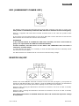


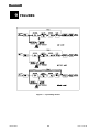
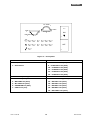


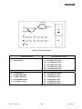
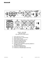


![Evo 6-15 TM USER MANUAL_vers. 4.0_[EPO CHIUSO]](http://vs1.manualzilla.com/store/data/006156965_1-3c2ff8a96ef48085f557a3503c0c4135-150x150.png)

![[ITA] ERA LCD 1.5 - 2.0 - 2.6 v.3.0](http://vs1.manualzilla.com/store/data/006158360_1-723f61f8946d2d729252a86ec11afdef-150x150.png)
![[ENG] EVO DSP TM 10-30 kVA User Manual v. 2.0](http://vs1.manualzilla.com/store/data/005715238_1-26b73917878f712f842422018d03a475-150x150.png)