1
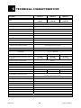
EVO
Uninterruptible Power Supply
EVO 1.0
EVO 2.0
EVO 3.0
USER’S MANUAL
11
INDEX
SECURITY NOTICE
page
2
INTRODUCTION
page
3
UPS EVO
1
MAIN CHARACTERISTICS
page
4
2
EXTERNAL DESCRIPTION
page
5
page
8
FRONT PANEL
REAR SIDE
3
RUNNING OPERATIONS
SWITCHING ON
LINE MODE
BATTERY MODE
LOW BATTERY AND AUTOMATIC RESTART
LOAD TEST
4
INSTALLATION INSTRUCTIONS
page 11
RECEIPT OF UPS
PLACEMENT
FIRST START UP
5
COMPUTER INTERFACE
page 12
6
TECHNICAL CHARACTERISTICS
page 13
7
SUGGESTIONS FOR A CORRECT USE
page 14
MAINTENANCE
BATTERY MAINTENANCE
SAFETY FOR THE OPERATOR
8
ANOMALIES AND TROUBLESHOOTING
page 15
9
FIGURES
page 17
© Copyright 2006
TECNOWARE s.r.l. All rights reserved.
All trademark are property of their respective owners.
TECNOWARE s.r.l.
www.service.tecnoware.com
This manual has been printed and edited by TECNOWARE s.r.l.
November 2006 Edition version 3.0
User’s manual
1
UPS EVO
11 SECURITY NOTICE
Read this manual carefully before installing and using TECNOWARE EVO
Uninterruptible Power Supply, which will be referred to as UPS from
hereafter.
The UPS must be used only by properly trained personnel. To ensure correct
and safe operation, it is necessary that operators and maintenance
personnel observe the general Safety Standards as well as the specific
instructions included in this manual.
Risk of electric shock: do not remove the cover. The UPS contains internal
parts which are at a high voltage and are potentially dangerous, capable of
causing injury or death by electric shock.
There are no internal parts in the UPS that can be repaired by the user. Any
repair or maintenance must be performed exclusively by qualified technical
personnel authorized by TECNOWARE.
TECNOWARE declines any responsibility if this warning is disregarded.
It is compulsory to ground the UPS according to Safety Standards.
Risk of electric shock at the output socket when the UPS is ON.
Risk of electric shock at the output socket while the unit is connected to the
AC utility line.
Use the input power cable given with the unit and connect it to the AC utility
line. In all circumstances a (H05VVF3G 1,5mm²) cable or a better one must
be used.
Do not obstruct ventilation slots or holes and do not place any object on top
of UPS.
Do not insert objects or pour liquids in the ventilation holes.
Do not keep liquids, flammable gases or corrosive substances near the UPS.
Install the UPS
environment.
UPS EVO
indoors,
in
a
protected,
2
clean
and
moisture-free
User’s manual
11
INTRODUCTION
UPS EVO
UPS EVO (Uninterruptible Power Supplies) are the result of constant technological research
aimed at obtaining the best performance at the lowest cost.
UPS EVO are advanced ON-LINE UPS, single-phase, built specifically to protect your computer
from any irregularities in the AC line (for example blackouts, brownouts, overvoltages, microinterruptions) which often cause damage to hardware and software.
During a power failure, EVO continues supplying adequate AC power (with a true sinewave) to
all connected devices by its internal battery and by its DC/AC converter (Inverter).
Under normal AC line condition, EVO provides an automatic output voltage regulation by the
Rectifier and Inverter blocks and filters out frequently occurring electrical disturbances (high
voltage transients, spikes, interferences, etc.), thus protecting the devices connected to its
outlets.
EVO protects the devices from accidental overload or Inverter fault by an AUTOMATIC BYPASS
that directly connects the AC input line with its outlets.
EVO is supplied with an RS-232 communication port and USB port, which can be used to signal
to a generic processor or computer the absence of mains condition or the end of autonomy
condition. This permits to carry out an automatic data saving operation during a long black out
with the most spread Operating Systems (Windows, Linux, Novell, etc).
Furthermore, the communication ports permit EVO to communicate with the computer,
transferring various measurements such as: input output voltage, battery voltage, output
power, frequency, and can also be programmed for automatic operations such as switching
ON/OFF in a preset time.
WARNING
Please read this manual before using EVO, because it contains important safety
information for the operator in order to carry out a correct use of the unit.
This manual is related to the below EVO models:
•
EV0 1.0
•
EV0 2.0
•
EV0 3.0
In this manual, the same for all 3 models, EVO will simply be called UPS.
EVO is constantly being developed and improved: consequently, your unit may differ somewhat
from the description contained in this manual.
User’s manual
3
UPS EVO
11
MAIN CHARACTERISTICS
EVO offers all the modern characteristics which guarantee maximum reliability and security:
•
Microprocessor control guarantees high reliability
•
ON-LINE double technology without transformer
•
Pure Sinewave
•
Output voltage regulation +/- 2%
•
Overload, overheating and short circuit protection
•
AUTOMATIC BYPASS to protect from accidental overload or Inverter fault
•
MANUAL BYPASS through switch on the rear side
•
Switching ON even with no mains condition
•
Automatic protection in case of discharged batteries
•
After a shutdown caused by the end of autonomy and when mains condition is restored there
is an automatic SWITCHING On operation
•
Automatic functioning test through a switch
•
Automatic regulation to the input frequency 50 or 60 Hz
•
Visual warnings by leds, indicating operational mode and low battery, overload and alarm
conditions
•
Dry contact board (optional)
•
SNMP Adapter (optional)
•
EPO (Emergency Power OFF)
•
Remote ON/OFF
•
Acoustic signals of various kinds indicating alarm situations
•
Communication with the computer by a RS-232 Interface and possible monitoring of
input/output voltage, frequency, output power, battery voltage, etc.
•
Automatic turn on/off user-programmable by RS-232 Interface
•
Protection filter for the telephone, ADSL and data line
•
Possibility to increase the autonomy through External Battery boxes (optional)
•
High reliability and high performances
•
Easy to use
UPS EVO
4
User’s manual
12
EXTERNAL DESCRIPTION
FRONT PANEL
On the front panel there are the control buttons and some leds which indicate the various
operating mode and alarm conditions. Please see the figures 1 and 2
OFF button
To turn off the UPS, press this button for more than one second.
ON/TEST/ALARM button
Can be used for 3 functions:
•
TURN ON: the UPS is turned on by keeping the button continuously pressed for more than 1
second.
•
SELF-TEST: the UPS performs a SELF-TEST, according to the procedure explained further on,
when the button is pressed during LINE mode for more than 1 second.
•
ALARM OFF: during BATTERY mode, to disable the alarm buzzer, press this button for more
than 1 second.
LINE led
This led (blue) is ON when the input AC line voltage amplitude is within the specification, and it
indicates the UPS is working in LINE mode.
If LINE led flashes every second it shows that Phase line and Neutral line of AC input utility line
are inverted. In that case it must disconnected the AC power input plug from power receptacle,
turn it at 180 degrees and plug in the power receptacle again
INVERTER led
This led (blue) is on when the Inverter is regularly working
BATTERY led
This led (blue) is on when the UPS is working in BATTERY mode (during a blackout or
overvoltage/brownout).
BYPASS led
This led (blue) is on when the UPS is working in BYPASS mode: the AC input line is connected
directly with the UPS outlets.
FAULT led
This led (red) is turned on whenever the UPS detects a FAULT condition and needs a technical
intervention as soon as possible.
User’s manual
5
UPS EVO
LOAD LEVEL led bar
Refer figure 2 – Front Panel.
The led bar has 6 leds (5 leds are blue and one led is red). This bar indicates the output power
percentage (LOAD LEVEL), proportional to the number of switched on leds.
The greater the load the more LED indicators will light on.
There are the following LOAD LEVEL percentages:
•
•
•
•
•
0~20%: only one led is on (led13)
21~40%: two leds are on (led13 and led12)
41~60%: three leds are on (led13, 12 and 11)
61~80%: four leds are on (led13, 12, 11 and 10)
81~100%: five leds are on (led13, 12, 11, 10 and 9)
The OVERLOAD red led (led8), is on to warn of an OVERLOAD condition.
BAT. LEVEL led bar
Refer figure 2 – Front Panel.
The led bar has 6 leds (5 leds are blue and one is yellow). This bar indicates the battery
capacity percentage (BAT. LEVEL), proportional to the number of switched on leds.
The higher the battery capacity the more LED indicators will light on.
There are the following battery capacity percentages:
•
•
•
•
•
100~81%: five leds are on (led15, 16, 17, 18 and 19)
80~61%: four leds are on (led15, 16, 17 and 18)
60~41%: three leds are on (led15, 16 and 17)
40~21%: two leds are on (led15 and led16)
20~0%: only one led is on (led15)
The LOW BAT yellow led (led14), is on to warn of a LOW BATTERY condition during BATTERY
mode.
REAR SIDE
The following are located on the rear side (see figure 3):
1)
Grounded AC Input power socket: to connect the UPS to AC utility line by the supplied
input cord.
2)
Input Circuit Breaker: it goes off in overload or short-circuit condition; push the external
3)
Grounded output socket: for connecting equipments to be protected.
4)
(Only EVO 2.0 and EVO 3.0) Grounded power output socket: for connecting an
output power line to supply all the equipments to be protected.
5)
RS-232 Computer Interface (female connector 9 poles DB9): it is the interface port
(RS-232) to communicate with a computer.
6)
RJ11/RJ45 IN/OUT plugs: to protect and filter a phone line, an ADSL or a LAN.
7)
Slot for external batteries connector: to connect the UPS to an external Box Battery
(optional).
8)
Dry contact board / Slot for SNMP adapter (optional).
9)
Manual BYPASS switch: to force the UPS into BYPASS mode (see chapter “Running
Operations”).
10) Remote ON/OFF contact.
11) EPO (Emergency Power OFF).
UPS EVO
6
User’s manual
EPO (EMERGENCY POWER OFF)
EPO
2
1
Remote Button
EPO
The EVO models have the EPO (Emergency Power OFF) connector (2 terminals connector) on
the rear. This permits to immediately switch the UPS OFF from a distance in case of emergency.
To use EPO function is very simple: it is sufficient to connect an external switch to the EPO
terminal(see Figure 3 – Rear Side): if the switch is CLOSED the UPS works normally. If on the
contrary, the switch is OPEN then the UPS turns OFF immediately. To switch ON the UPS again
it is necessary to close the EPO switch and then manually restart the UPS from the front panel.
The EPO terminals are isolated and do not need an external feeding voltage.
REMOTE ON/OFF
ON
1
OFF
2
3
4
Remote Button OFF
Remote Button ON
The EVO models have remote ON/OFF terminals connector on the rear side (see figure 3),
this permits to switch the UPS ON and OFF from a distance. Using the ON/OFF external
button (as described in the above picture) the frontal panel button capacity can be used
from a distance.
Evo is on; pressing the OFF button connected to terminal 1 and 2 for at least 3 seconds,
EVO turns OFF.
EVO is off; pressing the ON button connected to terminal 4 and 5 for at least 3 seconds,
EVO turns ON.
The remote ON function is disabled when the UPS is off and the AC input line voltage is not
present.
User’s manual
7
UPS EVO
DRY CONTACTS BOARD (OPTIONAL)
Fault
Common
1
2
3
4
Bypass
6
5
AC fail
7
8
Low BAT
9
10
The Dry Contact board has a 10 pin connector on the rear side of the UPS.
1. Common
Pin 1 and Pin 2 are common pins.
2. Fault
Pin 3 is the normal-open output: When UPS works normally, Pin 3 and Pin 1-2 will be open,
when UPS is failed, Pin 3 and Pin 1-2 will be closed.
Pin 4 is normal-closed output: When UPS works normally, Pin 4 and Pin 1-2 will be closed,
when is failed, Pin 4 and Pin 1-2 will be open.
3. Bypass
Pin 5 is the normal-open output: When UPS works normally, Pin 5 and Pin 1-2 will be open,
when UPS works in bypass mode, Pin 5 and Pin 1-2 will be closed.
Pin 6 is normal-closed output: When UPS works normally, Pin 6 and Pin 1-2 will be closed,
when UPS works in bypass mode, Pin 6 and Pin 1-2 will be open.
4. AC fail
Pin 7 is the normal-open output: When UPS works normally, Pin 7 and Pin 1-2 will be open,
when UPS works in AC failure mode, Pin 7 and Pin 1-2 will be closed.
Pin 8 is normal-closed output: When UPS works normally, Pin 8 and Pin 1-2 will be closed,
when UPS works in AC failure mode, Pin 8 and Pin 1-2 will be open.
5. Low Bat
Pin 9 is the normal-open output: When UPS works normally, Pin 9 and Pin 1-2 will be open,
when UPS works in battery low voltage mode, Pin 9 and Pin 1-2 will be closed.
Pin 10 is normal-closed output: When UPS works normally, Pin 10 and Pin 1-2 will be
closed, when UPS works in battery low voltage mode, Pin 10 and Pin 1-2 will be open.
The Dry Contact board is OPTIONAL
UPS EVO
8
User’s manual
13
RUNNING OPERATIONS
SWITCHING ON
If the UPS is switched off and connected to the electric line, the LINE Led in the front side is
switched on together with the BAT. LEVEL led bar showing batteries capacity level. In these
conditions UPS has the only function of recharging batteries and there is no power on the output
sockets (switched off output). If it is disconnected from the AC utility line, after some second
UPS is switched off completely.
The UPS is switched off and connected to the AC utility line (LINE Led and BAT. LEVEL bar are
switched on). In order to switch the UPS on, it is sufficient to press continuously for more than
1 second ON/TEST/ALARM button of the front panel till when the UPS emits a short acoustic
signal showing its own switching on. The UPS effectuates an initial operating SELF TEST (during
which the red FAULT and OVERLOAD leds are switched on), and then activates the power on the
output sockets and at the same time it switches on the BYPASS led and the LOAD LEVEL bar
(indicating output power percentage); it starts working in BYPASS mode. After some second the
BYPASS led is switched off and the INVERTER Led is switched on: all this indicates that UPS has
started working normally in LINE mode.
If the UPS is not connected to the AC utility line or if the AC utility line is not present due to a
blackout, the UPS turns on with a sequence similar to the one described above.
Even in this case it needs to press continuously for more than 1 second ON/TEST/ALARM
button, till when the UPS emits a short acoustic signal showing its own switching on. The UPS
immediately switches on BAT. LEVEL bar, then it effectuates an initial operating SELF TEST
(during which the red FAULT and OVERLOAD leds are switched on), it switches on BATTERY Led
and after some seconds it activates the power on the output sockets and at the same time it
switches on INVERTER led and LOAD LEVEL bar (indicating output power percentage); it starts
working normally in BATTERY mode.
The UPS automatically returns to function in LINE mode a few seconds after the AC utility line is
recovered.
To switch the UPS off, press the OFF button for more than 1 second, till when the UPS emits a
short acoustic signal showing its own switching off. The output is disabled and all devices
powered by the UPS are switched off. The INVERTER led is switched off and UPS effectuates
then an operating SELF TEST (during which the red FAULT and OVERLOAD leds are switched
on).
If UPS is connected to the AC utility line, LINE led and BAT. LEVEL led bar remain switched on.
In these conditions, UPS effectuates only batteries recharging function and there is no power on
the output sockets (switched off output).
If UPS is not connected with the AD utility line, after some seconds it is switched off completely.
LINE MODE
This is the typical running mode: the AC input line is present and the amplitude is within
specifications. The UPS filters the input line, performs an output voltage regulation by the
RECTIFIER, BOOSTER and INVERTER blocks and supplies power to all connected devices.
Besides, it recharges the batteries and keeps them in an ideal charge condition.
The LINE mode is characterized by:
•
The LINE led and INVERTER led switched on.
•
The LOAD LEVEL and BAT. LEVEL led bars switched on.
User’s manual
9
UPS EVO
BATTERY MODE
The UPS automatically runs in BATTERY mode if the Mains Voltage amplitude gets out of
security limits (in case of a black-out or overvoltage-lowvoltage): in this case, the UPS supplies
the required output power by its internal battery and by the DC/DC CONVERTER, BOOSTER and
INVERTER blocks (see figure 1).
The UPS automatically returns to function in LINE mode a few seconds after the AC input line is
recovered.
The BATTERY mode is characterized by:
•
An acoustic signal every 4 seconds indicates that the batteries are discharged. The acoustic
signal can be disconnected by pressing the ON/TEST/ALARM button.
•
The INVERTER led and BATTERY led switched ON.
•
The LOAD LEVEL and BAT. LEVEL led bars switched on.
BYPASS MODE
In BYPASS mode (see figure 1), the AC input line is directly connected with the UPS outlets by
an AUTOMATIC BYPASS.
EVO uses the BYPASS mode during the start-up phase; furthermore the UPS switches
automatically to BYPASS mode in consequence of accidental overload or Inverter fault thus
protecting the supplied devices.
The BYPASS mode is characterized by:
•
The BYPASS led and LINE led switched on.
•
The LOAD LEVEL and BAT. LEVEL led bars switched on.
The UPS can be transferred in BYPASS mode even through a manual operation.
First of all it must be sure that the UPS is working properly in LINE mode. On the rear side of
the product (see figure 3) it is positioned the manual BYPASS switch. If this switch is in
position ON (BYPASS), the UPS changes in BYPASS mode and indicates this condition with:
•
The BYPASS led and LINE led switched on.
•
All the LOAD LEVEL led bar switched on, the red OVERLOAD and FAULT Leds switched on.
•
Continuous acoustic alarm.
The UPS starts working again normally if it moves the switch in OFF (NORMAL) position.
Acoustic alarm stops immediately and the UPS effectuates then an operating SELF TEST (during
which the red FAULT and OVERLOAD Leds are switched on). After some seconds more the
BYPASS led is switched off and the INVERTER led is switched on: this indicates that the UPS has
started working normally in LINE mode.
During the above mentioned operations, the devices powered by UPS will continue working
regularly
WARNING
BYPASS operations must be carried out ONLY by qualified Technical personnel
specialised and authorised by Tecnoware.
UPS EVO
10
User’s manual
LOW BATTERY AND AUTOMATIC RESTART
In BATTERY mode, EVO indicates the LOW BATTERY condition whenever the battery reaches a
charge level allowing connected devices to operate for approximately one more minute.
The UPS warns the user of this LOW BATTERY condition by increasing the acoustic alarm signal
(there is an acoustic signal every second) and by turning on the yellow led of the BAT. LEVEL.
If the AC utility power is not restored within one minute of this condition, the UPS will
automatically switch OFF. This will protect the batteries from a sudden deep discharge. EVO
stops supplying output power, will deactivate the alarm signals and will place itself in a stand-by
mode. When the AC utility power is restored, the UPS automatically switches ON and
returns to work in LINE mode.
After a complete discharge the UPS will need around 8 hours to completely recharge the
batteries. The recharge is automatic in either two ways:
•
The UPS is ON and running in LINE MODE
•
The UPS is OFF and connected to an AC input line
LOAD TEST
EVO indicates the output power percentage by the LOAD LEVEL bar. The output power is
proportional to the number of the leds switched on as described into the chapter “External
description”.
The UPS warns of an OVERLOAD condition by lighting up the red OVERLOAD led at the top of
the LOAD LEVEL bar.
In LINE mode, EVO has the capability to accept an overload from 110% to 150% for about 30
seconds (the UPS indicated the OVERLOAD condition by lighting up the red OVERLOAD led and
by an acoustic signal every second) and after it switches automatically to the BYPASS MODE.
In LINE mode, EVO switches automatically to the BYPASS mode as soon as the overload is
higher than 150%.
Once the requested power is back within range, EVO switches automatically to the LINE mode
again.
In BATTERY mode, EVO has the capability to accept an overload from 110% to 150% for about
30 seconds (the UPS indicated the OVERLOAD condition by lighting up the red OVERLOAD led
and by an acoustic signal every second) and after it turns automatically off.
In BATTERY mode, EVO switches automatically off as soon as the overload is higher than 150%.
After removing the cause for the overload condition in order to switch the UPS ON again it is
necessary to press the OFF button in order to switch the UPS OFF. Wait for a few seconds and
then press the ON/TEST/ALARM button.
It is possible to carry out a LOAD TEST in the following way:
•
•
Make sure that UPS is working in LINE mode, with all powered equipment switched ON and
absorbing MAXIMUM POWER.
Press the ON/TEST/ALARM button for more than 1 second, to start the TEST.
EVO begins operating in BATTERY mode. The TEST is overcome if all equipments keep on
working and if the UPS does not signal any anomalies (overload or other). After a few seconds
the TEST is finished and the UPS returns in LINE mode.
We advise you to carry out the LOAD TEST periodically in order to check the UPS
efficiency.
WARNING
Make sure that the UPS never indicates OVERLOAD when running.
Do not connect a load greater than the rated nominal value on the UPS label (see
POWER specifications in the TECHNICAL CHARACTERISTICS chapter), as this may
damage the unit. In this case the warranty is void.
User’s manual
11
UPS EVO
14 INSTALLATION INSTRUCTIONS
RECEIPT OF UPS
Inspect the UPS upon receipt. If the UPS has been damaged during shipment, keep the box and
packing material for the carrier. Notify the carrier and dealer immediately. Make sure the
following is in the box
•
EVO UPS
•
UPS output cable
•
AC input power cord
•
Phone cable
•
User’s manual
•
UPSILON 2000 software for UPS management (including CD-rom and RS-232 cable)
•
User’s manual
We advise you to keep the original box in a safe place and use it in case the UPS needs to be
sent to the service for maintenance.
PLACEMENT
We advise you to place the EVO as close as possible to the AC input line and to the equipment
that needs to be powered. The UPS is designed to operate in protected environments (for
example: offices).
This UPS should be installed indoors with adequate airflow and free of contamination. Locate it
in a clean and indoor environment, free from moisture, flammable liquids, and direct sunlight.
In all circumstances, see the TECHNICAL CHARACTERISTICS chapter for environmental
specifications and check that the selected area meets these criteria.
EVO requires at least 20 cm of unobstructed space all around in order to be properly ventilated.
Do not obstruct ventilation holes and do not insert objects or liquids in the ventilation holes.
Do not place any object on top of the EVO UPS. Do not pour liquids, flammable gases, or
corrosive substances near or on the unit.
UPS EVO
12
User’s manual
FIRST START-UP
The first start-up procedure is very simple. We advise you to follow the steps below explained.
1.
2.
Through the supplied cable connect the UPS to the AC line outlet. It is mandatory to
ground the outlet according to the Safety Standards. Carefully check the grounding,
make sure that the utility power is available, and that its range falls within the UPS
specifications.
Switch the UPS ON and see that it operates correctly. Check that the UPS does not signal
any sort of anomaly. Wait for the correct switching to LINE mode and make sure that the
cooling fans are set in motion. Leave the UPS in LINE mode for at least 8 hours in order to
completely recharge the batteries.
3.
Switch the UPS OFF.
4.
Connect the devices to be supplied to the UPS output sockets. Then put all the
main switch of each device in the ON position.
5.
Restart the UPS; and see that it operates correctly; wait for the UPS to start working
properly in LINE mode and that no overload signal or any other form of anomalies are
present. Then make sure that all equipments switch on correctly.
In case of Overload immediately reduce the power demand by disconnecting the devices
that cause the overload. Switch OFF the UPS and repeat point 4 and 5.
6.
Carry out the LOAD TEST according the modalities described in charter LOAD CONTROL.
Carry out step 3, 4, 5, 6, of the initial start up procedure to change the configuration of the
devices protected by the UPS.
WARNING
It is compulsory to ground the UPS according to safety Standards.
Risk of electric shock: do not remove the cover. The UPS contains internal parts
which are at a high voltage and are potentially dangerous, capable of causing injury
or death by electric shock.
There are no internal parts in the UPS which are user serviceable. Any repair or
maintenance work must be performed exclusively by qualified technical personnel
authorized by TECNOWARE. TECNOWARE declines any responsibility if this warning
is disregarded.
Risk of electric shock at the output socket if the UPS is ON, even when the UPS is not
connected to AC utility line.
Risk of electric shock at the output socket while the unit is connected to AC utility
line.
Disregard for these warnings may lead to a risk of electric shock to operators.
15
COMPUTER INTERFACE
EVO is gifted with an RS-232 interface which can be used as a communication port with a
computer.
A 9 poles female connector (DB9) is fitted on the rear side.
On the DB9 connector the following RS-232 signals are present:
•
RX (pin 2)
•
TX (pin 3)
•
GND (pin 5 and pin 7)
The RS-232 interface signals are isolated through photo-couplers.
User’s manual
13
UPS EVO
16
TECHNICAL CHARACTERISTICS
EVO MODEL
EVO 1.0
EVO 2.0
EVO 3.0
POWER
1000 VA
(700 W)
2000 VA
(1400 W)
3000 VA
(2100 W)
NOMINAL INPUT VOLTAGE
Single Phase 220/230 V
INPUT VOLTAGE RANGE
+ 20 % / -25 %
INPUT/OUTPUT FREQUENCY
50 / 60 Hz (automatic selection)
± 5%
INPUT FREQUENCY RANGE
NOMINAL OUTPUT VOLTAGE
Single Phase 220/230 V
± 2%
OUTPUT VOLTAGE REGULATION
INVERTER WAVEFORM
Sinewave
< 3%
THD (TOTAL HARMONIC DISTORSION)
OVERLOAD CAPABILITY
< 150% for 30 seconds; > 150% for 10 cycles
TYPICAL TRANSFER TIME
0 ms (ON-LINE)
Uninterrupted transfer of 100% load from
UPS to Bypass and vice versa
AUTOMATIC AND MANUAL BYPASS
CERTIFICATIONS
CE
8 – 15 minuts
AUTONOMY
NOMINAL BATTERY VOLTAGE
SEALED MAINTENANCE FREE LEAD ACID
BATTERIES
36
96
96
3 units
12V 7,2Ah
8 units
12V 7,2Ah
8 units
12V 7,2Ah
TYPICAL BATTERY CHARGE TIME
8 Hours
EXPANDABLE AUTONOMY
Optional
AUDIBLE NOISE (at 1 metre)
< 45 dBA
COOLING
Fan cooling
WEIGHT
DIMENSIONS (L x H x P)
ENVIRONMENTAL SPECIFICATIONS
13
33
34
15 x 21 x 41
19 x 34 x 47
19 x 34 x 47
Temperature 0-40 °C
Humidity 0-95% with no condensation
Maximum Height 3000 metres
COMPUTER INTERFACE
UPS MANAGEMENT SOFTWARE
1 RS-232 port
Included UPSILON 2000 software with RS232 cable
SNMP INTERFACE
Optional
EPO (EMERGENCY POWER OFF)
Included
REMOTE ON/OFF
Included
DRY CONTACTS BOARD
Optional
FILTERED PHONE PLUG
Plug RJ11/RJ45 included
WARRANTY
2 years
Technical data may change without prior notice
UPS EVO
14
User’s manual
17
SUGGESTIONS FOR A CORRECT USE
MAINTENANCE
EVO needs minimal maintenance throughout its lifetime.
WARNING
Prior to achieve any check up or cleaning operations make sure that the UPS is
switched off and that the mains voltage in the UPS input is switched off.
We advise to periodically check the mains input cable, the output connections and to dust the
ventilation holes.
Do not use liquids or detergents to clean the UPS. Only use a humid cloth.
Before switching the EVO on make sure that it is perfectly dry.
If accidentally some liquid penetrates inside the UPS, do not switch the UPS on and immediately
consult authorised Technical Service.
BATTERY MAINTENANCE
The battery recharge is automatic when the UPS is ON and working in LINE mode. The
batteries are also recharged if the UPS is OFF and connected to the mains.
It is necessary to carry out a three-monthly functioning test in BATTERY mode, this will
preserve the batteries in an excellent state and extend the life duration.
Leave the UPS in BATTERY mode until the end of autonomy condition is reached. After which
restore the input mains. The UPS will return functioning in LINE mode and will fully recharge the
batteries in around 8 hours.
If the UPS is left unused, and disconnected from the mains, it is advised to recharge the
batteries at least once in a month for around 8 hours.
After a period of inactivity, we advise to carry out the INITIAL START UP procedure described in
this manual, before using the UPS.
Carefully follow the rules related to the battery maintenance. Otherwise warranty can
be declined.
SAFETY FOR THE OPERATOR
If the EVO does not have the original security characteristics, it must be made non functional,
and a non authorised use must be avoided.
The problem must then be reported to qualified technical personnel.
The original security characteristics can be lost if for example the EVO shows visible damages or
an anomalous running.
User’s manual
15
UPS EVO
18
ANOMALIES AND TROUBLESHOOTING
A list of anomalies and related solutions are described below:
The UPS does not switch on and does not give any signals
•
Press the ON/TEST/ALARM button on the front panel for more 1 second. If the UPS does
not switch on go into the next step.
•
Leave the UPS connected to the mains for at least 4 hours in order to recharge the batteries.
Then try to switch on again.
The UPS continues to run in BATTERY mode and the mains input
voltage is present.
•
Make sure that the UPS input voltage is present and that the voltage amplitude is within the
internal specifications.
•
Before you go on to the next operations switch the UPS OFF and remove the UPS
input voltage.
•
Check the Input Circuit Breaker. Should it be snapped (OFF position) check if the UPS is
overloaded; then try to rearm the breaker by bringing it in the ON position (keep it pressed)
•
Check the feeding cable and all connections.
Equipments connected to the UPS do not switch ON
•
Before you go on to the next operations switch the UPS OFF and remove the UPS
input voltage.
•
Check the condition of every feeding cables and their right connection.
The UPS indicates OVERLOAD
•
Check which dispositives are feeding by the UPS and if it is really overloaded.
•
Bring the power request within the specifications and disconnect the dispositives that cause
the overload.
The UPS autonomy is lower than the specified one.
•
UPS EVO
Recharge the batteries for at least 8 hours and then check the autonomy again.
16
User’s manual
WARNING
Risk of electric shock: do not remove the cover. The UPS contains internal parts
which are at a high voltage and are potentially dangerous, capable of causing injury
or death by electric shock.
There are no internal parts in the UPS which are user serviceable. Any repair or
maintenance work must be performed exclusively by qualified technical personnel
authorized by TECNOWARE.
TECNOWARE declines any responsibility if this warning is disregarded.
If the described anomalies should continue despite the advised
troubleshooting, or should they manifest in any other form, please
contact:
TECNOWARE SERVICE
www.service.tecnoware.com
User’s manual
17
UPS EVO
19
FIGURES
Figure 1 – Operating modes
UPS EVO
18
User’s manual
BY-PASS 5
TEST
LOAD
LINE
INVERTER
3
ON
6
BATTERY
4
1
+ 14
15
16
17
18
19
8
9
10
11
12
13
OFF
2
7
Figure 2 – Front panel
Front buttons
LOAD level led bar
1 - ON/TEST/ALARM Button
8 – OVERLOAD led (red)
2 – OFF Button
9 - LOAD 100% led (blue)
10 - LOAD 80% led (blue)
11 - LOAD 60% led (blue)
12 - LOAD 40% led (blue)
13 - LOAD 20% led (blue)
Operating modes leds
BAT. level led bar
3 – LINE led (blue)
14 - LOW BAT led (yellow)
4 – BATTERY led (blue)
15 - BAT 20% led (blue)
5 – BYPASS led (blue)
16 - BAT 40% led (blue)
6 – INVERTER led (blue)
17 - BAT 60% led (blue)
7 – FAULT led (red)
18 - BAT 80% led (blue)
19 - BAT 100% led (blue)
User’s manual
19
UPS EVO
Figure 3 – Rear side
(On the left: EVO 1.0; on the right: EVO 2.0 and EVO 3.0)
UPS EVO
1.
Grounded AC Input socket
2.
Input Circuit Breaker
3.
Grounded output socket
4.
Grounded power output socket (EVO 2.0 and EVO 3.0)
5.
Computer Interface (RS-232)
6.
RJ11/RJ45 IN/OUT plugs
7.
Slot for external batteries connector.
8.
Dty contacts board/Slot for SNMP adapter
9.
Manual BYPASS switch
10.
Remote ON/OFF contacts
11.
EPO (Emergency Power OFF)
20
User’s manual
24 MONTHS WARRANTY – valid in all UE countries
TECNOWARE S.r.l. guarantees the product for a period of 24 months from the original date of
purchase.
The date of purchase is proved with the receipt of account released by the authorised reseller,
which clearly indicates the date in which the product was sold and the product identification
code (model and serial number). Upon request of Technical assistance, a copy of your receipt
must be surrendered.
This guarantee implies free reparation or free substitution of any products parts or components
which result faulty due to defective manufacture. In such case the transportation costs are
covered by the guarantee service.
In the event of irreparable fault, or should the same malfunction repeat itself, TECNOWARE
S.r.l will provide the final decision on the product substitution.
Any parts damaged due to the negligence or carelessness in using the product (such as failing
to follow the correct operating instructions indicated in the user manual), violations, incorrect
installation or maintenance operated by non authorized personnel, transportation damages,
natural calamities, accidental causes, phenomenon not subordinated to the normal product
functioning, non qualification of environment in which the product operates, and in any case:
any circumstances in which one cannot date back to the defective manufacture, will not be
covered by the guarantee
Compensation is excluded for: direct or in direct damages of any nature caused to people or
objects, by the incorrect use of product; by the discontinuance of product functioning, or for
stopping the usage due to the product servicing.
This guarantee is valid upon the terms and conditions cited above, in all the countries belonging
to the UE countries.
CONFORMITY TO THE EUROPEAN DIRECTIVES
TECNOWARE S.r.l. confirms that EVO models comply with the requirements set out in: the Low Voltage
Directive (Safety) 73/23/EEC and following amendments, the EMC (Electro-Magnetic Compatibility)
Directive 89/336/EEC and following amendments.
The following standards were applied:
Low Voltage Directive (Safety): EN62040-1-1: 2003
EMC Directive (Electro-Magnetic Compatibility): IEC62040-2: 2001, IEC61000-3-2: 2001, IEC61000-3-3:
2001, EN55022: 1998, IEC61000-6-4: 20011
PRODUCT DISPOSAL
EVO cannot be disposed as an urban waste, but must be treated as a separate
waste. Any violation is indictable with financial sanctions as per in force regulations.
An incorrect waste disposal or an improper use of the same or of any parts can be
damaging for the environment and for human health.
A correct waste disposal of products having the dustbin symbol marked by a cross
help to avoid negative consequences to the environment and to human health.
User’s manual
21
UPS EVO
TECNOWARE S.r.l.
www.service.tecnoware.com