1
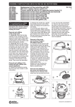
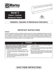
AWARNING
Risk of electric shock
- Do not use in wet locations.
- Use indoors only.
- Turn power off before servicing -- see instructions.
- Properly ground fixture.
- Ensure that no bare wires are exposed outside the electrical
connections.
Risk of injury
- Bulb may shatter and cause injury if broken.
- Do not use excessive force when installing bulb.
- Some metal parts in the fixture may have sharp edges. To prevent
cuts and scrapes, wear gloves when handling the parts.
- Account for small parts and destroy packing material, as these
may be hazardous to children.
Risk of burn
- Allow bulb to cool before handling.
Risk of fire
- Minimum 90° C supply conductors.
- Not intended for illumination of aquariums.
- Not intended for use above stoves, cook tops, or sinks.
- Not intended for recessed installation in ceilings or soffits.
- Not intended for surface installation inside or on top of built-in
furnishings such as kitchen cabinets, china cabinets, or trophy
OPERATION INSTRUCTIONS
1. The switch for this fixture is activated by the pull chain. Pull the chain
firmly and hold until the light comes on, then release the chain slowly to
prevent the chain from recoiling. Repeat the process to turn the light off.
2. A longer string is provided as an extension to the pull chain, if needed.
INSTALLATION PROCEDURES
1. Consult a local licensed electrician or electrical contractor if you are not sure about the
installation.
2. Ensure that electricity is TURNED OFF at the main circuit breaker or fuse box. DO NOT
ATTEMPT TO INSTALL FIXTURE WITH THE POWER ON.
3. Select a suitable dry mounting location (for indoor use only). Make sure the mounting surface
is capable of supporting the fixture.
A. Remove the lens/diffuser by lightly pushing in the front edge slightly and pulling down. The
lens/diffuser should pop out easily. See Figure 1.
5. Remove the bulb by grasping the ends of the bulb and rotating until the bulb becomes loose.
Pufl straight out from the lamp holder and remove any cardboard inserts present. Be careful
not to drop the bulb. See Figure 1.
6. Remove the cover/housing by unscrewing the nuts located behind the bulb and also the
screws located on the cover/housing surface with the pull chain. Slide the housing forward
before lifting. The hardware kit is inside the wiring cavity. If the center wiring hole on the
back of the fixture is going to be used (See Figure 6), install the provided bushing and skip to
instaliation procedure 10.
7. Choose a suitable knock-out location from those provided on the fixture. Remove the
knock-out with a screw driver. See Figure 5. The installation kit includes a "mini" 3/8" trade
size strain relief. It is to be used for the smaller |13rnrn) knock out holes only. If the larger 7/8"
(22.2mm) knock out holes are to be used, then a standard 3/8" trade size strain relief (not
included), should be used.
8. Insert the threaded end of the strain relief into the selected opening on the fixture. Secure the
strain relief by tightening the lock nut. The lock nut should be tightened with a toot such as a
pair of pliers to ensure the strain relief is properly grounded to the fixture.
9. Install the conduit or armored cable to meet electrical codes. Tighten the two screws on the
strain relief connector to secure the wires.
10. Connect the hot (black) AC supply wire(s) to the hot [black) wire(s) of the fixture. Secure the
connection with the wire nuts provided. See Figure 2.
11. Connect the white (neutral) AC supply wirels) to the neutral (white) wireis) of the fixture.
Secure the connection with the wire nuts provided. See Figure 2.
12. Connect the ground (green or copper) AC supply wire to the green or copper ground wire of
the fixture. Secure the connection with the wire nuts provided. If your electrical system
contains no grounding wire, you should consult a qualified electrician before proceeding
with the instaliation. See Figure 2.
13. Ensure that no bare wires are exposed after making the electrical connections.
BULB REPLACEMENT INSTRUCTIONS
See the label on the fixture for replacement bulb type information. Do not
replace with any other wattage of fluorescent bulb.
1) Turn the fixture off and allow bulb to cool before handling.
2) Remove the lens/diffuser by lightly pulling the rear edge towards the front
and down. The lens/diffuser should pop out easily. See Figure 1.
3) Remove the bulb by grasping the ends of the bulb and rotating until the
bulb becomes loose. Work the lamp pins out of the socket from the lamp
holder. Be careful not to drop the bulb. See Figure 1.
41 Grasp the replacement bulb in the same manner and reinsert into the
lamp socket and turn tube until it is securely held in place. Do not use
excessive force when installing bulb.
Lens/Diffuser (front edge)
Lente o difusor (parte frontal)
Figure 1
Figura 1
Nuts/Tuerca
Screw/Tornillo
Figure 2
Figura 2
If proceeding to junction box mounting instructions, skip installation procedure 14.
Strain Relief/
Prensacables
AC Supply Wires/
Cobles de alimentacion de CA
14. Arrange the wires inside the fixture and reattach the cover/housing. Ensure oil the wires and
connections are sealed properly inside the fixture without "pinching" any wires. Tighten the
screws and nuts.
Hot (Black) Supply Wire
Cable vivo (negro)
de alimentacion
JUNCTION BOX MOUNTING INSTRUCTIONS
1. The keyhole slots located on the bottom of the fixture are provided for mounting to the
following junction box types. See Figure 6:
. /t" x 4" square junction box • 4" octagon box • 2" x 4" handy box
2. Remove the 8/32" screws from the junction box and keep for later use.
3. Line up the chosen keyhole slots on the bottom of the fixture with the screw holes in the
junction box.
4. With the fixture in place, insert the 8/32" screw through the matching keyhole slots and into
the screw holes.
5. Tighten the screws, install cover/housing (refer to installation procedure 14), install bulb and
reinsert lens/diffuser.
6. Turn on the electricity at the circuit breaker or fuse box.
UNDER CABINET DIRECT WIRE MOUNTING INSTRUCTIONS
1. Place the fixture in the location where it is to be mounted and mark the position of the
keyholes with a pencil.
2. It is recommended that a pilot hole be drilled in the mounting surface for wood screws.
Pre-drill holes in the mounting surface with a 1/16" (1.5mm) drill bit for softwoods and a
3/32" (2.4mm) drill bit for hardwoods.
3. Drive the screws provided in the mounting hardware into the mounting
Figure
surface until approximately 1/8" (3.1mm) of space remains under the head
Figura
of the screw. See Figure 3.
4. Align the keyholes in the fixture with the two screws and slide into place.
See Figure 4.
5. Tighten the screws and install bulb and reinsert lens.
6. Turn on the electricity at the circuit breaker or fuse box.
This Jasco product comes with a 3 year limited warranty. Visit
www.jascoproducts.com for details.
Este producto de Jasco Products tiene una garantia limitada
de 3 Anos. Visite www.jascoproducts.com para detalles.
Ground (Green or
Copper) Wires
Cables dedescarga
a tierra [de cobre o
de color verde)
Neutral (White) Supply Wire
Coble neutro (bianco)
de alimentacion +
Hot (Black) Fixture Wire
->
Cable vivo (negro) de la unidad
Figure 3
Figura 3
6
6
Neutral [White) Fixture Wire
Cable neutro (bianco) de la unidad
Figure 4
Figura 4
Figure 5
Figura 5
AADVERTENCIA
Riesgo de descarga electrica
- No usar en lugares humedos.
- Usar en espacios interiores solamente.
- Desconectar la alimentation antes de la limpieza o la reparation: ver
- Recoger todas las piezas pequenas y destruir el material de embalajf
dado que estos pueden ser peligrosos para los ninos.
Riesgo de quemaduras
- Dejar que la bombilla se enfrie antes de manipularla.
instrucciones.
- Realizar la correspondiente conexion a tierra.
Riesgo de incendio
- Conductores de alimentation de 90° C como minima.
- No dejar cables desnudos expuestos porfuera de las conexiones
- No esta disenado para la iluminocion de acuarios.
- No esta disenada para usar sobre estufas, hornillas o fregaderos.
eiectricas.
Riesgo de lesiones
- Lo bombilla se puede romper en trozos pequenos y provocar lesiones.
- No aplicar demasiada fuerza al instalar la bombilla.
- Algunas partes metalicas de esto unidad pueden tener bordes fiiosos.
Para evitar cortes y raspaduras, use guantes al manipular las piezas.
PROCEDIMIENTOS DE INSTALACION
1. Si no esta seguro acerca de la instalacion, consulte con un electricista autorizado o
con un contratista electrico.
2. Asegurese de DESCONECTAR la eiectricidad en el disyuntor principo! o caja de
fusibles. NO INTENTE INSTALAR LA UNIDAD CON LA ALIMENTACION CONECTADA.
3. Seleccione un lugar adecuado y seco para el montaje (para uso en espacios
interiores solamente). Asegurese de que la superficie de montaje puede soportar la
unidad.
4. Retire la lente o difusor, de empujar iigeramente en el borde frontal [igeramente y
tirando hacia abdjo. La lente o difusor debe salir con facilidad. Vease la ftgura 1.
5. Saque la bombilla sujetdndola por sus extremos y haciendola girar hasta que se
afloje. Sdquela directamente desde el portalamparas y retire las inserciones de
carton que pueda haber. Tengo cuidado de no dejar caer la bombilla. Vease la
figura 1.
6. Quite la cubierta/vivienda por destornillando las tuercas situada detras de la
bombilla y tambien los tornillos ubicados sobre las viviendas de cubierta de
superficie con la cddena de extraction.Deslice la carcasa hacia delante antes de
levantarla. El kit de accesorios encuentra dentro de la cavidad de cableado. Si se
va a utilizer el agujero central de cableado en la parte posterior de la unidad (Vease
la figura 6), entonces, instale el buje que se incluye y pase al procedirniento de
instalacion 10.
7. Elija un lugar adecuado para los orificios prepunzonados de los que se ofrecen en la
unidad. Retire et orificio prepunzonado con un destornillador. Vease la figura 5. El
kit de instalacion incluye un prensacables de medida comerda! de "mini" 3/8 pulg.,
que se utilizara solamente para los orificios prepunzonados mas pequenos 113
mm}. Si se van a utilizer los orificios prepunzonados de mas grande 7/8 pulg. (22,2
mm), entonces se debe utilizar un prensacables de medida comerciol de estdndar
3/8 pulg. (no se incluye).
8. Inserte e! extreme roscado del prensacables en la abertura seleccionada de la
unidad. Asegure el prensacables, apretando la tuerca de seguridad. La tuerca de
seguridad se debe apretar con una herramienta como un par de pinzas paro
asegurar que el prensacables quede adecuadamente conectado a la unidad.
9. Instale el cable blindado segun los codigos electricos. Apriete los dos tornillos del
conector del prensacables para asegurar los cables.
10. Conecte el cable(s) vivo (negro) de CA a! cable(s) vivo (negro) de la unidad. Asegure
Id conexion con ias tuercas para cables que se induyea Vease la figura 2.
11. Conecte el cable(s) bianco (neutrol de CA al cable(s) neutro (bianco) de la unidad.
Asegure la conexion con las tuercas pdra cables que se incluyen. Vease la figura 2.
12. Conecte el cable de CA de conexion a tierra (de cobre o de color verde) al cable de
cobre o de color verde de conexion a tierra de Id unidad. Asegure la conexion con
las tuercas para cables que se incluyen. Si su sistema electrico no cuenta con
ningun cable de descarga a tierra, debe consultdr con un electricista calificado
antes de proceder con la instalacion. Vease la figura 2.
13. Asegurese de que no queden cables desnudos expuestos despues de hacer las
conexiones eiectricas.
- No esta disenada para instalaciones empotradas en cielos rasos o
techos falsos.
- No esta disenada para instalacion en superficie dentro o encima de
muebles empotrados, como gabinetes de cocina, gabinetes de
porcelana o vitrinas.
INSTRUCCIONES PARA EL MONTAJE DEL CABLE DEBAJO DEL GABINETE
1. Coloque la unidad en la ubicacion donde se va a montar y marque la position de los
orificios tipo bocallave con un lapiz.
2. Se recomienda que taladre un orificio piloto en la superficie de montaje para tornillos
de madera. Pretaladre orificios en Id superficie de montaje con una broca de 1/16
pulg. (1,5 mm) pdrd moderas blandas y con una broca de 3/32 pulg. (2,4 mm) para
maderas duras.
3. Coloque los tornillos que se incluyen en los accesorios de'montaje en !o superficie de
montaje hasta que quede un espado de aproximadamente 1/8 pulg. 13.1 mm)
debajo de la cabeza del tornillo. Vease la figura 3,
4. Alinee los orificios tipo bocallave de la unidad con los dos tornillos y deslicela hasta
que quede en su lugar. Vease la figura 4.
5. Apriete los tornillos e instale la bombilla y vuelva a inserter la lente.
6. Coioque la eiectricidad en el disyuntor o coja de fusibles.
INSTRUCCIONES DE OPERACION
1. El interrupter para este accesorio se activa por la cadena de extraction. Tire de ia
cadena firmernente y mantenga presionado hosta que la luz se endende y, a
continuadon, suelte la cadena lentamente para evitar que la cadena oscilantes.
Repita el proceso para apagar la luz.
2. Una cadena mas larga se proporciona como una extension a la cadena de
extraccion, si es necesario
INSTRUCCIONES PARA REEMPLAZAR LA BOMBILLA
Lea en lo etiqueta de la unidad la informacion sobre el tipo de bombilla para sustitudon.
No la sustituya con una bombilla fluorescente de diferente capacidad de vatios.
1. Apague la unidad y deje que se enfrie la bombilla antes de manipularla.
2. Retire la lente o difusor, halando Iigeramente el borde posterior hacia el frente y
hacia abajo. La lente o difusor debe salir con facilidad. Vease la figura 1.
3. Retire la bombilla, sujetdndola por los extremos y haciendola girar hasta que se afloje.
Saque los pasadores de la lampara del casquillo del portalamparas. Tenga cuidado
de no dejar caer la bombilla. Vease la figura 1.
4. Torne la bombilla de repuesto de la misma manera e insertela nuevamente en el
casquillo, haciendola girar hasta que quede bien asegurada en su lugar. No aplique
demasiada fuerza al instalar la bombilla.
If lamp is marked(Hg)it contains Mercury.
Follow local disposal laws. See WWW.LAMPRECYCLE.ORG
Si la lampara tiene la marca(Hg)contiene mercurio.
Siga las leyes locales de eliminacion. Ver WWW.LAMPRECYCLE.ORG
INCLUDED INSTALLATION ACCESSORIES
INCLUYE ACCESORIOS DE INSTALACION
Si precede con las instrucciones de montaje de la caja de conexiones, pase al
procedimiento de instalocion 14.
14. Organice los cables dentro de la unidad y coloque nuevamente la tapa o carcasa.
Asegurarse que todos los cables y las conexiones queden debidamente dentro de
la unidad sin "peilizcar" los cdbles. Apriete los tornillos y tuercas.
xl
INSTRUCCIONES PARA EL MONTAJE OE LA CAJA DE CONEXIONES
1. LOS siguientes tipos de cajas de conexiones se pueden montar en las ranuras tipo
bocallave que se encuentran en la parte inferior dela unidad. Vease la figura 6:
• Caja de conexiones cuadrada de 4 pulg. x 4 pulg. • caja de conexiones octagonal
de 4 pulg. • Caja pequeha de 2 pulg. x 4 pulg.
2. Retire los tornillos de 8/32 pulg. de la caja de conexiones y dejelos a un lado para su
uso posterior.
3. Alinee las ranuras tipo bocallave elegidas en la parte inferior de la unidad con los
agujeros para los tornillos de la caja de conexiones.
4. Inserte el tornillo de 8/32 pulg., con la unidad en su lugar, a troves de las ranuras
tipo bocallave correspondientes y en los orificios de los tornillos.
5. Apriete los tornillos, coloque la tapa o carcasa (consulte el procedimiento de
instaiacion 14) y coloque nuevamente la bombilla y la lente.
6. Endenda la eiectricidad en el disyuntor o caja de fusibles.
This product complies with Port 18 of the FCC Rules, but may cause interference to
radios, televisions, wireless telephones, and remote controls. Avoid placing this
product nedr these devices. If interference occurs, move the product away from the
device or plug either into a different outlet. Do not install this product near maritime
safety equipment or other critical navigation or communication equipment operating
between 0.45-30 MHz.
Este producto cumple con la section 18 de las Normas de la Comision Federal de
Comunicadones (Federal Communications Commission - FCC), pero puede causar
interferences en radios, televisores, telefonos inalambricos y controles remotos. Evite
colocar este producto cerca de estos aparatos. Si se presenta interferencia, aleje el
producto del aparato o enchiifelo en otro tomacorriente. No instale este producto
cerca de equipos de seguridad maritima u otros equipos irnportantes de navegacion
o comunicadones que operen entre los 0,45 y 30 MHz.
GE is a trademark of the Genera! Electric Company
and is used under license to Jasco Products
Company LLC, 10 E. Memorial Road, Oklahoma
City.OK73114.www.jascoproducts.com
/JT'N
Cv LVUS
^*~S '
LISTED
07/1Q':2010
"ICKOC
16685