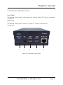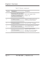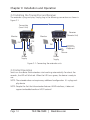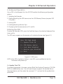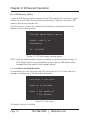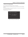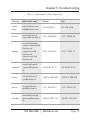
1
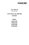
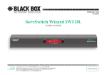
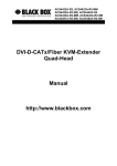
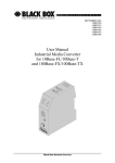
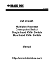
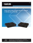
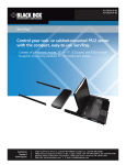
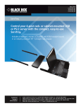
ACX300 ServSwitch™ CATx DVI + USB Extender EC Provides Full HD and USB extension BLACK BOX up to 328 feet (100 m) over CATx. ® Supports resolution up to 1920 x 1200. Customer Support Information Order toll-free in the U.S.: Call 877-877-BBOX (outside U.S. call 724-746-5500) • FREE technical support 24 hours a day, 7 days a week: Call 724-746-5500 or fax 724-746-0746 • Mailing address: Black Box Corporation, 1000 Park Drive, Lawrence, PA 15055-1018 Web site: www.blackbox.com • E-mail: [email protected] Trademarks Used in this Manual Trademarks Used in this Manual Black Box and the Double Diamond logo are registered trademarks, and ServSwitch is a trademark, of BB Technologies, Inc. HDMI is a registered trademark of HDMI Licensing, L.L.C. Windows is a registered trademark of Microsoft Corporation. Any other trademarks mentioned in this manual are acknowledged to be the property of the trademark owners. Page 2 724-746-5500 | blackbox.com FCC RFI and NOM Statements FEDERAL COMMUNICATIONS COMMISSION AND INDUSTRY CANADA RADIO FREQUENCY INTERFERENCE STATEMENTS This equipment generates, uses, and can radiate radio-frequency energy, and if not installed and used properly, that is, in strict accordance with the manufacturer’s instructions, may cause interference to radio communication. It has been tested and found to comply with the limits for a Class A computing device in accordance with the specifications in Subpart B of Part 15 of FCC rules, which are designed to provide reasonable protection against such interference when the equipment is operated in a commercial environment. Operation of this equipment in a residential area is likely to cause interference, in which case the user at his own expense will be required to take whatever measures may be necessary to correct the interference. Changes or modifications not expressly approved by the party responsible for compliance could void the user’s authority to operate the equipment. This digital apparatus does not exceed the Class A limits for radio noise emission from digital apparatus set out in the Radio Interference Regulation of Industry Canada. Le présent appareil numérique n’émet pas de bruits radioélectriques dépassant les limites applicables aux appareils numériques de classe A prescrites dans le Règlement sur le brouillage radioélectrique publié par Industrie Canada. Normas Oficiales Mexicanas (NOM)Electrical Safety Statement INSTRUCCIONES DE SEGURIDAD 1. Todas las instrucciones de seguridad y operación deberán ser leídas antes de que el aparato eléctrico sea operado. 2. Las instrucciones de seguridad y operación deberán ser guardadas para referencia futura. 3. Todas las advertencias en el aparato eléctrico y en sus instrucciones de operación deben ser respetadas. 724-746-5500 | blackbox.com Page 3 NOM Statement 4. Todas las instrucciones de operación y uso deben ser seguidas. 5. El aparato eléctrico no deberá ser usado cerca del agua—por ejemplo, cerca de la tina de baño, lavabo, sótano mojado o cerca de una alberca, etc. 6. El aparato eléctrico debe ser usado únicamente con carritos o pedestales que sean recomendados por el fabricante. 7. El aparato eléctrico debe ser montado a la pared o al techo sólo como sea recomendado por el fabricante. 8. Servicio—El usuario no debe intentar dar servicio al equipo eléctrico más allá a lo descrito en las instrucciones de operación. Todo otro servicio deberá ser referido a personal de servicio calificado. 9. El aparato eléctrico debe ser situado de tal manera que su posición no interfiera su uso. La colocación del aparato eléctrico sobre una cama, sofá, alfombra o superficie similar puede bloquea la ventilación, no se debe colocar en libreros o gabinetes que impidan el flujo de aire por los orificios de ventilación. 10.El equipo eléctrico deber ser situado fuera del alcance de fuentes de calor como radiadores, registros de calor, estufas u otros aparatos (incluyendo amplificadores) que producen calor. 11. El aparato eléctrico deberá ser connectado a una fuente de poder sólo del tipo descrito en el instructivo de operación, o como se indique en el aparato. 12. Precaución debe ser tomada de tal manera que la tierra fisica y la polarización del equipo no sea eliminada. 13. Los cables de la fuente de poder deben ser guiados de tal manera que no sean pisados ni pellizcados por objetos colocados sobre o contra ellos, poniendo particular atención a los contactos y receptáculos donde salen del aparato. 14.El equipo eléctrico debe ser limpiado únicamente de acuerdo a las recomendaciones del fabricante. 15. En caso de existir, una antena externa deberá ser localizada lejos de las lineas de energia. Page 4 724-746-5500 | blackbox.com NOM Statement 16.El cable de corriente deberá ser desconectado del cuando el equipo no sea usado por un largo periodo de tiempo. 17. Cuidado debe ser tomado de tal manera que objectos liquidos no sean derramados sobre la cubierta u orificios de ventilación. 18.Servicio por personal calificado deberá ser provisto cuando: A: El cable de poder o el contacto ha sido dañado; u B: Objectos han caído o líquido ha sido derramado dentro del aparato; o C: El aparato ha sido expuesto a la lluvia; o D: El aparato parece no operar normalmente o muestra un cambio en su desempeño; o E: El aparato ha sido tirado o su cubierta ha sido dañada. 724-746-5500 | blackbox.com Page 5 Table of Contents Table of Contents 1. Specifications.....................................................................................................7 2. Overview .....................................................................................................8 2.1 Introduction..............................................................................................8 2.2 Features.....................................................................................................8 2.3 What’s Included........................................................................................8 2.4 Hardware Description...............................................................................9 2.4.1 Transmitter (Local Unit)................................................................9 2.4.2 Receiver (Remote Unit)..............................................................11 3. Installation and Operation................................................................................13 3.1 Cable Requirements................................................................................13 3.2 Installing the Transmitter and the Receiver.............................................14 3.3 Initial Operation......................................................................................14 4. Enhanced Operations........................................................................................15 5. Troubleshooting................................................................................................18 5.1 Contacting Black Box..............................................................................18 5.2 Shipping and Packaging.........................................................................18 Page 6 724-746-5500 | blackbox.com Chapter 1: Specifications 1. Specifications Cascadable — No Computer Interface — HDMI® video, USB DDC Support — Internal DDC table Encryption — No Heat Dissipation — 3.41 BTU/hr. maximum Maximum Distance from CPU to TX — 16 feet (5 m), DVI-D and USB limitations Maximum Distance between TX and RX — 328 feet (100 m) Operating System Support — All OS, including Windows® Connectors — Transmitter: (2) HDMI F with HDMI to DVI-D adapter cable, (1) USB Type B F, (1) RJ-45 F, (1) DC power; Receiver: (1) HDMI F with HDMI to DVI-D adapter cable, (4) USB Type A F, (1) RJ-45 F, (1) DC power Indicators — Each unit (Transmitter or Receiver): (1) Power/Online LED Temperature Tolerance — Operating: 32 to 104° F (0 to 40° C); Storage: -4 to 158° F (-20 to +70° C) Humidity Tolerance — Operating: 80%, noncondensing Power — External inline power supply, Input: 100–240 VAC, 50/60 Hz, 0.5 A, Output: 12 VDC, 1 A Size — Each unit (Transmitter or Receiver): 1.6"H x 3.85"W x 4.17"D (4.1 x 9.8 x 10.6 cm) Weight — 1.1 lb. (0.5 kg) 724-746-5500 | blackbox.com Page 7 Chapter 2: Overview 2. Overview 2.1 Introduction The ServSwitch™ CATx DVI + USB Extender EC provides lossless Full HD and USB extension up to 328 feet (100 m) over CATx cable. It consists of two units: a transmitter and a receiver. The extender is plug-and-play, so there aren’t any complex installation instructions. And you don’t need to configure the unit, either. 2.2 Features • Supports USB keyboard/mouse, USB touchscreen, and other Human Interface Devices (HIDs). • Uses just one USB CAT5e/6/7 cable. • Provides remote monitoring. • Includes optional upgrade for extending USB storage media. • Sound and RS-232 expandable via external USB adapters. • Plug-and-play installation with DDC/EDID reading. • An optional mounting option for 19" racks with four units in (1) rack unit (RU) is available. • Can also be wall-, table-, or DIN-rail-mounted. Mounting options accessories are: ACX300-RMK: 19" Rackmounting Kit for up to 4 local or remote units. ACX300-TMK: Table and Wallmount Kit for either local or remote unit. ACX300-DRM: DIN-rail Mounting Kit for either local or remote unit. 2.3 What’s Included Your package should include the following items. If anything is missing or damaged, contact Black Box Technical Support at 724-746-5500 or [email protected]. • (1) transmitter • (1) receiver • (2) HDMI to DVI-D cables • This user’s manual Page 8 724-746-5500 | blackbox.com Chapter 2: Overview 2.4 Hardware Description 2.4.1 Transmitter (Local Unit) Front Panel The transmitter‘s front panel is blank except for a Power Status LED, which is described in Table 2-1. Back Panel The transmitter’s back panel is shown in Figure 2-1. Table 2-1 describes its components. 2 3 4 5 6 Figure 2-1. Transmitter’s back panel. 724-746-5500 | blackbox.com Page 9 Chapter 2: Overview Table 2-1. Transmitter’s components. Number Component Description 1 Power Status LED (not shown in Figure 2-1, located on the front panel of the transmitter) Lights when power to the transmitter is on. 2 (1) HDMI connector Connects to the PC. 3 (1) barrel connector Links to 12-VAC, 1-A power. 4 (1) HDMI connector Connects to PC IN port. 5 (1) USB Type B connector Links to USB port on the PC. 6 (1) RJ-45 connector Connects one end of the 328-foot (100-m) link between the transmitter and receiver. Page 10 724-746-5500 | blackbox.com Chapter 2: Overview 2.4.2 Receiver (Remote Unit) Front Panel The receiver’s front panel is blank except for a Power Status LED, which is described in Table 2-2. Back Panel The receiver’s back panel is shown in Figure 2-2. Table 2-2 describes its components. 2 3 4 4 5 Figure 2-2. Receiver’s back panel. 724-746-5500 | blackbox.com Page 11 Chapter 2: Overview Table 2-2. Receiver’s components. Number Component Description 1 Power Status LED (not shown in Figure 2-2, located on the front panel of the receiver) Lights when power to the receiver is on. 2 (1) HDMI connector Connects to DVI monitor with FA790 or to HDMI monitor. 3 (1) barrel connector Links to 12-VAC, 1-A power. 4 (4) USB Type A connectors Link to keyboard/mouse and two USB peripheral devices. 5 (1) RJ-45 connector Connects one end of the 328-foot (100-m) link between the receiver and transmitter. Page 12 724-746-5500 | blackbox.com Chapter 3: Installation and Operation 3. Installation and Operation 3.1 Cable Requirements Use CAT5/6/7 cable. The pins are connected 1:1. NOTE: B oth cable ends must comply with either EIA/TIA-568A or EIA-TIA-568B. If they don’t comply, a cable tester won’t find the cable pinnings. Pinning The pins of the green pair of wires are not together. The cable must be at least CAT5 standard and Gigabit transfer-ready. It should comply with ISO/IEC class D standards. Table 3-1. Cable pinning. Pin Color Connects to this pin Color 1 Orange/White 2 Orange 2 Orange 1 Orange/White 3 Green/White 6 Green 4 Blue 5 Blue/White 5 Blue/White 4 Blue 6 Green 3 Green/White 7 Brown/White 8 Brown 8 Brown 7 Brown/White NOTE: Use 24 AWG or larger shielded solid cable. Make sure that the shield is connected on both sides. You can also use shielded patch cable if the connection allows. 724-746-5500 | blackbox.com Page 13 Chapter 3: Installation and Operation 3.2 Installing the Transmitter and Receiver The extender is plug-and-play. Simply plug in the following connections as shown in Figure 3-1. Transmitter (Local Unit) Monitor Receiver (Remote Unit) Monitor DVI DVI DVI Keyboard Mouse PC Power Supply Power Supply Figure 3-1. Connecting the extender units. 3.3 Initial Operation Switch on the device. Both extenders start working automatically. For about five seconds, the LED will blink red. When the LED turns green, the device is ready to use. NOTE: The extender does not require any additional configuration. It’s a plug-andplay device. NOTE: Despite the fact that the extender features HDMI interfaces, it does not support embedded audio or HDCP content! Page 14 724-746-5500 | blackbox.com Chapter 4: Enhanced Operation 4. Enhanced Operation Via an OSD in the Remote Unit, the ACX300 enables the following configuration options: 1. Updating the Extender. 2. Enabling/disabling the USB transmission for USB Memory Devices (requires USB 2.0 option). 3. Locking OSD. 4. Enabling/disabling Monitor Sync. 5. Displaying the firmware versions of Tx and Rx. Entering the OSD To enter the Extenders OSD, press the ScrollLock key on the attached keyboard five times quickly. The OSD menu appears on the remote unit’s attached display (see Figure 4-1). Menu USB High Speed U = Update Flash FW M = USB Memory Option L = Lock Menu disabled I = Monitor sync disabled Q = Exit Figure 4-1. OSD menu. NOTE: If the OSD is locked via Option L, the OSD is only available for the first 10 minutes after power up. U =Update Flash FW To update the extender’s firmware, contact Black Box Technical Support at 724-7465500 or [email protected]. You will need to open a graphic file (update file) on the target device, and then enter the command “U” and wait for the update to be performed. 724-746-5500 | blackbox.com Page 15 Chapter 4: Enhanced Operation M = USB Memory Option Using the USB Memory Option command, the OSD provides the user with a cryptic code to be sent to Black Box to enable the license key. Then you can attach USB memory devices and transfer files. Once the license is active, this command will enable or disable the file transfer feature to restrict data transfer. USB High Speed Memory Option Enable: send ID to distributor ID = 3fe687d5 Figure 4-2. USB high-speed memory option. NOTE: Once the memory device option is enabled, using the extender on top of a KVM Switch might cause compatibility issues since the USB mode will be changed from low speed to high speed protocol. L = Lock Menu enabled/disabled Once enabled, you can only enter the OSD during the first 10 minutes after the remote unit powers up. It will be locked afterwards. Lock Menu 10 Min after Power-On is Disabled Enter 1 for enable or 0 for disable Figure 4-3. Lock menu. The default setting is disabled. Page 16 724-746-5500 | blackbox.com Chapter 4: Enhanced Operation I = Monitor sync enabled/disabled You can activate or deactivate the monitor synchronization. If enabled, the graphics card refresh rates are synchronized with the (Rx) attached monitors. This will optimize motion picture content applications, but might not work properly with all monitors (flicker may occur). The default setting is disabled. Monitor sync disabled Enter 1 for enable or 0 for disable Figure 4-4. Monitor sync disabled screen. 724-746-5500 | blackbox.com Page 17 Chapter 5: Troubleshooting 5. Troubleshooting 5.1 Contacting Black Box If you determine that your ServSwitch CATx DVI + USB Extender EC is malfunctioning, do not attempt to alter or repair the unit. It contains no user-serviceable parts. Contact Black Box Technical Support: • Email in the US: [email protected] in the UK: [email protected] • Phone in the US: 724-746-5500 in the UK: +44 (0)118 965 6000 NOTE: See Table 5-1 for a list of international contact information. Before you do, make a record of the history of the problem. We will be able to provide more efficient and accurate assistance if you have a complete description, including: • the nature and duration of the problem. • when the problem occurs. • the components involved in the problem. • any particular application that, when used, appears to create the problem or make it worse. 5.2 Shipping and Packaging If you need to transport or ship your ServSwitch CATx DVI + USB Extender EC: • Package it carefully. We recommend that you use the original container. • If you are returning the unit, make sure you include everything you received with it. Before you ship for return or repair, contact Black Box to get a Return Authorization (RA) number. Page 18 724-746-5500 | blackbox.com Chapter 5: Troubleshooting Table 5-1. International Contact Information. Country Web site/E-mail Phone Fax United States www.blackbox.com [email protected] 724-746-5500 724-746-0746 Austria www.black-box.at [email protected] +43 1 256 98 56 +43 1 256 98 56 Belgium www.blackbox.be support.nederlands@ blackbox.be support.french@ blackbox.be support.english@ blackbox.be +32 2 725 85 50 +32 2 725 92 12 Denmark www.blackbox.dk support@blackbox. dk +45 56 63 30 10 +45 56 65 08 05 Finland www.blackbox.fi [email protected] +358 201 888 800 +358 201 888 808 France www.blackbox.fr [email protected] +33 1 45 606 717 +33 1 45 606 747 Germany www.black-box.de techsupp@black-box. de +49 811 5541 110 +49 811 5541 499 724-746-5500 | blackbox.com Page 19 Chapter 5: Troubleshooting Table 5-1 (continued). International Contact Information. Country Web site/E-mail Phone Fax Italy www.blackbox.it supporto.tecnico@ blackbox.it +39 02 27 404 700 +39 02 27 400 219 Netherlands www.blackbox.nl techsupport@ blackbox.nl +31 30 241 7799 +31 30 241 4746 Norway www.blackbox norge.no support@ blackboxnorge.no +47 55 300 710 +47 55 300 701 Spain www.blackbox.es [email protected] +34 9162590732 +34 916239784 Sweden www.blackboxab.se support@ blackboxab.se +46 8 44 55 890 +46 08 38 04 30 Switzerland www.black-box.ch support@black-box. ch +41 55 451 70 71 +41 55 451 70 75 UK www.blackbox.co.uk techhelp@blackbox. co.uk +44 118 965 6000 +44 118 965 6001 Ireland www.blackbox.co.uk techhelp@blackbox. co.uk +353 1 662 2466 +353 1 662 2477 Page 20 724-746-5500 | blackbox.com NOTES 724-746-5500 | blackbox.com Page 21 NOTES Page 22 724-746-5500 | blackbox.com NOTES 724-746-5500 | blackbox.com Page 23 Chapter Black Box Tech Support: FREE! Live. 24/7. Tech support the way it should be. Great tech support is just 30 seconds away at 724-746-5500 or blackbox.com. About Black Box Black Box provides an extensive range of networking and infrastructure products. You’ll find everything from cabinets and racks and power and surge protection products to media converters and Ethernet switches all supported by free, live 24/7 Tech Support available in 30 seconds or less. © Copyright 2012. Black Box Corporation. All rights reserved. ACX300, version 1 Page 900 724-746-5500 | blackbox.com