1
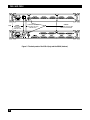
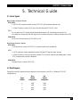
SEPTEMBER 1998
TL304A
TL305A
PSD-4
PSD-8
CUSTOMER
SUPPORT
INFORMATION
Order toll-free in the U.S.: Call 877-877-BBOX (outside U.S. call 724-746-5500)
FREE technical support 24 hours a day, 7 days a week: Call 724-746-5500 or fax 724-746-0746
Mailing address: Black Box Corporation, 1000 Park Drive, Lawrence, PA 15055-1018
Web site: www.blackbox.com • E-mail: [email protected]
FCC STATEMENT
FEDERAL COMMUNICATIONS COMMISSION
AND
INDUSTRY CANADA
RADIO FREQUENCY INTERFERENCE STATEMENTS
This equipment generates, uses, and can radiate radio-frequency energy, and if not installed and used
properly, that is, in strict accordance with the manufacturer’s instructions, may cause interference to radio
communication. It has been tested and found to comply with the limits for a Class A computing device in
accordance with the specifications in Subpart B of Part 15 of FCC rules, which are designed to provide
reasonable protection against such interference when the equipment is operated in a commercial
environment. Operation of this equipment in a residential area is likely to cause interference, in which
case the user at his own expense will be required to take whatever measures may be necessary to correct
the interference.
Changes or modifications not expressly approved by the party responsible for compliance could void the user’s
authority to operate the equipment.
This digital apparatus does not exceed the Class A limits for radio noise emission from digital apparatus set out in the Radio
Interference Regulation of Industry Canada.
Le présent appareil numérique n’émet pas de bruits radioélectriques dépassant les limites applicables aux appareils numériques
de la classe A prescrites dans le Règlement sur le brouillage radioélectrique publié par Industrie Canada.
1
PSD-4 AND PSD-8
INSTRUCCIONES DE SEGURIDAD (Normas Oficiales Mexicanas Electrical Safety Statement)
1. Todas las instrucciones de seguridad y operación deberán ser leídas antes de que el aparato eléctrico sea operado.
2. Las instrucciones de seguridad y operación deberán ser guardadas para referencia futura.
3. Todas las advertencias en el aparato eléctrico y en sus instrucciones de operación deben ser respetadas.
4. Todas las instrucciones de operación y uso deben ser seguidas.
5. El aparato eléctrico no deberá ser usado cerca del agua—por ejemplo, cerca de la tina de baño, lavabo, sótano
mojado o cerca de una alberca, etc..
6. El aparato eléctrico debe ser usado únicamente con carritos o pedestales que sean recomendados por el fabricante.
7. El aparato eléctrico debe ser montado a la pared o al techo sólo como sea recomendado por el fabricante.
8. Servicio—El usuario no debe intentar dar servicio al equipo eléctrico más allá a lo descrito en las instrucciones de
operación. Todo otro servicio deberá ser referido a personal de servicio calificado.
9. El aparato eléctrico debe ser situado de tal manera que su posición no interfiera su uso. La colocación del aparato
eléctrico sobre una cama, sofá, alfombra o superficie similar puede bloquea la ventilación, no se debe colocar en
libreros o gabinetes que impidan el flujo de aire por los orificios de ventilación.
10. El equipo eléctrico deber ser situado fuera del alcance de fuentes de calor como radiadores, registros de calor, estufas
u otros aparatos (incluyendo amplificadores) que producen calor.
11. El aparato eléctrico deberá ser connectado a una fuente de poder sólo del tipo descrito en el instructivo de
operación, o como se indique en el aparato.
12. Precaución debe ser tomada de tal manera que la tierra fisica y la polarización del equipo no sea eliminada.
13. Los cables de la fuente de poder deben ser guiados de tal manera que no sean pisados ni pellizcados por objetos
colocados sobre o contra ellos, poniendo particular atención a los contactos y receptáculos donde salen del aparato.
14. El equipo eléctrico debe ser limpiado únicamente de acuerdo a las recomendaciones del fabricante.
15. En caso de existir, una antena externa deberá ser localizada lejos de las lineas de energia.
16. El cable de corriente deberá ser desconectado del cuando el equipo no sea usado por un largo periodo de tiempo.
17. Cuidado debe ser tomado de tal manera que objectos liquidos no sean derramados sobre la cubierta u orificios de
ventilación.
18. Servicio por personal calificado deberá ser provisto cuando:
A: El cable de poder o el contacto ha sido dañado; u
B: Objectos han caído o líquido ha sido derramado dentro del aparato; o
C: El aparato ha sido expuesto a la lluvia; o
D: El aparato parece no operar normalmente o muestra un cambio en su desempeño; o
E: El aparato ha sido tirado o su cubierta ha sido dañada.
2
TRADEMARKS
TRADEMARKS USED IN THIS MANUAL
AS/400 is a registered trademark of International Business Machines Corporation.
Any other trademarks mentioned in this manual are acknowledged to be the property of the trademark owners.
3
PSD-4 AND PSD-8
1. Specifications
Number of Sub-Channels —
PSD-4:
4
PSD-8:
8
Channel Configuration —
Lowest Priority:
Highest Priority:
Sub-channel 1
PSD-4: Sub-channel 4
PSD-8: Sub-channel 8
Sub-Channel Selection — RTS/DCD on or data transitions (strap-selectable)
Sub-Channel Deselection — RTS/DCD off or 16 bits of idle data (strap-selectable)
Sub-Channel Dialing —
Manual:
Press in the front-panel pushbutton switch
Automatic:
If a sub-channel stays connected for more than a pre-set period of time
(strap-selectable—1.7, 13.5, or 108), the PSD automatically disables it
Clock Source — Internal, external from main channel, or external from sub-channel 1
Data Rates —
Asynchronous:
Synchronous:
Up to 19.2 kbps
Internal Clock: 1.2, 2.4, 4.8, 7.2, 9.6, 14.4, or 19.2 kbps
External Clock: Up to 19.2 kbps
Connectors — IEIA RS-232-C/CCITT V.24; DCE or DTE (strap-selectable)
Controls — Front-panel SUB-CHANNEL DISABLE pushbutton switch for each sub-channel; rear-panel
POWER rocker switch; rear-panel 110/220 VAC selector
LED Indicators —
POWER:
DATA:
Lights when the unit is receiving AC power
Lights when data is broadcast from the main channel
to the sub-channels
ACTIVITY:
Lights when the sub-channel accesses the main channel
AUTOMATIC: Lights when sub-channel has been automatically disabled
Temperature — 32 to 122°F (0 to 50°C)
Humidity — 30 to 90%, non-condensing
Power — 110/220 VAC switchable + 10%
Size — I1.7"H x 17"W x 8.2"D (4.3 x 43.1 x 20.8 cm)
Weight — 4.4 lb (2.0 kg)
4
CHAPTER 2: Introduction
2. Introduction
The Programmable Sharing Device enables up to 4 (TL304A) or 8 (TL305A) modems or terminals to share
a master modem, multiplexor, or computer port in an asynchronous or synchronous multipoint environment.
(Asynchronous and synchronous equipment cannot be mixed on the same PSD.)
MAIN CHANNEL
The main channel transmits information to all sub-channels in parallel.
SUB-CHANNELS
Sub-channels contend to transmit to the main channel by activating RTS/DCD (Request to Send/Data Carrier
Detect) or by data transitions (strap-selectable). When the sub-channel is active, the sub-channel’s transmit data
and control signals are connected to the main channel. When RTS/DCD drops, data transitions stop, or 16 idle
bits are received, the PSD will disconnect and monitor other sub-channels.
Sub-channels can be disabled either manually by front-panel pushbuttons or automatically. If a sub-channel
is streaming and staying active for longer than a configured amount of time, the PSD will automatically disable
that sub-channel. A front-panel LED will illuminate to indicate that the sub-channel has been automatically
disabled. The sub-channel will be reset when RTS/DCD drops or 16 idle bits are transmitted to it from the
attached device.
CLOCK MODES
Three clock modes are supported: internal, external from the main channel, or external from sub-channel 1.
BUFFER
A built-in-buffer compensates for phase differences between the clocks of modems connected to the subchannels and the PSD main-channel transmit clock.
An extra-buffer option on the PSD-8 can be activated when the PSD is connected to equipment that cannot
accept an external clock. Examples include DDs (United States) or other digital lines and modems that cannot
be set to an external clock. This additional buffer compensates for phase differences between the PSD clock
and sub-channel clock(s).
RS-232 Cable
RS-232 Cable
Controllers
Modem
Dialup Line
Modem
PSD-4
Modem
Leased Line
Modem
AS/400®
CSU/DSU
Leased Line
CSU/DSU
Figure 1. The Programmable Sharing Device allows multiple devices to share a master port.
5
PSD-4 AND PSD-8
3. Installation
3.1 Choosing a Site
• The PSD must be installed within five feet (1.5 m) of a grounded AC outlet.
• The PSD must be within 50 feet (15 m) of the equipment that will be attached to the main channel and
each sub-channel.
• Allow 36 inches (91 cm) frontal clearance for operating and maintenance accessibility.
• Allow four inches (10 cm) rear-panel clearance for the power and interface cables.
• Side-panel brackets can be used to install the unit in a 19" rack. (The brackets can be removed without
harming the PSD.)
3.2 Configuring the PSD Printed Circuit Board
Table 1 on the following page explains each of the configurable jumpers or switches on the PSD printed circuit
board. Figures 3 and 4 show the locations of each of the jumpers and switches for the PSD-4 and PSD-8.
There are two EXT. BUFFER switches on the PSD-8. These are extra buffers—not external buffers. Use the
extra buffers when the PSD is connected to equipment that cannot accept an external clock from the PSD.
The extra buffers compensate for phase differences between clocks. There are many applications where this
might be necessary, but one example would be where multiple CSU/DSUs (each attached to its own leased
line that provides clocking) are connected to the PSD.
Switch S1 controls the buffer for sub-channels 1 through 4, and switch S2 controls the buffer for sub-channels 5
through 8.
POWER:
Lights when
the unit is
receiving
AC power
DATA:
Lights when
data is broadcast
from the main
channel to the
sub-channels
ACTIVITY:
Lights when the
sub-channel
accesses the
main channel.
SUB-CHANNEL
DISABLE:
Press in the push button
to manually disable a
sub-channel.
AUTOMATIC:
Lights when subchannel has been
automatically
disabled.
Figure 2. The front panels of the PSD-4 (top) and the PSD-8 (bottom).
6
CHAPTER 3: Installation
Table 1. Printed Circuit-Board Switch and Strap Settings
Possible
Settings
Factory
Setting
MAIN DCE/DTE switch
DTE
DCE
DTE
Determines the PSD’s Main Channel
interface as either DTE (straight connection
to a modem) or as DCE (straight connection
to a computer or terminal).
Sub-channel
DCE/DTE switches
DTE
DCE
DTE
Determines the PSD’s sub-channel interface
as either DTE or DCE.
19.2
14.4
9.6
7.2
4.8
2.4
1.2
CLK 1
9.6
Stap Identity
DATA RATE (kbps)
(rotary switch)
Location
BR1
Function
Selects the PSD’s internal data rate or external
clock from sub-channel 1.
NOTE: When using CLK 1 mode, the main
channel cannot be connected to a modem
working in internal clock.
Chas. GND
J1
CONNECT
DISCONNECT The CONNECT setting connects signal ground
DISCONNECT
to chassis ground. The DISCONNECT setting
isolates them.
PIN 24 DIS
J1A
ENABLE
(jumpered)
DISABLE
(NO jumper)
ENABLE
Exits main channel when PIN 24 is disabled.
TIME OUT
J2
1.7
13.5
108
DISABLE
108
Selects the time-out period (in seconds) after
which the PSD will automatically disable the
sub-channel. Selecting DISABLE will stop
the PSD from automatically disabling any
sub-channels.
CONTENTION
J5
RTS
DATA
RTS
Determines the sub-channel selection and
deselection.
FORMAT
J6
ASYNC
SYNC
SYNC
CLOCK
J7
NORMAL
FROM EXT DTE
NORMAL
EXT. BUFFER
(PSD-8 only)
S1
S2
ON
OFF
OFF
Selects the data format.
Determines the source of the clock for
synchronous data. Set to NORMAL for
internally derived clock. Set to FROM EXT
DTE for externally dermined clock from a
connected DTE.
Activates or deactivates the extra buffer.
7
PSD-4 AND PSD-8
Figure 3. The Printed Circuit Board of the PSD-4.
Figure 4. The Printed Circuit Board of the PSD-8.
8
CHAPTER 3: Installation
3.3 System Synchronization
ASYNCHRONOUS MODE
Strap the J6 jumper over the ASYNC pins. All attached equipment must be asynchronous. Turn the BIT RATE
rotary switch (BRI) to the correct system speed. No other adjustments to the PSD are necessary.
SYNCHRONOUS MODE
Strap the J6 jumper over the SYNC pins (this is the factory-default setting). All attached equipment must be
synchronous. There are four ways to synchronize the system:
1. Synchronization on the PSD’s internal clock.
• Main channel: Equipment attached to the main channel should be set to external clock.
• Sub-channel: Equipment attached to the sub-channels should be set to external clock.
• BIT RATE rotary switch: Set BRI to the correct system speed.
2. Synchronization on the equipment attached to the main channel.
• Main channel: Equipment attached to the main channel should be set to internal clock.
• Sub-channels: Equipment attached to the sub-channels should be set to external clock.
• BIT RATE rotary switch: Set BRI to the correct system speed.
• Jumper J7: If the equipment attached to the main channel is DCE, strap to NORMAL. If the equipment is
DTE, strap to FROM EXT DTE.
3. Synchronization on the equipment attached to sub-channel 1.
• Main channel: Equipment attached to the main channel should be set to external clock.
• Sub-channel 1: Equipment attached to sub-channel 1 should be set to internal clock.
• Sub-channel 2 through 8: Equipment attached to the sub-channels 2 through 8 should be set to external
clock.
• BIT RATE rotary switch: Set BRI to position 7 (CLK1).
• Jumper J7: If the equipment attached to the sub-channel 1 is DCE, strap to NORMAL. If the equipment
is DTE, strap to FROM EXT DTE.
NOTE: Synchronization on sub-channel 1 is not recommended when the device attached to sub-channel
1 operates in switched carrier mode. This will cause fluctuations in clock frequency and phase.
4. Synchronization on equipment attached to any sub-channel (PSD-8 only).
• Main channel: Equipment attached to the main channel can be set to internal or external clock.
• Sub-channels: Equipment attached to the sub-channels can be set to internal or external clock.
9
PSD-4 AND PSD-8
• BIT RATE rotary switch: Set BRI to the correct system speed.
• EXT. BUFFER: If any of the devices connected to the sub-channels numbered 1 through 4 are set to
internal clock, then switch S1 should be ON. If any of the devices connected to the sub-channels numbered
5 through 8 are set to internal clock, then switch S2 should be ON.
• Jumper J7: If the equipment attached to the sub-channel 1 is DCE, strap to NORMAL. If the equipment is
DTE, strap to FROM EXT DTE.
3.4 AC Power
On the rear panel of your unit, locate the 110/220 VAC selector. Set the selctor to match your main power
source.
After configuration is complete and the cover to the unit is replaced, plug the power cord into the PSD. Plug
the other end into a grounded AC power jack.
NOTE: There is a 0.25A slow-blow fuse in your unit. Do not replace this fuse with a repaired fuse.
Do not short-circuit the fuse holder.
Turn the POWER rocker switch on.
10
CHAPTER 4: Operation and Troubleshooting
4. Operation and Troubleshooting
4.1 Operation
Turn on the rear-panel POWER rocker switch. The front-panel POWER LED will light.
The PSD operates automatically. Except for manually disabling a sub-channel, you will not need
to attend to the PSD.
4.2 Changing Setting During Operation
If you have to reconfigure the PSD for a different type of operation, turn off the PSD and unplug it from its AC
power source before taking off the cover to change settings.
4.3 Troubleshooting
POWER SUPPLY
If the unit is attached to an AC power source and the green Power LED does not light up, check the following:
• Make sure the rear-panel rocker switch is on and is lit.
• Verify that the 110/220 selector is set correctly.
• Unplug the unit and check the fuse (see Figure 5 for location of the fuse).
• Remove the top cover and verify that the 4-pin power connector is attached to the transformer on the
printed circuit board (PSD-8 only).
PSD MALFUNCTION
If the Power LED is lit, but the PSD is not functioning, unplug your unit. Take off the cover and check the
following:
• Verify that all the DCE/DTE switches are set according to the data-system requirements.
• Double-check each of your strap settings.
• Visually inspect the large chips labeled RJ-006. Make sure that they are securely attached to the printed
circuit board.
11
PSD-4 AND PSD-8
FUSE
POWER:
Rocker switch
to turn AC
power on or off
110/220 VAC Selector:
Align either 110 or 220
with the arrow.
SCREWS:
Loosen these screws to take
off the cover of the PSD.
Figure 5. The back panels of the PSD-4 (top) and the PSD-8 (bottom).
12
CHAPTER 5: Technical Guide
5. Technical Guide
5.1 Control Signals
MAIN CHANNEL CONTROL SIGNALS
RTS (DCD)
• In RTS/DCD contention mode: follows RTS (DCD) of the selected sub-channels.
• In Data Contention mode: ON if one of the sub-channels RTS (DCD) is ON.
CTS
On only when the CTS signals of all active sub-channels are ON. A sub-channel is active if it is
connected to a modem and the DSR signal is ON (enables connection of dialup modems to the PSD).
DSR (DTR)
ON if one of the sub-channel’s DTR (DSR) is ON.
SUB-CHANNEL CONTROL SIGNALS
RTS (DCD)
• Follows the main channel RTS (DCD) (unless the sub-channel is disabled).
CTS
• In RTS contention mode: selected sub-channel follows DTS signal of main channel.
• In Data Contention mode: sub-channel receives CTS from main channel immediately after it raises
RTS (unless the sub-channel is disabled).
DSR (DTR)
Follows the main channel DSR (DTR).
5.2 Block Diagrams
Figures 6 through 9 illustrate the flow of data and control signals in the PSD, in different DTE/DCE
configurations:
Figure
Number
Main
Channel
Configuration
SubChannel
Configuration
6
7
8
9
DTE
DTE
DCE
DCE
DCE
DTE
DCE
DTE
13
PSD-4 AND PSD-8
Figure 6. Main Channel DTE with Sub-Channel DCE.
Figure 7. Main Channel DTE with Sub-Channel DTE.
14
CHAPTER 5: Technical Guide
Figure 8. Main Channel DCE with Sub-Channel DCE.
Figure 9. Main Channel DCE with Sub-Channel DTE.
15
© Copyright 1998. Black Box Corporation. All rights reserved.
1000 Park Drive
•
Lawrence, PA 15055-1018
•
724-746-5500
•
Fax 724-746-0746