1
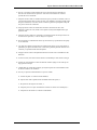
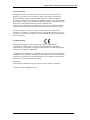
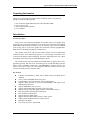
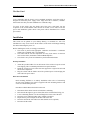
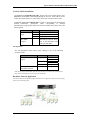
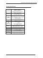
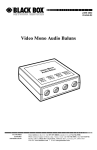
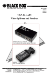
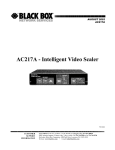
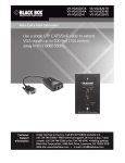
Dec, 2006
Express
Ethernet Switch
LGB316A-R2
LGB324A-R2
CUSTOMER
SUPPORT
INFORMATION
Order toll-free in the U.S. Call : 877-877-BBOX ( Outside U. S. call 724-746-5500 )
FREE technical support 24 hours a day, 7 days a week: Call 724-746-5500 or fax
724-746-0746
Mailing address: Black Box Corporation, 1000 Park Drive, Lawrence, PA 15055-1018
Web site: www.blackbox.com • E-mail: [email protected]
Express Ethernet Switch LGB316A-R2, LGB324A-R2
FEDERAL COMMUNICATIONS COMMISSION AND
CANADIAN DEPARTMENT OF COMMUNICATIONS
RADIO FREQUENCY INTERFERENCE STATEMENT
Class B Digital Device. This equipment has been tested and found to comply with the limits for a
Class B computing device pursuant to Part 15 of the FCC Rules. These limits are designed to
provide reasonable protection against harmful interference in a residential installation. However,
there is no guarantee that interference will not occur in a particular installation. This equipment
generates, uses, and can radiate radio frequency energy, and, if not installed and used in
accordance with the instructions, may cause harmful interference to radio communications. If this
equipment does cause harmful interference to radio or telephone reception, which can be
determined by turning the equipment off and on, the user is encouraged to try to correct the
interference by one of the following measures:
• Reorient or relocate the receiving antenna.
• Increase the separation between the equipment and receiver.
• Connect the equipment into an outlet on a circuit different from that to which the receiver is
connected.
• Consult an experienced radio/TV technician for help.
Caution:
Changes or modifications not expressly approved by the party responsible for
compliance could void the user’s authority to operate the equipment.
To meet FCC requirements, shielded cables and power cords are required to connect this device
to a personal computer or other Class B certified device.
This digital apparatus does not exceed the Class B limits for radio noise emission from digital
apparatus set out in the Radio Interference Regulation of the Canadian Department of
Communications.
Le présent appareil numérique n’émet pas de bruits radioélectriques dépassant les limites
applicables aux appareils numériques de la classe B prescrites dans le Règlement sur le
brouillage radioélectrique publié par le ministère des Communications du Canada.
Normas Oficiales Mexicanas (NOM)
INSTRUCCIONES DE SEGURIDAD
1. Todas las instrucciones de seguridad y operación deberán ser leídas antes de que el
aparato eléctrico sea operado.
2. Las instrucciones de seguridad y operación deberán ser guardadas para referencia futura.
3. Todas las advertencias en el aparato eléctrico y en sus instrucciones de operación deben
ser respetadas.
4. Todas las instrucciones de operación y uso deben ser seguidas.
5. El aparato eléctrico no deberá ser usado cerca del agua—por ejemplo, cerca de la tina de
baño, lavabo, sótano mojado o cerca de una alberca, etc.
6. El aparato eléctrico debe ser usado únicamente con carritos o pedestales que sean
recomendados por el fabricante.
7. El aparato eléctrico debe ser montado a la pared o al techo sólo como sea recomendado
por el fabricante.
2
Express Ethernet Switch LGB316A-R2, LGB324A-R2
8. Servicio—El usuario no debe intentar dar servicio al equipo eléctrico más allá a lo
descrito en las instrucciones de operación. Todo otro servicio deberá ser referido a
personal de servicio calificado.
9. El aparato eléctrico debe ser situado de tal manera que su posición no interfiera su uso. La
colocación del aparato eléctrico sobre una cama, sofá, alfombra o superficie similar puede
bloquea la ventilación, no se debe colocar en libreros o gabinetes que impidan el flujo de
aire por los orificios de ventilación.
10. El equipo eléctrico deber ser situado fuera del alcance de fuentes de calor como
radiadores, registros de calor, estufas u otros aparatos (incluyendo amplificadores) que
producen calor.
11. El aparato eléctrico deberá ser connectado a una fuente de poder sólo del tipo descrito en
el instructivo de operación, o como se indique en el aparato.
12. Precaución debe ser tomada de tal manera que la tierra fisica y la polarización del equipo
no sea eliminada.
13. Los cables de la fuente de poder deben ser guiados de tal manera que no sean pisados ni
pellizcados por objetos colocados sobre o contra ellos, poniendo particular atención a los
contactos y receptáculos donde salen del aparato.
14. El equipo eléctrico debe ser limpiado únicamente de acuerdo a las recomendaciones del
fabricante.
15. En caso de existir, una antena externa deberá ser localizada lejos de las lineas de energia.
16. El cable de corriente deberá ser desconectado del cuando el equipo no sea usado por un
largo periodo de tiempo.
17. Cuidado debe ser tomado de tal manera que objectos liquidos no sean derramados sobre
la cubierta u orificios de ventilación.
18. Servicio por personal calificado deberá ser provisto cuando:
A: El cable de poder o el contacto ha sido dañado; u
B: Objectos han caído o líquido ha sido derramado dentro del aparato; o
C: El aparato ha sido expuesto a la lluvia; o
D: El aparato parece no operar normalmente o muestra un cambio en su desempeño; o
E: El aparato ha sido tirado o su cubierta ha sido dañada.
3
Express Ethernet Switch LGB316A-R2, LGB324A-R2
FCC Certifications
This Equipment has been tested and found to comply with the limits for a Class A
digital device, pursuant to part 15 of the FCC Rules. These limits are designed to
provide reasonable protection against harmful interference when the equipment is
operated in a commercial environment. This equipment generates, uses, and can radiate
radio frequency energy and, if not installed and used in accordance with the instruction
manual, may cause harmful interference to radio communications.
Operation of this equipment in a residential area is likely to cause harmful interference
in which case the user will be required to correct the interference at his own expense.
This device complies with Part 15 of the FCC Rules. Operation is subject to the
following two conditions: (1) this device may not cause harmful interference, and (2)
this device must accept any interference received; including interference that may cause
undesired operation.
CE Mark Warning
This equipment complies with the requirements relating to electromagnetic
compatibility, EN 55022 class A for ITE, the essential protection requirement of
Council Directive 89/336/EEC on the approximation of the laws of the Member States
relating to electromagnetic compatibility.
Company has an on-going policy of upgrading its products and it may be possible that
information in this document is not up-to-date. Please check with your local distributors
for the latest information. No part of this document can be copied or reproduced in any
form without written consent from the company.
Trademarks:
All trade names and trademarks are the properties of their respective companies.
Copyright © 2006, All Rights Reserved.
4
Express Ethernet Switch LGB316A-R2, LGB324A-R2
Unpacking Information
Thank you for purchasing this product. Before installation, please verify that your
package contains the following items.
1.
2.
3.
4.
One 16/24-Port Gigabit Ethernet Switch with 4-Port Mini-GBIC
One AC power cord
Rack-mount brackets (optional)
User’s Manual
Introduction
General Description
Easily boost your networking throughput; the product equips 16/24 Gigabit ports
that lead you to a real Gigabit connection. Users are now able to transfer large and high
bandwidth-needed files faster and hence get a real efficiency improvement. In addition
to the cooper ports, 4 of the ports supports fiber connection with the equipped MiniGBIC ports for obtaining long-distance communication.
This product offers users with fast and reliable network. The store-and-forward
architecture filters errors and forwards packets in a non-blocking environment. Flow
control prevent data loss while transmitting. The 802.3x and backpressure flow control
mechanisms work respectively for full and half duplex modes.
The switch features with easy installation and maintenance. It supports Nway autonegotiation protocol that detects the networking speed (10/100/1000 Mbps) and the
duplex modes (Full/Half) automatically. Auto-MDI/MDI-X function alleviates the
effort to use crossover cables. Also, rich diagnostic LEDs are provided for users to get
real-time information of the connection status.
Key Features
z
z
z
z
z
z
z
z
z
z
z
z
z
z
Complies with IEEE802.3, IEEE 802.3u, IEEE 802.3ab and IEEE 802.3z
standards.
16/24 * 10/100/1000 Mbps RJ-45 Nway ports
4* Mini-GBIC port for optional fiber optical communication
Supports NWay protocol for speed (10/100/1000Mbps) and duplex mode
(Half/Full) auto-detection
Supports MDI/MDI-X auto crossover
Supports full and half duplex operation on all copper ports
Supports back-pressure (half duplex) and flow control (IEEE 802.3x)
Wire-speed packet filtering and forwarding rate
Store-and-forward architecture
Supports 9K bytes Jumbo frame.
Supports 8K bytes MAC address entries in whole system
340K(16-Port) \500K(24-Port) bytes buffer memory
Internal power adapter
FCC,VCCI,CE Class A. Meet RoHS
5
Express Ethernet Switch LGB316A-R2, LGB324A-R2
The Front Panel
The front panel consists of LED indicators. For detailed LED definition, please refer to
the next paragraph.
LEDs Definition
System LED
LED
Power
Status
Steady Green
Off
Operation
The switch is powered on
The switch is powered off
Port LEDs
LED
Status
Steady Green
Operation
Valid port connection at 1000 Mbps
Valid port connection and there is
1000M Blinking Green data transmitting/ receiving
Port disconnected or the port is
Off
connected at 10 Mbps or 100 Mbps
Valid port connection at 10/ 100
Steady Green
Mbps
10/
Valid port connection and there is
Blinking Green
100M
data transmitting/ receiving
Port disconnected or the port is
Off
connected at 1000 Mbps
Attention : The Mini GBIC slot shares the same LED
indicators with Gigabit RJ-45 (copper) ports.
6
Express Ethernet Switch LGB316A-R2, LGB324A-R2
The Rear Panel
Power Receptacle
To be compatible with the electric service standards around the world, the switch is
designed to afford the power supply in the range from 100 to 240VAC, 50/60Hz.
Please make sure that your outlet standard to be within this range.
To power on the switch, plug the female end of the power cord firmly into the
receptacle of the switch and the other end into an electric service outlet. After the
power cord installation, please check if the power LED is illuminated for a normal
power status.
Installation
This switch can be placed on your desktop directly, or mounted in a rack. The
installation is a snap. Users can use all the features of the switch with simply attaching
the cables and turning the power on.
Before installing the switch, we strongly recommend:
1. The switch is placed with appropriate ventilation environment. A minimum
25mm space around the unit is recommended.
2. The switch and the relevant components are away from sources of electrical
noise such as radios, transmitters and broadband amplifiers
3. The switch is away from environments beyond recommend moisture
Desktop Installation
1.
2.
3.
Attach the provided robber feet to the bottom of the switch to keep the switch
from slipping. The recommend position has been square-marked.
Install the switch on a level surface that can support the weight of the unit and
the relevant components.
Plug the switch with the female end of the provided power cord and plug the
male end to the power outlet.
Rack-mount Installation
Rack mounting facilitate to an orderly installation when series of networking
devices being installed. The switch is supplied with rack mounting brackets and
screws for rack mounting the unit.
Procedures to Rack-Mount the Switch in the rack:
1.
2.
3.
4.
5.
6.
7.
Disconnect all the cables from the switch before continuing.
Place the unit the right way up on a hard, flat surface with the front facing you.
Locate a mounting bracket over the mounting holes on one side of the unit.
Insert the screws and fully tighten with a suitable screwdriver.
Repeat the two previous steps for the other side of the unit.
Insert the unit into the rack and secure with suitable screws (optional).
Reconnect all the cables.
7
Express Ethernet Switch LGB316A-R2, LGB324A-R2
Network Cables Installation
1. Crossover or straight-through cable: All the ports on the switch support AutoMDI/MDI-X functionality. Both straight-through or crossover cables can be used to
connect the switch with PCs as well as other devices like switches, hubs or router.
2. Category 3,4,5 or 5e UTP/STP cable: To make a valid connection and obtain the
optimal performance. Appropriate cables corresponding to different
transmitting/receiving speed is required. To choose a suitable cable, please refer to the
following table.
Media
Speed
10/100/1000Mbps 10Mbps
copper
100Mbps
1000Mbps
1000Mbps Fiber 1000Mbps
(Mini GBIC
required)
Wiring
Category 3,4,5 Utp/STP
Category 5 UTP/STP
Category 5,5e UTP/STP
The cable type differs from the
mini-GBIC you choose. Please
refer to the instruction came
with your mini-GBIC.
Port Operation
The auto-negotiation feature allows ports running at one of the following
operation modes:
Media
10/100/1000Mbps
(copper)
Speed
10Mbps
100Mbps
1000Mbps(Fiber)
(mini GBIC required)
1000Mbps
1000Mbps
Duplex Mode
Full Duplex
Half Duplex
Full Duplex
Half Duplex
Full Duplex
Full Duplex
Note: For the last port, when both the fiber and cooper interfaces are connected, the system adapts the
fiber interface and disables the relevant cooper port automatically.
Backbone Network Application
This switch is ideal for boosting the throughput of backbone. For an application sample of network topology,
please refer to the following chart.
8
Express Ethernet Switch LGB316A-R2, LGB324A-R2
Product Specifications
Standard
Interface
Cable
Connections
Transmission
Mode
LED
indications
Memory
Emission
Operating
Temperature
Operating
Humidity
Power Supply
IEEE802.3 10BASE-T
IEEE802.3u 100BASE-TX
IEEE802.3x full-duplex flow control
IEEE802.3z/ab 1000BASE-T
16/24 *10/100/1000 Mbps auto MDI/MDI-X
RJ-45 switching ports
4* Mini-GBIC module sockets
RJ-45 (10BASE-T): Category 3,4,5 UTP/STP
RJ-45 (100BASE-TX): Category 5 UTP/STP
RJ-45 (1000BASE-T): Category 5,5e or
enhanced UTP/STP
Fiber: depend on Mini-GBIC types
10/100Mbps Full-duplex, Half-duplex
1000Mbps Full-duplex
System:
Power
16/24 * 10/ 100M: Link/ACT
16/24 * 1000M: Link/ACT
8K MAC entries
340K bytes Buffer Memory (16 Port)
500K bytes Buffer Memory (24 Port)
FCC, CE, VCCI class A
00 ~ 400C (320 ~ 1040F)
10% - 90%(non-condensing)
Internal power supply
100-240V/50-60 Hz universal input
9