1
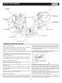
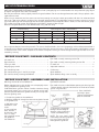
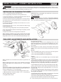
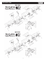
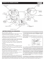
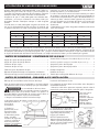
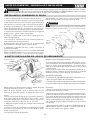
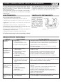
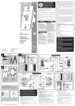
KN 7060
KN 7070
TABLE OF CONTENTS
Specifications ...................................................................... 2
Important safety rules .......................................................... 3
Know your bench grinder ...................................................... 4
Operating instructions ...................................................... 5-10
Maintanance ....................................................................... 11
Troubleshooting .............................................................. 12,13
Exploded view and parts list .......................................... 14,15
Warranty ............................................................................. 16
SPECIFICATIONS
Model # Motor Type: Motor Ratings: Horsepower: Wheel Diameter: Wheel Width: Arbor Hole: No load Speed: Wheel Grits: KN 7060 Induction 120 V AC, 60 Hz 1/2 HP 6” (150 mm) 3/4” (20 mm) 1/2” (13 mm) 3450 RPM 36 (Coarse) / 60 (Medium) KN 7070
Induction
120 V AC, 60 Hz
3/4HP
8” (200 mm)
1”(25 mm)
5/8” (15.88 mm)
3450 RPM
36 (Coarse) / 60 (Medium)
Important Safety Rules
DANGER
Failure to observe any of the following instructions could
result in severe personal injury to tool user and bystanders or
cause damage to tool and property!
WARNING
Read, understand and observe all instructions in this
manual before using or operating the tool for which it is written
and supplied. Ensure that anyone who is to use the tool has
read and understood the instructions provided.
• Always wear eye protection that complies with a recognized
standard (CSA or ANSI).
• Wear a mask or respirator when dust is generated.
• Keep bystanders out of the work area while operating the
tool.
• WARNING! Always ensure that the work area is clear of any
flammable materials, liquids or gasses, because the use of this
tool may create sparks.
• Tighten grinding wheel lock nuts, securing bolts and all clamps
and guards.
• During each start-up, stand to one side of the grinder and
switch it ‘On’. Let the grinder operate at full speed for approximately one minute so that any undetected flaws or cracks will
become apparent.
• To avoid electric shock, DO NOT use in damp conditions or
expose to rain.
• When fitting a new grinding wheel, always check that the stated maximum RPM meets or exceeds that stated on the grinder.
Also check the new wheel for damage, such as flaws or cracks.
If the wheel appears satisfactory, fit it to the grinder.
• When a new grinding wheel has been fitted, stand to one side
of the grinder and switch it ‘On’. Let the grinder operate at full
speed for approximately one minute so that any undetected
flaws or cracks will become apparent.
• Use only accessories that are recommended by the manufacturer for your model.
• DO NOT attempt to cut anything with the grinding wheel.
• Grounded tools must be plugged into an outlet that has been
properly installed and grounded in accordance with all local
codes and ordinances. Never remove the grounding prong from
the plug or modify it in any way. Do not use adaptor plugs. If in
doubt as to whether the outlet is properly grounded, consult a
qualified electrician.
• Do not use the tool when tired or under the influence of drugs,
alcohol or medication.
• Do not wear loose clothing or jewellery. Keep hair tied back.
• Ensure the power switch is off prior to plugging in the tool.
• Keep guards in place and working properly.
• WARNING! Replace cracked grinding wheels immediately.
• Keep hands clear of grinding wheels.
• Do not overtighten spindle nuts.
• Never reach behind or beneath the grinding wheels.
• Adjust tool rests whenever necessary to maintain a distance
of 1/8” (3.2 mm) from the grinding wheel.
• Unplug from power supply before adjusting or servicing. The
grinding wheels continue to rotate after the tool is switched off.
Always allow wheels to stop before adjusting or servicing.
• Service on these tools should only be performed by an authorized, qualified technician.
KNOW YOUR GRINDER
Pain eye shield
Magnify eye
shield
Spark deflector
Grinding wheel
(60 Grit)
Grinding
wheel (36 Grit)
Tool rest (Right)
Tool rest (Left)
On/Off switch
Bolt-down hole
Water tray
Operating Instructions
an electric cord that has an equipment grounding conductor and a
grounding plug. The plug MUST be plugged into a matching outlet
that is properly installed and grounded in accordance with ALL local codes and ordinances.
DO NOT MODIFY THE PLUG PROVIDED. If it will not fit the outlet, have the proper outlet installed by an electrician.
Before You Start - Safety
• Always wear eye protection that complies with a recognized
standard (for example: ANSI Z87.1) - (CSA or ANSI).
• Wear a mask or respirator when dust is generated.
• Keep bystanders out of the work area while operating the tool.
• WARNING! Always ensure that the work area is clear of any
flammable materials, liquids or gasses, because the use of this
tool may create sparks.
• Do not wear loose clothing or jewellery. Keep hair tied back.
• WARNING! Replace cracked grinding wheels immediately.
• Do not overtighten spindle nuts.
• Adjust tool rests whenever necessary to maintain a distance
of 1/8” (3.2 mm) from the grinding wheel.
• NEVER grind on the side of the wheel. Grind on the face of
the wheel only.
• NEVER apply pressure to the workpiece when the grinding
wheel is cold. Allow the wheel to warm up by applying the workpiece gradually.
• NEVER use the grinder without the wheel guards. Keep
thumbs and fingers away from the wheel.
3- Pronged Plug
Grounding Prong
Properly Grounded
3-Holed Receptacle
Fig. 2
IMPROPER CONNECTION of the equipment grounding conductor can result in increased risk of electric shock. The conductor
with the green insulation (with or without yellow stripes) is the
equipment grounding conductor. If repair or replacement of the
electric cord or plug is necessary, DO NOT connect the equipment grounding conductor to a live terminal.
CHECK with a qualified electrician or service personnel if you do
not completely understand the grounding instructions, or if you
are not sure if the tool is properly grounded.
This tool is intended for use on a circuit that has an outlet that
looks like the one illustrated. The original tool has a grounding plug
that looks like the plug illustrated (Figure 2).
Before You Start – Electrical
In the event of a malfunction or short circuit, grounding provides
the path of least resistance for electrical current, and reduces the
risk of electric shock for the operator. This tool is equipped with
2
Use of Extension Cords
USE ONLY THREE-WIRED EXTENSION CORDS that have 3-pronged plugs and 3-holed outlets that accept the tool’s plug. Repair
or replace damaged or worn cords immediately.
Be sure your extension cord is properly wired and in good condition. Do not use damaged extension cords. Always replace a damaged extension cord.
When using an extension cord, be sure to use one heavy enough to carry the current your product will draw. An undersized cord
will cause a drop in line voltage, resulting in loss of power and overheating. The table below shows the correct size to use according to the cord length and the amperage draw of the tool (specified on the nameplate). When in doubt, use the next heavier gauge.
The smaller the gauge number, the heavier the cord. (AWG = American Wire Gauge).
Minimum Gauge for Extension Cords (AWG) (when using 120 volts only)
Ampere Rating More Than Not more Than 0
6
6
10 10 12 12 16 Total Length of Cord in Feet (meters)
25’ (7.6m) 50’ (15m) 100’ (30.4m) 150’ (45.7m)
18 16 16 14
18 16 14 12
16 16 14 12
14 12 Not Recommended
Use a separate electrical circuit for your tools. This circuit should not be less than a #12 gauge wire, and should be protected with a
15 A time-lag fuse. Before connecting the motor to the power line, ensure the switch is in the OFF position and the electric current
is rated the same as the current stamped on the motor’s nameplate. Running at a lower voltage will damage the motor and is not
covered by warranty.
Before You Start – Package Contents
Eye shield assembly mounting washer D6 ...........................
Eye shield assembly mounting locking washer D6 ...............
Fix work rest ......................................................................
Adjustable work rest ...........................................................
Coolant tray ........................................................................
Spark deflector ...................................................................
Spark deflector fixing screw assembly ................................
Left work rest ....................................................................... 1
Right work rest ..................................................................... 1
Plain eye shield .................................................................... 1
Magnifying eye shield ........................................................... 1
Eye shield fixing knob ........................................................... 2
Eye shield mounting rod – one left, one right
Eye shield assembly mounting bolt M6x30 ........................... 2
2
2
2
2
1
2
2
Before You Start – Assembly and Installation
Mounting the Grinder to the Workbench
Before attempting to use this grinder, it must be properly mounted to a workbench or grinding stand.
CAUTION! Bench grinders vibrate. Grinder movement during
high-speed rotation may cause injury or damage to the workpiece or operator. Mount the grinder securely to a sturdy workbench or grinding stand.
Eye Shield Installation
Eye shields must be installed before operating the bench grinder.
1. Mount the left and right shield rods to the inside of the wheel
guards using hex bolts.
2. Once shield rods
are firmly in place,
Eye shield
slide the shield bracket
mounting arm
Safety eye
onto the shield rod.
shield
1. Position the grinder on the workbench.
2. Mark the workbench through the two mounting holes located
in the grinder base.
3. Drill holes in the
Bolt
workbench at the
flat
marks.
washer
4. Using two long
bolts, washers,
lock-washers and
nuts, as shown
(not supplied), secure
Workbench
the grinder to
Flat washer
the workbench.
Hex nut
Washer Hex
bolt
Adjustable
knob
3. Tighten the carriage bolt,
leaving it loose enough to
allow the safety shield to be
raised and lowered easily.
NOTE: The eye shield should
move freely when being adjusted,
but stay in place when the
locking knob is tightened.
3
Eye shield
Before You Start – Assembly and Installation
WARNING Turn the power off and remove the plug from the outlet before changing the grinding wheels. When turning
the grinder on with a newly installed wheel, DO NOT STAND IN FRONT OF THE GRINDER. Stand to the side and allow
the grinder to run for at least one minute before proceeding to use it.
Installing or Changing the Wheel
1. Use a screwdriver to loosen the wheel cover.
2. Fit an appropriately sized wrench on the spindle hex nut.
3. Loosen the wheel nut in a clockwise direction for the left side and
a counter-clockwise direction for the right side.
4. Remove the outer flange and grinding wheel. To remove the hex
nut, turn the wrench and nut until the wrench is resting on the workbench behind the tool.
5. Inspect the new wheel carefully to ensure there are no cracks,
chips or other damage.
6. Wipe the flange surfaces clean, and install the new wheel, flange
and the spindle hex nut.
7. To install a new grinding wheel, reverse the above procedure.
8. Be sure the grinding wheel and outer flange are properly seated
on the spindle shaft.
9. Replace the wheel cover and reposition the tool rest.
When turning the grinder on with a newly installed wheel, DO NOT
STAND IN FRONT OF THE GRINDER. Stand to the side and allow
the grinder to run for at least one minute before proceeding to use it.
IMPORTANT! Do not overtighten the spindle hex nut, because this
may cause the wheel to crack.
CAUTION
DO NOT INSTALL OR USE A DAMAGED GRINDING
WHEEL. The force of rotation may cause a damaged wheel to fly
apart, and could injure operators or bystanders.
Screw
Inner flange
Grinding wheel
Outer flange
Wheel guard
cover
Nut
Tool Rest Adjustments and Installation
Using Your Bench Grinder
This Bench Grinder is ideal for use in sharpening chisels, axes and
Washer
other wood-cutting tools. It is also useful for repairing tips on screwAdjusting knob
drivers and drill bits or for removing excess metal burrs from pieces
of cut metal.
Tool rest
Carriage
bracket
bolt
With the proper accessories, this tool can be used for cleaning metal
surfaces using a wire brush or for buffing and polishing using a cloth
Pin
wheel.
ON/OFF
Tool
The rocker ON/OFF power switch is located on the front of the grinder.
rest
asembly
1. Press the side marked ON to turn the grinder on.
2. Press the side marked OFF to turn the grinder off.
Washer
Grinding
Star washer
Adjusting
• Adjust the tool rest to accommodate large or unusually shaped
knob
workpieces.
Mount the tool rests to the work rest bracket using the knob and • Always keep the workpiece moving across the face of the grinding
washers.
wheel. Grinding continuously on the same spot on the wheel will cause
Before tightening the knob, adjust the gap between the grinding grooves to be worn into the wheel. The wheel may crack or become
wheel and the work rest to a maximum of 1/8” (3.2 mm). Tighten damaged more easily, and grinding of other objects will be difficult.
securely.
• If the workpiece becomes hot, dip it into the water or oil to cool it.
• Always grind on the face of the wheel (around the diameter), NEVAdjustments
To prevent the workpiece from being pulled and caught between the ER on the sides. Side pressure on grinding wheels can cause cracktool rest and the wheel, readjust the tool rest position whenever nec- ing and damage.
essary to maintain the 1/8” (3.2 mm) distance.
• If the face of the grinding wheel is worn unevenly, becomes grooved,
or is no longer smooth and flat, the wheel should be reshaped with a
1. Loosen, but do not remove, the knob holding the tool rest arm.
dressing tool (not supplied).
2. Slide the tool rest in or out to achieve a 1/8” (3.2 mm) distance
• If the diameter of the grinding wheel is no longer round, the wheel
from the grinding wheel surface.
should be reshaped with a dressing tool or replaced.
3. Re-tighten the lock knob.
• If the surface of the wheel becomes loaded and dull with workpiece
material, the wheel should be cleaned with a dressing tool.
4 • After reshaping, always readjust the tool rests and spark arrestors.
Tool rest (right)
Maintenance
Maintenance Required 1. Check power cord 2. Check wheels for cracks 3. Check moving parts for alignment
and binding issues 4. Dress Grinding Wheels 5. Replace Grinding Wheels
(see manual section for specifics) 6. Clean and vacuum dust from the motor
housing and other grinder parts 7. Replace work-light bulb Frequency
Before each use.
Before each use.
Service beyond recommended maintenance on these tools should
only be performed by an authorized, qualified technician.
COOLANT TRAY
When grinding, metal objects
become heated quickly. It is
important to keep moving the
object back and forth across
the face of the grinding wheel
and to cool the object
frequently using the coolant
tray.
Before each use.
As needed.
As needed.
As needed.
As needed.
Collant tray
Troubleshooting
Service on these tools should only be performed by an authorized, qualified technician.securely.
SYMPTOM
Motor will not start.
PROBABLE CAUSE
1. Low Voltage.
2. Open circuit in moto
or loose connections.
3. Blown fuse or breaker.
CORRECTIVE ACTION
1. Check power source for proper voltage.
2. Inspect all lead connection on motor for loose or open
connections. (Send for Servicing.)
3. Short circuit. (Send for Servicing.)
4. Improper match between tool and circuit, fuse or breaker.
Motor will not
start – fuses or
circuit breakers
tripping or blowing.
1. Short circuit in line,
cord or plug.
2. Short circuit in motor
or loose connections.
3. Incorrect fuses or circuit
breakers in power line.
1. Inspect cord or plug for damaged insulation and shorted wires.
2. Inspect all connections on motor for loose or shorted
terminals and/or worn insulation.
3. Install correct fuses or circuit breakers or switch
tool to an appropriately sized circuit.
Motor overheats.
1. Motor overloaded.
2. Extension cord too long and
of insufficient gauge (weight).
1. Reduce load on motor.
2. Utilize an extension cord of appropriate gauge
and length or plug tool directly into outlet.
Motor stalls
(resulting in blown
fuses or tripped
circuit).
1. Short circuit in motor
or loose connections.
2. Low voltage.
3. Incorrect fuses or circuit
breakers in power line.
4. Motor overload.
1. Inspect connections on motor for loose or shorted
terminals or worn insulation. (Send for Servicing.)
2. Correct low voltage conditions (for example: improper
extension cord length and/or gauge).
3. Install correct fuses or circuit breakers or plug tool into an
appropriate circuit, matched to an appropriate fuse or breaker.
4. Reduce the load on the motor.
Machine slows
when operating.
1. Feed rate too great.
1. Reduce the rate at which the workpiece is fed into
the working area of the tool (grinding wheel).
Wavy condition
on surface of
workpiece.
1. Machine vibrating.
2. Workpiece not being
held firmly.
3. Wheel face uneven.
4. Wheel is too hard.
1. Ensure machine is securely mounted on a solid surface.
2. Use a holding device to firmly retain the workpiece.
3. Dress the grinding wheel.
4. Use softer wheel, or reduce the feed rate.
Lines on surface
of workpiece.
1. Impurity on surface of wheel.
2. Workpiece not being
held tightly.
1. Dress the grinding wheel.
2. Use a holding device to more firmly retain the workpiece.
Burning spots
or cracks in the
workpiece.
1. Improper type of grinding wheel.
2. Improper feed rate.
3. Coolant required.
1. Try wheels with softer bond or coarser grit.
2. Slow down the rate at which the workpiece is fed into the wheel.
3. Introduce coolant.
5
Troubleshooting
SYMPTOM
Wheel dulls quickly,
grit falls off.
PROBABLE CAUSE
1. Feed rate is too aggressive.
2. Wheel is soft.
3. Wheel diameter too small.
4. Bad wheel dressing.
5. Defective wheel bonding.
CORRECTIVE ACTION
1.Decrease feed rate of workpiece into grinding wheel.
2. Select a grinding wheel with a harder bond of material.
3. Replace wheel.
4. Dress the wheel.
5. DO NOT USE – return wheel to point of purchase.
Wheel clogs
and workpiece
shows burn marks.
1. Wheel is too hard.
2. Feed rate is too slow.
3. Bad wheel dressing.
4. Coolant required.
1. Select a grinding wheel with a softer bond of material.
2. Increase the feed rate of the workpiece into the grinding wheel.
3. Dress the wheel.
4. Introduce coolant.
PARTS LIST
Mod: KN 7070
Mod: KN 7060
KEY#
1
2
3
4
5
6
7
8
9
10
11
12
13
14
15
16
17
18
19
20
21
22
23
24
25
26
27
28
29
30
31
32
33
34
35
36
37
38
39
40
41
42
43
44
45
46
47
48
49
50
51
52
53
54
55
56
DESCRIPTION
SPEC.
SCREW (PH) (BLACK)
M5 x 48
LEFT WHEEL COVER
HEX NUT(ZINC COATING)
M12 LEFT
OUTER WHEEL CLAMP
WHITE WHEEL (150 X 20 X 32MM)
120#
SCREW & WASHER ASSY. ZINC COATING
M5 x 10
LEFT WHEEL GUARD ASSY.
SPARK DEFELECTOR
SCREW & WASHER ASSY. (BLACK)
M5 x 10
LEFT WORK REST SUPPORT
BIG FLAT WASHER (BLACK)
5
TOOTHED LOCK WASHER (BLACK)
5
LOCK NUT
M5
LEFT WORK REST
FLAT WASHER (BLACK)
6
TOOL REST FIXING KNOB
M6 x17
LEFT EYESHIELD MOUNT ROD
STANDARD SPRING WASHER (BLACK)
6
HEX BOLT (BLACK)
M6 x 30
MAGNIFY EYESHIELD ASSY.
EYESHIELD LOCK KNOB
M5 x 14
SCREW (PH)
M4 x 118
FLAT WASHER
4
END CAP
INNER WHEEL CLAMP SCREW & WASHER ASSY. (PH)(ZINC COATING)
M4 x 8
TOOTHED LOCK WASHER (BLACK)
4
WIRE BUSHING
CORD CLIP 6P4 SCREW & WASHER ASSY. (PH) (ZINC COATING)
M4 x 12
BASE
WAVE WASHER (BLACK)
D35
BEARING
6202RZ
STATOR
ROTOR
HEX FLANGE NUT
M4
CORD & PLUG
SWITCH PLATE
RIGHT EYESHIELD MOUNT ROD
EYESHIELD ASSY.
RIGHT WHEEL GUARD ASSY.
WHEEL (150 X 20 X 32MM)
60#
HEX NUT (ZINC COATING)
M12
RIGHT WHEEL COVER
RIGHT WORK REST
RIGHT WORK REST SUPPORT
COOLANT TRAY
HEX FLANGE NUT (BLACK)
M5
CARRIAGE BOLT BLACK
M5 x 51
SCREW (PH) BLACK
M4 x 8
SCREW & WASHER ASSY. (PH) (ZINC COATING)
M6 x 18
CAPACITOR 4uF/450V
SWITCH
COOLANT TRAY CLIP
BASE COVER
RUBBER FOOT
QTY
KEY#
4
1
1
2
1
6
1
2
4
1
2
2
2
1
4
2
1
2
2
1
2
4
4
2
2
3
2
1
1
4
1
1
2
1
1
4
1
1
1
1
1
1
1
1
1
1
1
4
2
4
2
1
1
1
1
4
1
2
3
4
5
6
7
8
9
10
11
12
13
14
15
16
17
18
19
20
21
22
23
24
25
26
27
28
29
30
31
32
33
34
35
36
37
38
39
40
41
42
43
44
45
46
47
48
49
50
51
52
53
54
55
56
57
6
DESCRIPTION
SPEC.
SCREW (PH) (BLACK)
M5 x 48
LEFT WHEEL COVER
HEX NUT(ZINC COATING)
M16 LEFT
OUTER WHEEL CLAMP
WHITE WHEEL (200 X 25 X 32MM)
120#
SCREW & WASHER ASSY. (PH) ZINC COATING
M5 x 10
LEFT WHEEL GUARD ASSY.
SPARK DEFELECTOR
SCREW & WASHER ASSY. (PH) (BLACK)
M5 x 10
LEFT WORK REST SUPPORT
BIG FLAT WASHER (BLACK)
5
TOOTHED LOCK WASHER (BLACK)
5
LOCK NUT
M5
LEFT WORK REST
FLAT WASHER (BLACK)
6
TOOL REST FIXING KNOB
M6 x 17
LEFT EYESHIELD MOUNT ROD
STANDARD SPRING WASHER (BLACK)
_6
HEX BOLT (BLACK)
M6 x 30
MAGNIFY EYESHIELD ASSY.
EYESHIELD LOCK KNOB
M5 x 14
SCREW (PH)
M5 x 155
FLAT WASHER
5
END CAP
INNER WHEEL CLAMP SCREW & WASHER ASSY. (PH) ZINC COATING
M4 x 8
TOOTHED LOCK WASHER (BLACK)
4
WIRE BUSHING
CORD CLIP 6P4
BASE
SWITCH PLATE
WAVE WASHER (BLACK)
D40
BEARING
6203RZ
STATOR
ROTOR
HEX FLANGE NUT
M5
CORD & PLUG
SCREW (PH) BLACK
M4 x 8
RIGHT EYESHIELD MOUNT ROD
EYESHIELD ASSY.
RIGHT WHEEL GUARD ASSY.
WHEEL (200 X 25 X 32MM)
60#
HEX NUT (ZINC COATING)
M16
RIGHT WHEEL COVER
RIGHT WORK REST
RIGHT WORK REST SUPPORT
COOLANT TRAY
HEX FLANGE NUT (BLACK)
M5
CARRIAGE BOLT BLACK
M5 x 51
STANDARD SPRING WASHER (ZINC COATING)
D8
HEX BOLT(ZINC COATING)
M8 x 20
CAPACITOR 10uF/450V
SWITCH
COOLANT TRAY CLIP
BASE COVER
RUBBER FOOT
SCREW & WASHER ASSY. (PH) (ZINC COATING)
M5 x 16
QTY
4
1
1
2
1
6
1
2
4
1
2
2
2
1
4
2
1
2
2
1
2
4
4
2
2
3
2
1
1
1
1
1
2
1
1
4
1
4
1
1
1
1
1
1
1
1
1
4
2
2
2
1
1
1
1
4
4
EXPLODED VIEW
KN 7060
KN 7070
7
INDICE
Especificaciones .................................................................. 2
Reglas de seguridad importantes ........................................ 3
Conozca su esmeriladora de banco ...................................... 4
Instruciones de operación ................................................ 5-10
Mantenimiento ................................................................... 11
Resolución de problemas ............................................... 12,13
Explosivo y lista de partes ............................................. 14,15
Garantía .............................................................................. 16
SPECIFICATIONS
Modelo # Tipo de motor: Valores de l motor: Caballos de fuerza: Diámetro de rueda: Espesor de rueda: Agujero del eje: Velocidad sin carga: Disco abrasivo: KN 7060 Inducción 120 V AC, 60 Hz 1/2 HP 6” (150 mm) 3/4” (20 mm) 1/2” (13 mm) 3,450 RPM 36 (Aspero) / 60 (Intermedio) KN 7070
Inducción
120 V AC, 60 Hz
3/4HP
8” (200 mm)
1”(25 mm)
5/8” (15.88 mm)
3,450 RPM
36 (Aspero) / 60 (Intermedio)
Reglas Importantes de Seguridad
• Para evitar un shock eléctrico, NO utilice en condiciones
húmedas o expuestas a la lluvia.
• Cuando coloque un nuevo disco abrasivo, verifique siempre
que las RPM máximas indicadas coincidan o sean mayores de
aquellas indicadas en la esmeriladora. También verifique el nuevo disco en caso de daños, ya sea fallas o grietas. Si el disco
luce satisfactoriamente, colóquelo en la esmeriladora.
• Cuando se haya colocado un nuevo disco abrasivo, póngase
de pie al costado de la esmeriladora y enciéndala.
Deje que la esmeriladora opere a velocidad máxima durante
aproximadamente un minuto para que cualquier falla o grieta no
detectada se vuelva visible.
• Utilice únicamente accesorios que sean recomendados por el
fabricante para su modelo.
• NO intente cortar nada con el disco abrasivo.
• Las herramientas con descarga a tierra deben estar enchufadas a un toma corriente que haya sido debidamente instalado y
conectado con la descarga a tierra de acuerdo a todos los códigos y ordenanzas locales. Nunca retire la clavija de descarga
a tierra del enchufe o lo modifique en manera alguna. No utilice
enchufes adaptadores. Si tiene dudas con respecto a si él toma
corriente está adecuadamente conectado con la descarga a
tierra, consulte a un electricista calificado.
• No utilice esta herramienta cuando se encuentre cansado o
bajo la influencia de drogas, alcohol o medicación.
• No utilice ropa suelta o alhajas. Mantenga su cabello recogido.
• Asegúrese de que el interruptor se encuentra en “off” (apagado) antes de enchufar la herramienta.
• ¡Advertencia! Reemplace discos abrasivos agrietados inmediatamente.
• No sobre ajuste las tuercas del eje.
• Ajuste los apoyos de herramienta cuando sea necesario para
mantener una distancia de 1/8” (3. 2 mm) del disco abrasivo.
• El mantenimiento de estas herramientas debería ser realizado
únicamente por un técnico autorizado y calificado.
PELIGRO
El no cumplimiento de alguna de las siguientes instru-cciones podría resultar en daños personales severos para el usuario
de la herramienta y quienes se encuentran en las cercanías o
provocar daños a la herramienta y a otros elementos !
ADVERTENCIA
Lea, comprenda y respete todas las instrucciones en
este manual antes de utilizar u operar la herramienta para la
cual se ha escrito y con la que se ha provisto. Asegúrese de
que todo aquel que vaya a utilizar la herramienta haya leído y
comprendido las instrucciones provistas.
• Siempre utilice protección ocular que cumpla con un estándar reconocido (CSA o ANSI).
• Utilice una máscara o respirador cuando se genere polvo.
• Mantenga a los que se encuentran en la cercanía fuera del
área de trabajo mientras opera la herramienta.
• ¡Advertencia! Asegúrese siempre de que el área de trabajo
esté limpia de materiales inflamables, líquidos o gases dado que
el uso de esta herramienta puede producir chispas.
• Ajuste las tuercas de seguridad del disco abrasivo, asegurando los pernos y todas las abrazaderas y protecciones.
• Durante cada encendido, póngase de pie al costado de la esmeriladora y enciéndala. Deje que la esmeriladora opere a velocidad máxima durante aproximadamente un minuto para que
cualquier falla o grieta no detectada se vuelva visible.
• Mantenga las protecciones en su lugar y funcionando adecuadamente.
• Mantenga sus manos lejos de los discos abrasivos.
• Nunca intente alcanzar por detrás o por debajo de los discos
abrasivos.
• Desenchufe de la fuente de alimentación antes de ajustar o
realizar un mantenimiento. Los discos abrasivos continúan girando luego de que la herramienta es apagada. Permita siempre
que los discos se detengan antes de ajustar o realizar un mantenimiento.
8
Conozca Su Esmeriladora
Protector
ocular
normal
Portector ocular
con lupa
Deflector
de chispa
Disco
abrasivo #60
Disco
abrasivo #36
Apoyo de
herramienta
Apoyo de
herramienta
(izqierdo)
Agujero para perno
Encendido/apagado
On/Off
Bandeja de agua
Instrucciones de Operación
Antes de Comenzar - Seguridad
• Siempre utilice protección ocular que cumpla con un estándar
reconocido (por ejemplo: ANSI Z87.1- CSA o ANSI).
• Utilice una máscara o respirador cuando se genere polvo.
• Mantenga a los que se encuentran en la cercanía fuera del
área de trabajo mientras opera la herramienta.
• ¡Advertencia! Asegúrese siempre de que el área de trabajo
esté limpia de materiales inflamables, líquidos o gases dado que
el uso de esta herramienta puede producir chispas.
• No utilice ropa suelta o alhajas. Mantenga su cabello recogido.
• ¡Advertencia! Reemplace discos abrasivos agrietados inmediatamente.
• No sobre ajuste las tuercas del eje.
• Ajuste los asentamientos de la herramienta cuando sea necesario
para mantener una distancia de 1/8” (3. 2 mm) del disco abrasivo.
• NUNCA esmerile sobre el costado del disco. Esmerile sobre
la cara del disco únicamente.
•NUNCA aplique presión sobre la pieza de trabajo cuando el
disco abrasivo se encuentre frío. Permita que el disco se caliente aplicando la pieza de trabajo gradualmente.
• NUNCA utilice la esmeriladora sin los protectores del disco.
Mantenga los pulgares y los dedos lejos del disco.
Antes de Comenzar - Electricidad
En el caso de un mal funcionamiento o de un cortocircuito, la descarga a tierra provee de una vía de menor resistencia para la corriente eléctrica reduciendo el riesgo de recibir un shock eléctrico
por parte del operador. La herramienta está equipada con un cable
eléctrico que tiene incluido un conductor de descarga a tierra y un 9
enchufe de descarga a tierra. El enchufe DEBE estar conectado
a un toma corriente equivalente que esté debidamente instalado
y posea descarga a tierra de acuerdo con TODOS los códigos y
ordenanzas locales.
NO MODIFIQUE EL ENCHUFE PROVISTO. Si no coincidiera con
el toma corriente, haga que un electricista instale el toma corriente adecuado.
Enchufe de 3 patas
Descarga de tierra
Fig. 2
Toma corriente
adecuadamente
conectado
a tierra de 3 patas
UNA CONEXIÓN INDEBIDA del conductor de descarga a tierra
del equipo puede resultar en un incremento del riesgo de recibir
un shock eléctrico El cable conductor con recubrimiento verde
(con o sin franjas amarillas) es el cable conductor de descarga a
tierra del equipo. Si fuera necesario reemplazar o reparar el cable
eléctrico o el enchufe, no conecte el cable conductor de descarga a tierra del equipo a una terminal con corriente. CORROBORE
con un electricista calificado o con personal de mantenimiento si
no comprende completamente las instrucciones de descarga a
tierra, o si no está seguro de que la herramienta esté debidamente conectada a la tierra.
Esta herramienta está diseñada para ser utilizada dentro de un
circuito que tiene un toma corriente que luce como el de la ilustración. La herramienta original posee un enchufe con descarga a
tierra que luce como el enchufe de la ilustración (figura 2).
Utilización de Cables Prolongadores
UTILICE ÚNICAMENTE PROLONGADOES CON TRES CABLES que tengan enchufes de 3 clavijas y toma corrientes con
3 agujeros que acepten el enchufe de la herramienta. Repare o
reemplace cables desgastados o dañados inmediatamente.
Asegúrese de que su cable prolongador esté cableado adecuadamente y en buenas condiciones. No utilice cables prolongadores dañados. Reemplace siempre un cable alargador
dañado.
Cuando utilice un cable prolongador asegúrese de utilizar uno
que sea lo suficientemente pesado para llevar la corriente que
su producto requerirá. Un cable más pequeño que el necesario
Amperaje
Mayor que No mayor a 0
6
6
10 10 12 12 16 provocará una caída en el voltaje de la línea, resultando en una
pérdida de potencia y un recalentamiento.
La tabla a continuación muestra el tamaño correcto para utilizar
de acuerdo a la longitud del cable y del amperaje requerido por
la herramienta (especificado en la placa de identificación). Cuando tenga dudas, utilice el calibre siguiente más pesado. Cuanto más pequeño sea el número del calibre, más pesado será
el cable. (AWG = American Wire Gauge - Calibre de Cables
Americano).
Calibre Mínimo para Cables Alargadores (AWG) (cuando utilice
120 V únicamente)
Largo Total del Cable en Pies (metros)
25” (7.6 m) 50” (15 m) 100” (30.4 m) 150” (45.7 m)
18 16 16 14
18 16 14 12
16 16 14 12
14 12 No se recomienda
Utilice un circuito eléctrico separado para sus herramientas. Este circuito no debería tener un cable con un calibre inferior a #12, y debería estar protegido por un fusible de retraso temporal de 15 A. Antes de conectar el motor a la corriente eléctrica, asegúrese de que
el interruptor se encuentre en la posición de apagado “OFF” y de que la corriente eléctrica corresponda a la que se encuentra indicada
en la placa de identificación del motor. El funcionamiento a un voltaje menor dañará el motor y no está cubierto por la garantía.
Antes de Comenzar - Contenidos de la Caja
Apoyo de la pieza de trabajo izquierdo .................................. 1
Apoyo de la pieza de trabajo derecho ................................... 1
Protector de ojos simple ...................................................... 1
Protector de ojos con lupa .................................................... 1
Perilla de ajuste del protector de ojos .................................. 2
Soporte del protector de ojos-uno izquierdo, uno derecho
Perno de montaje para el ensamblado del protector de ojos .. 2
Arandela D6 de montaje para el ensamblado del protector de ojos ...
Arandela de seguridad de montaje para el ensamblado del protector de ojos ........
Apoyo de la pieza de trabajo fijo ........................................
Apoyo de la pieza de trabajo ajustable ................................
Bandeja refrigerante ............................................................
Deflector de chispas ..........................................................
Tornillo de ensamblaje del deflector de chispas ...................
2
2
2
2
1
2
2
Antes De Comenzar - Ensamblaje e Instalación
Montaje de la esmeriladora sobre el banco de trabajo
Antes de intentar utilizar esta esmeriladora es necesario montarla
adecuadamente sobre un banco de trabajo o pie para esmeriladora.
PRECAUCION Las esmeriladoras de banco vibran
El movimiento de la esmeriladora durante la rotación a
alta velocidad puede causar heridas o daños a las piezas o al
operador. Monte la esmeriladora de manera segura sobre un
banco de trabajo sólido o un pie para esmeriladora.
1. Ubique la esmeriladora sobre el banco de trabajo.
2. Marque el banco de trabajo a través de los 2 agujeros de
montaje localizados en
la base de la
esmeriladora.
Perno
3. Realice las
perforaciones en el
banco de trabajo
Arandela
sobre las marcas.
plana
4. Utilizando 2 pernos
Banco de trabajo
largos, arandelas,
Arandela
arandelas de seguridad
plana
y tuercas, tal como se
ilustra (no provistos),
asegure la esmeriladora
Tuerca hex
al banco de trabajo.
Instalación del Protector Ocular
Los protectores oculares deben ser instalados antes de operar la
esmeriladora de banco.
1. Monte las varillas de los protectores izquierdo y derecho sobre el
interior de los protectores del disco utilizando pernos hexagonales.
Protector de
seguridad
Brazo de montaje del
protector ocular
Arandela
Perilla
ajustable
Perno hex
3. 3.Ajuste el perno, dejándolo
lo suficientemente suelto como
para permitir que el protector de
seguridad pueda levantarse y
bajarse con facilidad.
NOTA: El protector ocular
debería moverse libremente cuando es ajustado, pero permanecer en su lugar cuando la perilla
de bloqueo es ajustada.
10
2. Una vez que las
varillas de los
protectores se
encuentran colocadas
firmemente, deslice
el soporte del
protector sobre la
varilla del protector.
Protector ocular
Antes De Comenzar - Ensamblaje e Instalación
ADVERTENCIA Apague la herramienta y desenchufe del toma corriente antes de cambiar los discos abrasivos. Cuando
encienda la esmeriladora con un disco recién instalado, NO SE PARE FRENTE A LA ESMERILADORA. Párese a un lado y
permita que la esmeriladora funcione durante por lo menos 1 minuto antes de proceder a utilizarla
Instalando o Cambiando el Disco
1. Utilice un destornillador para aflojar el cobertor del disco.
2. Coloque una llave del tamaño apropiado en la tuerca hexagonal del eje.
3. Afloje la tuerca del disco en la dirección de las agujas del reloj para el
lado izquierdo y en contra de las agujas del reloj para el lado derecho.
4. Remueva el ala exterior y el disco abrasivo. Para remover la
tuerca hexagonal gire la llave y la tuerca hasta que la llave descanse sobre el banco de trabajo por detrás de la herramienta.
5. Inspeccione el nuevo disco cuidadosamente para asegurarse
de que no haya grietas, mellas u otros daños.
6. Limpie la superficie del ala e instale el nuevo disco, ala y
tuerca hexagonal del eje.
7. Para instalar un nuevo disco abrasivo, realice el proceso estricto anteriormente de manera inversa.
¡IMPORTANTE! No sobre ajuste la tuerca hexagonal del eje
puesto que esto puede causar que se fisure el disco.
CAUTION
NO INSTALE O UTILICE DISCOS ABRASIVOS USADOS O DAÑADOS. La fuerza de rotación puede causar que un disco dañado salga despedido pudiendo herir al operador o a quienes se encuentren en las cercanías.
Tornillo
Asiento anterior
Disco abrasivo
Asiento exterior
Tuerca
cubierta
protectora
del disco
8. Asegúrese de que el disco abrasivo y el ala exterior estén
adecuadamente asentados sobre la columna del eje.
9. Reemplace la cobertura del disco y vuelva a posicionar el
apoyo de herramienta.
Cuando encienda la esmeriladora con un disco recién instalado, NO SE PARE
FRENTE A LA ESMERILADORA. Párese a un lado y permita que la esmeriladora funcione durante por lo menos 1 minuto antes de proceder a utilizarla.
Ajuste e Instalación del Apoyo de Herramienta.
Apoyo de herramienta
Arandela
Perilla de ajuste
Soporte
del
descanso
de herramienta
Perno
Punta
Ensamblaje
del descanso
de herramienta
Arandela
Arandela
Perilla de estrella
ajuste
Monte el descanso de herramienta sobre el soporte del apoyo
de trabajo utilizando la perilla y las arandelas.
Antes de apretar la perilla, ajuste la distancia entre el disco
abrasivo y el apoyo del trabajo a un máximo de 1/8 (3,2 mm).
Ajustes
Para evitar que la pieza de trabajo sea succionada y quede atrapada entre el apoyo de la herramienta el disco, vuelva a ajustar
la posición del apoyo de la herramienta siempre que sea necesario para mantener una distancia de 1/8” (3,2 mm).
1. Afloje pero no quite la perilla que sostiene el brazo del apoyo
de herramienta.
2. Deslice el apoyo de herramienta hacia adentro o hacia afuera
para alcanzar una distancia de 1/8” (3,2 mm) desde la superficie del disco abrasivo.
3. Re-ajuste de la perilla de seguridad.
Utilización de Su Esmeriladora de Banco
Esta esmeriladora de banco es ideal para afilar cinceles, hachas,
y otras herramientas de cortado de manera. También es útil para
reparar las puntas de los destornilladores y las mechas de taladros o para remover rebabas metálicas excesivas de una pieza
o metal cortado.
Con los accesorios adecuados, esta herramienta puede ser utilizada para limpiar superficies de metal utilizando un cepillo de
alambre o para lustrar y pulir utilizando un disco de tela.
ENCENDIDO/APAGADO
El interruptor de ENCENDIDO/APAGADO (ON/OFF) se encuentra en la parte frontal de la esmeriladora.
1. Presione sobre el lado marcado ON para encender la esmeriladora.
2. Presione sobre el lado marcado OFF para apagar la esmeriladora.
Esmerilado
• Ajuste el apoyo de herramienta para acomodar piezas de trabajo grandes o de formas inusuales
• Mantenga siempre a la pieza de trabajo en movimiento a lo largo de la cara del disco abrasivo. El esmerilado continuo sobre la
misma parte del disco abrasivo causará que se formen surcos en
el disco abrasivo. El disco puede quebrarse o dañarse más fácilmente, y el esmerilado de otros objetos resultará dificultoso.
• Si la pieza de trabajo se calienta, introdúzcala en agua o aceite
para enfriarla.
• Siempre esmerile sobre la cara de la rueda (alrededor del diámetro), NUNCA sobre los costados. La presión sobre los discos abrasivos puede causar grietas y daños.
11
Ajuste e Instalación del Apoyo de Herramienta.
• Si la cara del disco abrasivo se desgasta de manera despareja, comienza a tener surcos, o ya no es suave y plana, el disco
debería ser devuelto a su forma original con una herramienta
rectificadora (no provista).
• Si el diámetro del disco abrasivo ha dejado de ser redondo, el
disco deberá ser rectificado con una herramienta rectificadora
o reemplazado.
• Si la superficie del disco se carga con piezas de material, el
disco deberá ser limpiado con una herramienta rectificadora.
• Luego de la rectificación es necesario siempre volver a ajustar
el apoyo de la herramienta y los deflectores de chispas.
BANDEJA DE ENFRIAMIENTO
MANTENIMIENTO.
Frecuencia Requerida de Mantenimiento
1. Verifique el cable de alimentación antes de cada uso.
2. Verifique que no haya grietas en los discos antes de cada uso.
3. Verifique las partes móviles en su alineación y encastre antes
de cada uso.
4. Rectifique los discos abrasivos si fuera necesario.
5. Reemplace los discos abrasivos (ver la sección del manual
para las especificaciones) si fuera necesario.
6. Limpie y aspire el polvo de la caja del motor y otras partes de
la esmeriladora si fuera necesario.
7. Reemplace la lámpara de trabajo si fuera necesario
• El mantenimiento que exceda estas recomendaciones debería
ser realizado únicamente por un técnico autorizado y calificado.
Cuando son esmerilados,
los objetos de metal se
calientan
rápidamente.
Es importante mantener
al objeto en movimiento
hacia atrás y adelante
sobre la cara del disco
abrasivo y enfriar el objeto frecuentemente utilizando una bandeja de
enfriamiento.
Collant tray
RESOLUCIÓN DE PROBLEMAS
SÍNTOMA
El motor no
enciende.
CAUSA PROBABLE
1. Bajo voltaje.
2. Circuito abierto en
el motor o conexiones flojas.
3. Fusible o interruptor quemado
ACCIÓN CORRECTIVA
1. Verifique la fuente de alimentación para un voltaje apropiado.
2. Inspeccione todas las conexiones de plomo en el motor en busca
de correcciones sueltas o abiertas (Envíe al servicio técnico).
3. cortocircuito (envíe al servicio técnico.)
4. Falta de correspondencia entre la herramienta y el circuito
o fusible o interruptor.
El motor no
enciende posibles
interruptores
desconectados
o quemados.
1. Cortocircuito en la línea,
cable o enchufe.
2. Cortocircuito en el motor o
conexiones flojas.
3. Fusibles o interruptores
incorrecectos en la línea de
alimentación.
1. Inspeccione el cable o enchufe en busca de aislación dañada
o cables en corto.
2. Inspeccione todas las conexiones del motor en busca de
terminales en corto o flojas y o aislamiento desgastado.
3. Instale los fusibles o interruptores correctos o cambie
la herramienta hacia un circuito de dimensiones apropiadas.
El motor recalienta.
1. Motor sobrecargado.
2. Cable de extensión demasiado
largo y de calibre insuficiente
(peso).
1. Reduzca la carga del motor.
2. Utilice un cable alargador de calibre y largo apropiado o enchufe
directamente la herramienta al toma corriente.
El motor se detiene
(resultando en
fusibles quemados
o circuitos
desconectados).
1. Cortocircuito en el motor o
conexiones flojas.
2. Bajo voltaje.
3. Fusibles o interruptores
incorrectos en la línea de
alimentación.
4. Motor sobrecargado.
1. Inspeccione las conexiones del motor en busca de terminales
en corto o flojas y o aislamiento desgastado. (Envíe al servicio
técnico).
2. Corrija las condiciones de bajo voltaje (por ejemplo: cable
alargador de largo y o calibre incorrectos).
3. Instale los fusiles o interruptores correctos o enchufe la
herramienta a un circuito apropiado, que corresponda a un
fusible o interruptor apropiado.
4. Reduzca la carga del motor.
1. Velocidad de alimentación
La máquina se
demasiado rápida.
ralenta cuando se la
opera.
1. Reduzca el grado con el cual la pieza de trabajo es alimentada
al área de trabajo de la herramienta (disco abrasivo).
12
RESOLUCIÓN DE PROBLEMAS
SÍNTOMA
Características
ondulantes sobre
la superficie de la
pieza de trabajo.
CAUSA PROBABLE
1. La máquina vibra.
2. La pieza de trabajo no está
siendo sujetada firmemente.
3. Cara del disco despareja.
4. El disco es demasiado duro.
ACCIÓN CORRECTIVA
1. Asegúrese de que la máquina esté montada de manera
segura sobre una superficie sólida.
2. Utilice un elemento sujetador para retener con firmeza
a la pieza de trabajo.
3. Rectifique el disco abrasivo.
4. Utilice un disco más blando o reduzca el ritmo de alimentación.
Líneas sobre la
superficie de la
pieza de trabajo.
1. Impurezas sobre la superficie
del disco.
2. La pieza de trabajo no está
siendo sujetada firmemente.
1. Rectifique el disco abrasivo.
2. Utilice un elemento sujetador para retener con firmeza
a la pieza de trabajo
Partes quemadas o
grietas en la
pieza de trabajo.
1. Disco abrasivo de tipo
incorrecto.
2. Ritmo de alimentación
incorrecto.
3. Se requiere enfriamiento.
1. Pruebe con discos con pegamentos más blandos o con
desgastantes más gruesos.
2. Reduzca el ritmo con el cual la pieza de trabajo es
alimentada en el disco.
3. Introduzca refrigerante
El disco pierde el
1. Velocidad de alimentación
demasiado agresiva.
filo rápidamente,
el material
2. El disco es blando.
desgastante se cae.
3. El Diámetro del disco es
demasiado pequeño.
4. Mal rectificado de disco.
5. Aglutinador del disco
defectuoso.
El disco se traba y
la pieza de trabajo
muestra marcas de
quemado.
1. El disco es demasiado duro.
2. Velocidad de alimentación
demasiado lenta.
3. Mal rectificado de disco.
4. Se requiere enfriamiento
1. Reduzca el ritmo de alimentación de la pieza de trabajo
en el disco abrasivo.
2. Seleccione un disco abrasivo con un material aglutinador
más duro.
3. Reemplace el disco.
4. Rectifique el disco abrasivo.
5. NO UTILICE - devuelva el disco al punto de venta.
1. Seleccione un disco abrasivo con un material aglutinador
más blando.
2. Incremente el ritmo de alimentación de la pieza de trabajo
en el disco abrasivo.
3. Rectifique el disco abrasivo.
4. Introduzca refrigerante.
13
LISTAS DE PARTES
Mod: KN 7060
No.
1
2
3
4
5
6
7
8
9
10
11
12
13
14
15
16
17
18
19
20
21
22
23
24
25
26
27
28
29
30
31
32
33
34
35
36
37
38
39
40
41
42
43
44
45
46
47
48
49
50
51
52
53
54
55
56
DESCRIPCION
Mod: KN 7070
ESPECIFICACION CANT.
TORNILLO
M5 x 48
CUBIERTA DE RUEDA IZQUIERDA
TUERCA
M12 IZQ
PRENSA EXTERNA DE RUEDA
RUEDA ESMERIL (150 X 20 X 32 MM)
120#
TORNILLO Y RONDANA
M5 x 10
GUARDA DE RUEDA IZQUIERDA
DEFLECTOR DE CHISPAS
TORNILLO Y RONDANA
M5 x 10
SOPORTE DE DESCANSO DE PIEZA DE TRABAJO IZQUIERDO
RONDANA
5
RONDANA DENTADA
5
TUERCA
M5
DESCANSO DE PIEZA DE TRABAJO IZQUIERDO
RONDANA
6
PERILLA DE AJUSTE DESCANSO DE PIEZA DE TRABAJO IZQUIERDO M6 x 17
VARILLA DE PROTECTOR OCULAR IZQUIERDO
RONDANA DE PRESION
6
TORNILLO
M6 x 30
PROTECTOR OCULAR
PERILLA ASEGURADORA DE PROTECTORE OCULAR
M5 x 14
TORNILLO
M4 x 118
RONDANA
4
TAPON
PRENSA INTERNA DE RUEDA
TORNILLO Y RONDANA
M4 x 8
RONDANA DENTADA
4
ESPACIADOR
PRESILLA DE CABLE
TORNILLO Y RONDANA
M4 x 12
BASE
RONDANA ONDULADA
D35
BALERO 6202RZ
ESTATOR
ROTOR
TUERCA CON PESTAÑA
M4
CABLE Y CLAVIJA
PLACA DEL INTERRUPTOR
VARILLA DE PROTECTOR OCULAR DERECHO
PROTECTOR OCULAR
GUARDA DE RUEDA DERECHA
RUEDA ESMERIL (150 X 20 X 32 MM)
60#
TUERCA
M12
CUBIERTA DE RUEDA DERECHA
DESCANSO DE PIEZA DE TRABAJO DERECHO
SOPORTE DE DESCANSO DE PIEZA DE TRABAJO DERECHO
BANDEJA DE ENFRIAMIENTO
TUERCA CON PESTAÑA
M5
TORNILLO
M5 x 51
TORNILLO
M4 x 8
TORNILLO Y RONDANA
M6 x 18
CAPACITOR 4uF/450V
INTERRUPTOR
PRESILLA DE LA BANDEJA DE ENFRIAMIENTO
CUBIERTA DE LA BASE
PATAS DE HULE
No.
1
2
3
4
5
6
7
8
9
10
11
12
13
14
15
16
17
18
19
20
21
22
23
24
25
26
27
28
29
30
31
32
33
34
35
36
37
38
39
40
41
42
43
44
45
46
47
48
49
50
51
52
53
54
55
56
57
4
1
1
2
1
6
1
2
4
1
2
2
2
1
4
2
1
2
2
1
2
4
4
2
2
3
2
1
1
4
1
1
2
1
1
4
1
1
1
1
1
1
1
1
1
1
1
4
2
4
2
1
1
1
1
4
14
DESCRIPCION
ESPECIFICACION CANT.
TORNILLO
M5 x 48
CUBIERTA DE RUEDA IZQUIERDA
TUERCA
M16 LEFT
PRENSA EXTERNA DE RUEDA
RUEDA ESMERIL (200 X 25 X 32MM)
120#
TORNILLO Y RONDANA
M5 x 10
GUARDA DE RUEDA IZQUIERDA
DEFLECTOR DE CHISPAS
TORNILLO Y RONDANA
M5 x 10
SOPORTE DE DESCANSO DE PIEZA DE TRABAJO IZQUIERDO
RONDANA
5
RONDANA DENTADA
5
TUERCA
M5
DESCANSO DE PIEZA DE TRABAJO IZQUIERDO
RONDANA
6
PERILLA DE AJUSTE DESCANSO DE PIEZA DE TRABAJO IZQUIERDO M6 x 17
VARILLA DE PROTECTOR OCULAR IZQUIERDO
RONDANA DE PRESION
6
TORNILLO
M6 x 30
PROTECTOR OCULAR
PERILLA ASEGURADORA DE PROTECTORE OCULAR
M5 x 14
TORNILLO
M5 x 155
RONDANA
5
TAPON
PRENSA INTERNA DE RUEDA
TORNILLO Y RONDANA
M4 x 8
RONDANA DENTADA
4
ESPACIADOR
PRESILLA DE CABLE
BASE
PLACA DEL INTERRUPTOR
RONDANA ONDULADA
D40
BALERO 6203RZ
ESTATOR
ROTOR
TUERCA CON PESTAÑA
M5
CABLE Y CLAVIJA
TORNILLO
M4 x 8
VARILLA DE PROTECTOR OCULAR DERECHO
PROTECTOR OCULAR
GUARDA DE RUEDA DERECHA
RUEDA ESMERIL (200X25X32MM)
60 #
TUERCA
M16
CUBIERTA DE RUEDA DERECHA
DESCANSO DE PIEZA DE TRABAJO DERECHO
SOPORTE DE DESCANSO DE PIEZA DE TRABAJO DERECHO
BANDEJA DE ENFRIAMIENTO
TUERCA CON PESTAÑA
M5
TORNILLO
M5 x 51
RONDANA DE RESORTE
D8
TORNILLO
M8 x 20
CAPACITOR 10uF/450V
INTERRUPTOR
PRESILLA DE LA BANDEJA DE ENFRIAMIENTO
CUBIERTA DE LA BASE
PATAS DE HULE
TORNILLO Y RONDANA
M5 x 16
4
1
1
2
1
6
1
2
4
1
2
2
2
1
4
2
1
2
2
1
2
4
4
2
2
3
2
1
1
1
1
1
2
1
1
4
1
4
1
1
1
1
1
1
1
1
1
4
2
2
2
1
1
1
1
4
4
www.knova.com.mx