1
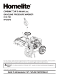
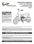
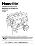
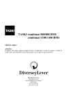
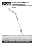
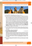
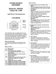
ASSEMBLY GUIDE GUÍA DE ARMADO WR200 / HEAT / WARRIOR / CARBON / MINI BAJA MB200 Follow all instructions when assembling this mini bike. If any parts are damaged or missing, those parts must be replaced before proceeding. WARNING: To reduce the risk of injury, you must read and understand this assembly guide before attempting to assemble this product. SAVE THIS GUIDE FOR FUTURE REFERENCE Siga todas las instrucciones al armar este mini motocicleta. Si falta alguna pieza o hay piezas dañadas, dichas piezas deben reemplazarse antes de proceder a utilizar el producto. ADVERTENCIA: Para reducir el riesgo de lesiones, debe leer y comprender esta guía de armado antes de intentar armar este producto. GUARDE ESTE MANUAL PARA FUTURAS CONSULTAS TABLE OF CONTENTS Rules for Safe Assembly................................................................................................................................................... 2 Symbols............................................................................................................................................................................. 3 Tools Needed..................................................................................................................................................................... 3 Unpacking.......................................................................................................................................................................... 4 Loose Parts List................................................................................................................................................................. 5 Assembly........................................................................................................................................................................6-8 Final Preparation............................................................................................................................................................... 9 RULES FOR SAFE ASSEMBLY WARNING: Strictly adhere to all torque wrench tightening specifications. Failure to do so could cause serious personal injury. All information, illustrations, photographs and specifications contained in this manual are based on the latest product information available at the time of publication. Due to improvements or other changes, there may be some discrepancies in this manual. We reserve the right to make product changes at any time, without notice and without incurring any obligation to make the same or similar changes to the vehicle previously built or sold. © 2010 Baja, Inc. All Rights Reserved. Any person attempting to assemble this product must have proper training and experience. Read this manual carefully and follow all assembly procedures as described. In addition to completing all the items in this manual, mechanic must read and complete the Dealer portion of the Pre-Delivery Inspection Checklist. All assembly must be completed with the unit on a level surface. 2 — English SYMBOLS The following signal words and meanings are intended to explain the levels of risk associated with this product. SYMBOL SIGNAL MEANING DANGER: Indicates an imminently hazardous situation, which, if not avoided, will result in death or serious injury. WARNING: Indicates a potentially hazardous situation, which, if not avoided, could result in death or serious injury. CAUTION: Indicates a potentially hazardous situation, which, if not avoided, may result in minor or moderate injury. CAUTION: (Without Safety Alert Symbol) Indicates a situation that may result in property damage. Some of the following symbols may be used on this product. Please study them and learn their meaning for safe operation of this product. SYMBOL NAME Safety Alert EXPLANATION Indicates a potential personal injury hazard. TOOLS NEEDED The following tools (not included or drawn to scale) are needed for assembly: 20 0 30 40 50 TORQUE WRENCH METRIC HAND TOOLS 3 — English © 2010 Baja, Inc. All Rights Reserved. UNPACKING NOTE: Having two people available will make the assembly process easier, even if using an overhead hoist. n Carefully cut packing straps and remove cardboard carton from metal frame. WARNING: Do not stand at the front or the rear of the mini bike while the straps are being cut. Keep the carton level while lifting and do not allow it to tip forward or backward. Failure to follow these instructions could result in serious personal injury. nRemove manufacturer’s statement of origin, assembly guide, operator’s manual, and assembly hardware. nRemove all bolts, brackets, and ties that attach the metal shipping crate to the mini bike. See figure below. nWith a person on each side, carefully lift shipping crate off the mini bike and set aside. NOTE: If a second person is unavailable, use an overhead hoist to lift and remove the metal frame. © 2010 Baja, Inc. All Rights Reserved. WARNING: Carefully support the crate at all times during the removal process. Allowing the crate to drop could cause serious injury and/or damage the mini bike. nRemove and set aside all packaging and wrap from unit and parts. Do not discard the packing material until you have carefully inspected and satisfactorily operated the product. WARNING: Do not use this product if any parts on the Loose Parts List are already assembled to your product when you unpack it. Parts on this list are not assembled to the product by the manufacturer and require customer installation. Use of a product that may have been improperly assembled could result in serious personal injury. n Inspect the product carefully to make sure no breakage or damage occurred during shipping. nIf any parts are damaged or missing, please call 1-888-863-2252 for assistance. 4 — English LOOSE PARTS LIST Key No. 1 2 3 1. Description Qty. Headlight Hardware Bolt (M6 x 55 mm)............................................ 1 Nut (M6)............................................................ 1 Rear Fender Hardware Fender.............................................................. 1 Bolt (M6 x 25 mm)............................................ 4 Nut (M6)............................................................ 4 Tool Kit.................................................................. 1 Assembly Guide (Not Shown)............................... 1 Operator’s Manual (Not Shown)............................ 1 WARNING: If any parts are damaged or missing do not assemble this product until the parts are replaced with new original manufacturer’s parts or their equivalent. Assembly of this product with damaged, missing, or incorrect parts could result in serious personal injury. 2. 3. 5 — English © 2010 Baja, Inc. All Rights Reserved. ASSEMBLY INSTALLING HANDLEBAR WARNING: Strictly adhere to all torque wrench tightening specifications. Failure to do so could cause serious personal injury. WARNING: Do not attempt to modify this product or create accessories not recommended for use with this product. Any such alteration or modification is misuse and could result in a hazardous condition leading to possible serious personal injury. Remove cinch nuts and washers with rubber grommets from steering bracket. Attach handlebar assembly to steering bracket using one washer and grommet on top of the bracket and one washer and grommet under the bracket. Install cinch nut and tighten securely. Torque to 33 ft.lbs. (45 Nm). RUBBER GROMMET WARNING: To prevent accidental starting that could cause serious personal injury, always disconnect the engine spark plug wire from the spark plug when assembling parts. INSTALLING HEADLIGHT Align holes in headlight with holes in headlight bracket. Install bolt and nut; tighten securely. WASHER CINCH NUT NUT BOLT Verify allen head bolts on top handlebar clamp are tightened securely. Torque to 20 ft.lbs. (27 Nm). ALLEN HEAD BOLTS © 2010 Baja, Inc. All Rights Reserved. 6 — English ASSEMBLY INSTALLING REAR FENDER TIGHTEN JACKSHAFT NUT Lift rear fender into position and align holes in fender with holes in fender brackets. Install bolts and nuts. Tighten securely. Torque to 7 ft.lbs. (9.5 Nm). Tighten jackshaft nut. Torque to 60-80 ft.lbs. (81.3-108.5 Nm). JACKSHAFT NUT FENDER NUT TIGHTEN FRONT SHOCK BOLTS Tighten front shock bolts securely. Torque to 35 ft.lbs. (47.5 Nm). SHOCK BOLTS BOLT VERIFY TIRE PRESSURE Check the air pressure of the tires and inflate as needed to the proper amount. NOTE: Tire pressure should only be measured or adjusted when tires are cold. Recommended Pressure 12 psi (82.7 kPa) WARNING: Check the tire pressure carefully while inflating. Too much air in the tire could cause the tire to burst, causing serious personal injury. WARNING: Maintaining correct air pressure in the tires is very important. Too little pressure could allow the tire to rotate off the wheel rim. Too much pressure could cause the tire to burst. Failure to maintain correct air pressure in the tires could cause problems with vehicle operation and stability, causing serious personal injury. 7 — English © 2010 Baja, Inc. All Rights Reserved. ASSEMBLY CHECKING/CHANGING ENGINE LUBRICANT Always use a 4-stroke motor lubricant that meets or exceeds the requirements for API service classification SJ. ENGINE LUBRICANT SAE 10W-30 SAE 20W-40 SAE 10W-50 SAE 15W-40 TEMP. °C -30-20-10 0 10 20 30 40 °F -22-4 1432506886104 To check lubricant level: Park vehicle on level ground and lower side stand. Start the engine and allow it to run for 3 to 5 minutes. Turn the engine off and allow to cool for at least 3 minutes. Unscrew the oil cap/dipstick and remove. Wipe dipstick clean and re-seat in hole, but do not rethread. Hold the mini bike upright, remove the dipstick, and inspect the lubricant level. Level should be between the minimum and maximum marks on the dipstick. If lubricant is below minimum mark on dipstick, add lubricant until level falls between minimum and maximum marks on the dipstick. To change engine lubricant: Lubricant should be changed while the engine lubricant is still warm, but not hot. This allows the lubricant to drain quickly and completely. Park vehicle on level ground and lower side stand. Start the engine and allow it to run for 3 to 5 minutes. Turn the engine off and allow to cool for at least 3 minutes. Remove oil cap/dipstick. Place a container underneath the oil drainage bolt to collect used lubricant as it drains. Unscrew the oil drainage bolt and remove the bolt and washer. Allow lubricant to drain completely. Inspect sealing washer and replace if damaged. NOTE: This should be replaced at least every other time the lubricant is changed. Reinstall washer and oil drainage bolt. Torque oil drainage bolt to 18 ft.lbs. (24 Nm) Fill crankcase with 0.50 qt. (0.47 l) SAE15W40 lubricant. Reinstall the oil cap/dipstick. Start the engine and allow it to run for 3 to 5 minutes. Turn the engine off and allow to cool for at least 3 minutes. Hold the mini bike upright and recheck the lubricant level. Make sure there are no leaks. NOTE: Used lubricant should be disposed of at an approved disposal site. See your local oil retailer for more information. CAUTION: Attempting to start the engine before it has been properly filled with lubricant will result in equipment failure. © 2010 Baja, Inc. All Rights Reserved. 8 — English FINAL PREPARATION VERIFY FLUID LEVELS All fluids except fuel and appropriate engine lubricant are filled at the factory. However, before attempting to operate the unit, you should verify the correct levels of all fluids. When checking fluid levels, make sure the unit is on a level surface and the engine is off. COMPLETE PRE-DELIVERY INSPECTION CHECKLIST Verify that all items on the Pre-Delivery Inspection Checklist have been completed as required. Keep this list for delivery to the purchaser of this product. ADD GASOLINE Add a small amount of gasoline to the unit for testing purposes. Always use unleaded gasoline with a pump octane rating of 87 or higher. Never use old, stale, or contaminated gasoline, and do not use an oil/gas mixture. Do not allow dirt or water into the fuel tank. Ethanol. Gasoline containing up to 10% ethanol by volume (commonly referred to as E10) is acceptable. E85 is not. 9 — English © 2010 Baja, Inc. All Rights Reserved. ÍNDICE DE CONTENIDO Reglas para un armado seguro..............................................................................................................................................................2 Símbolos.................................................................................................................................................................................................3 Herramientas necesarias........................................................................................................................................................................3 Cómo retirar el empaque........................................................................................................................................................................4 Lista de piezas sueltas............................................................................................................................................................................5 Armado............................................................................................................................................................................................... 6-8 Preparación final.....................................................................................................................................................................................9 REGLAS PARA UN ARMADO SEGURO ADVERTENCIA: Cumpla estrictamente todas las especificaciones de ajuste con la llave dinamométrica. La inobservancia de esta advertencia podría causar lesiones personales graves. Toda la información, las ilustraciones, las fotografías y las especificaciones que contiene este manual se basan en la información más reciente sobre el producto disponible al momento de la publicación. Debido a las mejoras u otros cambios, puede haber algunas discrepancias en este manual. Nos reservamos el derecho de efectuar cambios en el producto en cualquier momento, sin previo aviso y sin incurrir en obligación alguna de efectuar dichos cambios o cambios similares en el vehículo previamente fabricado o vendido. © 2010 Baja, Inc. Todos los derechos reservados. Cualquier persona que intente armar este producto debe contar con la capacitación y la experiencia adecuadas. Lea este manual detenidamente y siga todos los procedimientos de armado, según se describen. Además de cumplir con todos los puntos incluidos en este manual, el mecánico debe leer y completar la sección para el Concesonario que forma parte de la Lista de verificación de inspección preentrega. La totalidad del armado debe llevarse a cabo con la unidad apoyada sobre una superficie nivelada. 2 — Español SÍMBOLOS Las siguientes palabras y significados de las señales tienen como objetivo explicar los niveles de riesgo asociados con este producto. SÍMBOLO SEÑAL SIGNIFICADO PELIGRO: Indica una situación de riesgo inminente que, si no se evita, provocará la muerte o lesiones graves. ADVERTENCIA: Indica una situación de riesgo potencial que, si no se evita, podría provocar la muerte o lesiones graves PRECAUCIÓN: Indica una situación de riesgo potencial que, si no se evita, puede provocar lesiones menores o moderadas. PRECAUCIÓN: (Sin el símbolo de alerta de seguridad) Indica una situación que puede provocar daños a los bienes. Es posible que algunos de los siguientes símbolos se usen en este producto. Estúdielos y aprenda sus significados para operar este producto con seguridad. SÍMBOLO NOMBRE EXPLICACIÓN Indica un peligro posible de lesiones personales. Alerta de seguridad HERRAMIENTAS NECESARIAS Las siguientes herramientas (no incluidas o dibujadas a escala) son necesarias para el armado y la alineación: 20 0 30 40 50 LLAVE DINAMOMÉTRICA HERRAMIENTA MANUAL MÉTRICA 3 — Español © 2010 Baja, Inc. Todos los derechos reservados. CÓMO RETIRAR EL EMPAQUE NOTA: Disponer de dos personas, hará que el proceso de armado sea más fácil, incluso si se utiliza un equipo de elevación. n Corte cuidadosamente las correas del empaque y retire la caja de cartón. ADVERTENCIA: No se pare en la parte delantera ni trasera del mini motocicleta mientras esté cortando las correas. Mantenga la caja derecha mientras la levanta y no deje que se incline hacia adelante ni hacia atrás. La inobservancia de estas instrucciones podría provocar lesiones personales graves. n Retire la caja que contiene la declaración de origen del fabricante, la guía de armado, el manual del operador y las piezas para realizar el armado. n Retire todos los pernos, los soportes y las ataduras que fijan el embalaje de envío de metal al mini motocicleta. Vea la figura que aparece más abajo. n Con una persona a cada lado, levante con cuidado el embalaje de envío hasta retirarlo del mini motocicleta, y déjelo a un lado. NOTA: Si no hay una segunda persona disponible, use un equipo de elevación para levantar y retirar el armazón de metal. © 2010 Baja, Inc. Todos los derechos reservados. ADVERTENCIA: Sostenga el embalaje con cuidado en todo momento durante el proceso de retirar el armazón. Dejar caer el embalaje podría causar lesiones graves y/o daños al mini motocicleta. nRetire y disponer por completo el material de empaque y el envoltorio de la unidad y de las piezas. No deseche el material de empaque hasta que haya inspeccionado detenidamente el producto y lo haya puesto en funcionamiento de manera satisfactoria. ADVERTENCIA: No utilice este producto si alguna de las piezas incluidas en la Lista de piezas sueltas ya está ensamblada en su producto cuando lo retira del empaque. Las piezas incluidas en esta lista no vienen ensambladas en el producto de fábrica y requieren la instalación por parte del cliente. El uso de un producto que pueda haber sido armado de manera incorrecta podría provocar lesiones personales graves. n Inspeccione el producto detenidamente para asegurarse de que no se hayan producido roturas ni daños durante el envío. n Si falta alguna pieza o hay piezas dañadas, llame al 1-888-863-2252 para obtener ayuda. 4 — Español LISTA DE PIEZAS SUELTAS Ref. Núm. 1 2 3 1. Descripción Cant. Piezas para el faro Perno (M6 x 55 mm)..................................................1 Tuerca (M6)...............................................................1 Piezas del guardabarros traseros) Guardabarros............................................................1 Perno (M6 x 25 mm)..................................................4 Tuerca (M6)..............................................................4 Juego de herramientas...................................................1 Guía de armado (no se muestra)....................................1 Manual del operador (no se muestra).............................1 ADVERTENCIA: Si falta alguna pieza o hay piezas dañadas, no arme este producto hasta que se reemplacen las piezas por piezas nuevas del fabricante original o equivalentes. El armado de este producto con piezas dañadas, faltantes o incorrectas podría provocar lesiones personales graves. 2. 3. 5 — Español © 2010 Baja, Inc. Todos los derechos reservados. ARMADO INSTALACIÓN DEL MANUBRIO ADVERTENCIA: Cumpla estrictamente todas las especificaciones de ajuste con la llave dinamométrica. La inobservancia de esta advertencia podría causar lesiones personales graves. ADVERTENCIA: No intente modificar este producto ni crear accesorios que no estén recomendados para usar con este producto. Dichas alteraciones o modificaciones constituyen un uso indebido y podrían provocar una situación de riesgo que cause posibles lesiones personales graves. Retire las tuercas de remache y las arandelas con anillos protectores de caucho del soporte de dirección. Coloque el armado del manubrio en el soporte de dirección usando una arandela y un anillo protector sobre la parte superior del soporte y una arandela y un anillo protector debajo del soporte. Retire la tuerca de remache y apriete firmemente. Apriete a un par de torsión de 45 Nm (33 pies libra). ANILLO PROTECTORE DE CAUCHO ARANDELA ADVERTENCIA: Para evitar arranques accidentales que podrían causar lesiones personales graves, al armar las piezas desconecte siempre de la bujía el cable de la bujía del motor. INSTALACIÓN DEL FARO TUERCAS DE REMACHE Alinee los orificios en el faro con los orificios en el soporte del faro. Instale el perno y la tuerca; apriete firmemente. TUERCA PERNO Verifique que los pernos de cabeza Allen que se encuentran en la parte superior de la abrazadera del manubrio estén firmemente apretados. Apriete a un par de torsión de 27 Nm (20 pies libra). PERNOS DE CABEZA ALLEN © 2010 Baja, Inc. Todos los derechos reservados. 6 — Español ARMADO INSTALACIÓN DEL GUARDABARROS TRASERO APRIETE LA TUERCA DE EJE SECUNDARIO Levante el guardabarros trasero en posición y alinee los orificios en el guardabarros con los orificios en los soportes del guardabarros. Apriete la tuerca de eje secundario Apriete a un par de torsión de 81,3 y 108,5 Nm (60 y 80 pies libra). TUERCA DE EJE SECUNDARIO Instale los pernos y las tuercas. Apriete firmemente. Apriete a un par de torsión de 9,5 Nm (7 pies libra). GUARDABARROS TUERCA PERNO APRIETE LOS PERNOS DEL AMORTIGUADOR DELANTERO Apriete los pernos del amortiguador delantero firmemente. Apriete a un par de torsión de 47,5 Nm (35 pies libra). PERNOS DEL AMORTIGUADOR VERIFICAR LA PRESIÓN DE LOS NEUMÁTICOS Verifique la presión de aire de los neumáticos e ínflelos según sea necesario hasta llegar a la cantidad adecuada. NOTA: La presión de los neumáticos solo debe medirse o ajustarse cuando los neumáticos estén fríos. Presión recomendada 12 psi (82,7 kpa) ADVERTENCIA: Verifique detenidamente la presión de los neumáticos mientras los infla. Demasiado aire en un neumático podría causar que este explote, lo que causaría lesiones personales graves. ADVERTENCIA: Mantener la presión de aire correcta en los neumáticos es muy importante. Demasiado poca presión podría hacer que el neumático gire y se salga de la llanta de la rueda. Demasiada presión podría causar que el neumático explote. No mantener la presión de aire correcta en los neumáticos podría causar problemas en la operación y en la estabilidad del vehículo, lo que causaría lesiones personales graves. 7 — Español © 2010 Baja, Inc. Todos los derechos reservados. ARMADO CÓMO VERIFICAR/CAMBIAR LUBRICANTE DEL MOTOR Use siempre un lubricante de motor de 4 tiempos que cumpla o supere los requisitos de la clasificación de servicio SJ del Instituto Americano del Petróleo (American Petroleum Institute, API). LUBRICANTE DE MOTOR El lubricante debe cambiarse mientras el lubricante del motor aún está tibio, pero no caliente. Esto permite que el lubricante drene rápida y completamente. Estacione el vehículo en una superficia nivelada y más bajo pedestal lateral. Arranque el motor y déjelo funcionar durante 3 a 5 minutos. SAE 10W-30 Apague el motor y deje que se enfríe durante, al menos, 3 minutos. SAE 20W-40 Retire la tapa de aceite/la varilla de nivel. SAE 10W-50 Coloque un recipiente debajo del perno de drenaje de aceite para recolectar el lubricante usado a medida que drena. SAE 15W-40 TEMP. Para cambiar el lubricante del motor: °C -30-20-10 0 10 20 30 40 °F -22-4 1432506886104 Desatornille el perno de drenaje de aceite y retire el perno y el arandela. Deje que el aceite drene completamente. Inspeccione la arandela de sellado y reemplácela si está dañada. Para verificar el nivel del lubricante: Estacione el vehículo en una superficia nivelada y más bajo la pedestal lateral. Arranque el motor y déjelo funcionar durante 3 a 5 minutos. Apague el motor y deje que se enfríe durante, al menos, 3 minutos. Desenrosque la tapa de aceite/la varilla de nivel y retírela. Limpie la varilla de nivel y vuelva a colocarla en el orificio, pero no vuelva a enroscarla. Mantenga la mini motocicleta en posición vertical, retire la varilla de nivel e inspeccione el nivel del lubricante. El nivel debe estar entre las marcas de mínimo y de máximo de la varilla de nivel. Si el lubricante está por debajo de la marca de mínimo de la varilla de nivel, agregue lubricante hasta que el nivel quede entre las marcas de mínimo y de máximo de la varilla de nivel. NOTA: Debe reemplazarse, al menos, en cualquier otra ocasión en que se cambia el lubricante. Vuelva a instalar el arandela y el perno de drenaje de aceite. Apriete el perno de drenaje de aceite a un par de torsión de 24 Nm (18 pies libra). Heñe carter con 0,50 qt. (0,47 lt) de lubricante SAE 15W40. Vuelva a instalar la tapa de aceite/la varilla de nivel. Arranque el motor y déjelo funcionar durante 3 a 5 minutos. Apague el motor y deje que se enfríe durante, al menos, 3 minutos. Mantenga la mini motocicleta en posición vertical y vuelva a verificar el nivel del lubricante. Asegúrese de que no haya fugas. NOTA: El lubricante usado debe desecharse en un lugar de desecho aprobado. Consulte a su vendedor minorista local para obtener más información. PRECAUCIÓN: Intentar arrancar el motor antes de haberlo llenado correctamente con lubricante provocará una falla del equipo. © 2010 Baja, Inc. Todos los derechos reservados. 8 — Español PREPARACIÓN FINAL VERIFIQUE LOS NIVELES DE LOS LÍQUIDOS Todos los líquidos, excepto el combustible y el lubricante para motor adecuado, vienen cargados de fábrica. Sin embargo, antes de intentar operar la unidad, debe verificar que los niveles de todos los líquidos sean los correctos. Al verificar los niveles de los líquidos, asegúrese de que la unidad esté ubicada sobre una superficie nivelada y de que el motor esté apagado. LISTA COMPLETA DE VERIFICACIÓN DE INSPECCIÓN PREENTREGA Verifique que todos los puntos incluidos en la Lista de verificación de inspección preentrega se hayan llevado a cabo según lo indicado. Conserve esta lista para entregarla al comprador de este producto. AGREGUE GASOLINA Agregue una pequeña cantidad de gasolina a la unidad, a modo de prueba. Use siempre gasolina sin plomo con un octanaje de la bomba de 87 o más alto. Nunca utilice gasolina usada, vieja ni contaminada, ni use una mezcla de aceite/gasolina. No permita que ingresen suciedad ni agua en el tanque de combustible. Etanol. La gasolina que contiene hasta un 10% de etanol por volumen (comúnmente denominada E10) es aceptable. La gasolina E85 no lo es. 9 — Español © 2010 Baja, Inc. Todos los derechos reservados. NOTES / NOTAS © 2010 Baja, Inc. All Rights Reserved. Todos los derechos reservados. 10 NOTES / NOTAS 11 © 2010 Baja, Inc. All Rights Reserved. Todos los derechos reservados. ASSEMBLY GUIDE GUÍA DE ARMADO WR200 / HEAT / WARRIOR / CARBON / MINI BAJA MB200 BAJA MOTORSPORTS 1428 Pearman Dairy Road Anderson, SC 29625 Phone 1-888-863-2252 www.bajamotorsports.com 988000-197 10-25-10 (REV:02)