1
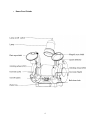
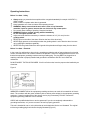
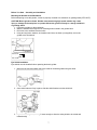
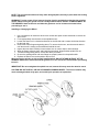
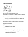
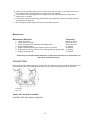
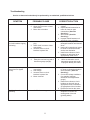
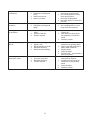
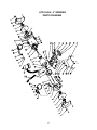
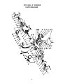
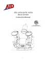
ATD-10556 & ATD-10558 Bench Grinder Instruction Manual 1 Table of Contents SPECIFICATIONS --------------------------------------------------------------------------------------------------- 2 IMPORTANT SAFETY RULES------------------------------------------------------------------------------------3 KNOW YOUR BENCH GRINDER ------------------------------------------------------------------------- 4 OPERATING INSTRUCTIONS-----------------------------------------------------------------------------5--10 MAINTENANCE ----------------------------------------------------------- ------------------------------ 11 TROUBLESHOOTING -------------------------------------------------- ----------------------------1213 EXPLODED VIEW AND PARTS LIST---------------------------------------------------------------------14,15 WARRANTY --------------------------------------------------------------------------------------------------- -------16 Specifications Model # Serial #: Motor Type: Motor Ratings: Horsepower: ATD-10556 Induction 120 V AC, 2.8 A, 60 Hz 1/2 HP Wheel Diameter: Wheel Width: Arbor Hole: No load Speed: Wheel Grits: 6” (15 cm) 3/4" (20 mm) 1/2" (13 mm) 3450 RPM 36 (Coarse) 60 (Medium) Model # Serial #: Motor Type: Motor Ratings: Horsepower: ATD-10558 Induction 120 V AC, 4.8 A, 60 Hz 3/4 HP Wheel Diameter: Wheel Width: Arbor Hole: No load Speed: Wheel Grits: 8” (20 cm) 1” (25.4 mm) 5/8” (16 mm) 3450 RPM 36 (Coarse) 60 (Medium) 2 Important Safety Rules DANGER!! Failure to observe any of the following instructions could result in severe personal injury to tool user and bystanders or cause damage to tool and property! WARNING! – Read, understand and observe all instructions in this manual before using or operating the tool for which it is written and supplied. Ensure that anyone who is to use the tool has read and understood the instructions provided. Always wear eye protection that complies with a recognized standard (CSA or ANSI). Wear a mask or respirator when dust is generated. Keep bystanders out of the work area while operating the tool. WARNING! Always ensure that the work area is clear of any flammable materials, liquids or gasses, because the use of this tool may create sparks. Tighten grinding wheel lock nuts, securing bolts and all clamps and guards. During each start-up, stand to one side of the grinder and switch it „On‟. Let the grinder operate at full speed for approximately one minute so that any undetected flaws or cracks will become apparent. Keep guards in place and working properly. Keep hands clear of grinding wheels. Never reach behind or beneath the grinding wheels. Unplug from power supply before adjusting or servicing. The grinding wheels continue to rotate after the tool is switched off. Always allow wheels to stop before adjusting or servicing. To avoid electric shock, DO NOT use in damp conditions or expose to rain. When fitting a new grinding wheel, always check that the stated maximum RPM meets or exceeds that stated on the grinder. Also check the new wheel for damage, such as flaws or cracks. If the wheel appears satisfactory, fit it to the grinder. When a new grinding wheel has been fitted, stand to one side of the grinder and switch it „On‟. Let the grinder operate at full speed for approximately one minute so that any undetected flaws or cracks will become apparent. Use only accessories that are recommended by the manufacturer for your model. DO NOT attempt to cut anything with the grinding wheel. Grounded tools must be plugged into an outlet that has been properly installed and grounded in accordance with all local codes and ordinances. Never remove the grounding prong from the plug or modify it in any way. Do not use adaptor plugs. If in doubt as to whether the outlet is properly grounded, consult a qualified electrician. Do not use the tool when tired or under the influence of drugs, alcohol or medication. Do not wear loose clothing or jewelery. Keep hair tied back. Ensure the power switch is off prior to plugging in the tool. WARNING! Replace cracked grinding wheels immediately. Do not overtighten spindle nuts. Adjust tool rests whenever necessary to maintain a distance of 1/8” (3.2 mm) from the grinding wheel. Service on these tools should only be performed by an authorized, qualified technician. 3 Know Your Grinder Plain eye shield Guards Tool rest/work rest Bolt-down hole On/off switch Water tray 4 Base – bolt-down area Operating Instructions Before You Start - Safety Always wear eye protection that complies with a recognized standard (for example: ANSI Z87.1) (CSA or ANSI). Wear a mask or respirator when dust is generated. Keep bystanders out of the work area while operating the tool. WARNING! Always ensure that the work area is clear of any flammable materials, liquids or gasses, because the use of this tool may create sparks. Do not wear loose clothing or jewellery. Keep hair tied back. WARNING! Replace cracked grinding wheels immediately. Do not overtighten spindle nuts. Adjust tool rests whenever necessary to maintain a distance of 1/8” (3.2 mm) from the grinding wheel. NEVER grind on the side of the wheel. Grind on the face of the wheel only. NEVER apply pressure to the workpiece when the grinding wheel is cold. Allow the wheel to warm up by applying the workpiece gradually. NEVER use the grinder without the wheel guards. Keep thumbs and fingers away from the wheel. Before You Start – Electrical In the event of a malfunction or short circuit, grounding provides the path of least resistance for electrical current, and reduces the risk of electric shock for the operator. This tool is equipped with an electric cord that has an equipment grounding conductor and a grounding plug. The plug MUST be plugged into a matching outlet that is properly installed and grounded in accordance with ALL local codes and ordinances. DO NOT MODIFY THE PLUG PROVIDED. If it will not fit the outlet, have the proper outlet installed by an electrician. Figure 2 IMPROPER CONNECTION of the equipment grounding conductor can result in increased risk of electric shock. The conductor with the green insulation (with or without yellow stripes) is the equipment grounding conductor. If repair or replacement of the electric cord or plug is necessary, DO NOT connect the equipment grounding conductor to a live terminal. CHECK with a qualified electrician or service personnel if you do not completely understand the grounding instructions, or if you are not sure if the tool is properly grounded. This tool is intended for use on a circuit that has an outlet that looks like the one illustrated. The original tool has a grounding plug that looks like the plug illustrated (Figure 2). 5 Use of Extension Cords USE ONLY THREE-WIRED EXTENSION CORDS that have 3-pronged plugs and 3-holed outlets that accept the tool’s plug. Repair or replace damaged or worn cords immediately. Be sure your extension cord is properly wired and in good condition. Do not use damaged extension cords. Always replace a damaged extension cord. When using an extension cord, be sure to use one heavy enough to carry the current your product will draw. An undersized cord will cause a drop in line voltage, resulting in loss of power and overheating. The table below shows the correct size to use according to the cord length and the amperage draw of the tool (specified on the nameplate). When in doubt, use the next heavier gauge. The smaller the gauge number, the heavier the cord. (AWG = American Wire Gauge). Minimum Gauge for Extension Cords (AWG) (when using 120 volts only) Ampere Rating Total Length of Cord in Feet (meters) More Than Not more Than 25’ (7.6m) 50’ (15m) 100’ (30.4m) 150’ (45.7m) 0 6 18 16 16 14 6 10 18 16 14 12 10 12 16 16 14 12 Not Recommended 12 16 14 12 Use a separate electrical circuit for your tools. This circuit should not be less than a #12 gauge wire, and should be protected with a 15 A time-lag fuse. Before connecting the motor to the power line, ensure the switch is in the OFF position and the electric current is rated the same as the current stamped on the motor’s nameplate. Running at a lower voltage will damage the motor and is not covere d by warranty. Before You Start – Package Contents Left work rest------------------------------------------------------- 1 Right work rest----------------------------------------------------- 1 Plain eye shield-----------------------------------------------------1 Magnifying eye shield---------------------------------------------1 Eye shield adjusting knob ---------------------------------------2 Eye shield mounting rod – one left, one right Eye shield assembly mounting bolt M6x30------------------2 Eye shield assembly mounting washer D6------------------2 Eye shield assembly mounting locking washer D6--------2 Work rest fixing knob----------------------------------------------2 Work rest plain washer D5 ------------------------------------- 2 Work rest lock washer D5 ---------------------------------------2 Coolant tray-----------------------------------------------------------1 Spark deflector------------------------------------------------------2 Spark deflector adjusting screw assembly ------------------2 6 Before You Start – Assembly and Installation Mounting the Grinder to the Workbench Before attempting to use this grinder, it must be properly mounted to a workbench or grinding stand (ATD-10557). CAUTION! Bench grinders vibrate. Grinder movement during high-speed rotation may cause injury or damage to the workpiece or operator. Mount the grinder securely to a sturdy workbench or grinding stand. 1. Position the grinder on the workbench. 2. Mark the workbench through the two mounting holes located in the grinder base. 3. Drill holes in the workbench at the marks. 4. Using two long bolts, washers, lock-washers and nuts, as shown (not supplied), secure the grinder to the workbench. Flat washer Hex nut Eye Shield Installation Eye shields must be installed before operating the bench grinder. 1. Mount the left and right shield rods to the inside of the wheel guards using hex bolts. 2. Once shield rods are firmly in place, slide the shield bracket onto the shield rod. 3. Tighten the carriage bolt, leaving it loose enough to allow the safety shield to be raised and lowered easily 7 NOTE: The eye shield should move freely when being adjusted, but stay in place when the locking knob is tightened. WARNING! Turn the power off and remove the plug from the outlet before changing the grinding wheels. When turning the grinder on with a newly installed wheel, DO NOT STAND IN FRONT OF THE GRINDER. Stand to the side and allow the grinder to run for at least one minute before proceeding to use it. Installing or Changing the Wheel 1. Use a screwdriver to loosen the wheel cover screws and push counter-clockwise to remove the wheel cover. 2. Fit an appropriately sized wrench on the spindle hex nut. 3. Loosen the wheel nut in a clockwise direction for the left side and a counter-clockwise direction for the right side. 4. Remove the outer flange and grinding wheel. To remove the hex nut, turn the wrench and nut until the wrench is resting on the workbench behind the tool. 5. Inspect the new wheel carefully to ensure there are no cracks, chips or other damage. 6. Wipe the flange surfaces clean, and install the new wheel, flange and the spindle hex nut. 7. To install a new grinding wheel, reverse the above procedure. 8. Be sure the grinding wheel and outer flange are properly seated on the spindle shaft. 9. Replace the wheel cover and reposition the tool rest. When turning the grinder on with a newly installed wheel, DO NOT STAND IN FRONT OF THE GRINDER. Stand to the side and allow the grinder to run for at least one minute before proceeding to use it. IMPORTANT! Do not overtighten the spindle hex nut, because this may cause the wheel to crack. CAUTION! DO NOT INSTALL OR USE A DAMAGED GRINDING WHEEL. The force of rotation may cause a damaged wheel to fly apart, and could injure operators or bystanders. 8 Tool Rest Adjustments and Installation Mount the tool rests to the work rest bracket using the knob and washers. Before tightening the knob, adjust the gap between the grinding wheel and the work rest to a maximum of 1/8” (3.2 mm). Tighten securely. Adjustments To prevent the workpiece from being pulled and caught between the tool rest and the wheel, readjust the tool rest position whenever necessary to maintain the 1/8” (3.2 mm) distance. 1. Loosen, but do not remove, the knob holding the tool rest arm. 2. Slide the tool rest in or out to achieve a 1/8” (3.2 mm) distance from the grinding wheel surface. 3. Re-tighten the lock knob. Using Your Bench Grinder This 8” Bench Grinder is ideal for use in sharpening chisels, axes and other wood-cutting tools. It is also useful for repairing tips on screwdrivers and drill bits or for removing excess metal burrs from pieces of cut metal. With the proper accessories, this tool can be used for cleaning metal surfaces using a wire brush or for buffing and polishing using a cloth wheel. ON/OFF The rocker ON/OFF power switch is located on the front of the grinder. 1. Press the side marked ON to turn the grinder on. 2. Press the side marked OFF to turn the grinder off. Grinding Adjust the tool rest to accommodate large or unusually shaped workpieces. Always keep the workpiece moving across the face of the grinding wheel. Grinding continuously on the same spot on the wheel will cause grooves to be worn into the wheel. The wheel may crack or become damaged more easily, and grinding of other objects will be difficult. If the workpiece becomes hot, dip it into the water or oil to cool it. Always grind on the face of the wheel (around the diameter), NEVER on the sides. Side pressure on grinding wheels can cause cracking and damage. 9 If the face of the grinding wheel is worn unevenly, becomes grooved, or is no longer smooth and flat, the wheel should be reshaped with a dressing tool (not supplied). If the diameter of the grinding wheel is no longer round, the wheel should be reshaped with a dressing tool or replaced. If the surface of the wheel becomes loaded and dull with workpiece material, the wheel should be cleaned with a dressing tool. After reshaping, always readjust the tool rests and spark arrestors. Maintenance Maintenance Required 1. 2. 3. 4. 5. 6. 7. Check power cord Check wheels for cracks Check moving parts for alignment and binding issues Dress Grinding Wheels Replace Grinding Wheels (see manual section for specifics) Clean and vacuum dust from the motor housing and other grinder parts Replace work-light bulb Frequency Before each use. Before each use. Before each use. As needed As needed. As needed. As needed Service beyond recommended maintenance on these tools should only be performed by an authorized, qualified technician. COOLANT TRAY When grinding, metal objects become heated quickly. It is important to keep moving the object back and forth across the face of the grinding wheel and to cool the object frequently using the coolant tray. coolant tray Coolant Tray WORK-LIGHT BULB REPLACEMENT Use Max 40 W anti-vibration light bulb 10 Troubleshooting Service on these tools should only be performed by an authorized, qualified technician. SYMPTOM PROBABLE CAUSE Motor will not start. 1. Low Voltage. 2. Open circuit in motor or loose connections. 3. Blown fuse or breaker. Motor will not start –fuses or circuit breakers tripping or blowing. 1. Short circuit in line, cord or plug. 2. Short circuit in motor or loose connections. 3. Incorrect fuses or circuit breakers in power line. Motor overheats. 1. 2. Motor stalls (resulting in blown fuses or tripped circuit). 1. Short circuit in motor or loose connections. 2. Low voltage. 3. Incorrect fuses or circuit breakers in power line. 4. Motor overload. Machine slows when operating. Motor overloaded. Extension cord too long and of insufficient gauge (weight). 1. Feed rate too great. 11 CORRECTIVE ACTION 1. Check power source for proper voltage. 2. Inspect all lead connection on motor for loose or open connections. (Send for Servicing.) 3. Short circuit. (Send for Servicing.) 4. Improper match between tool and circuit, fuse or breaker. 1. Inspect cord or plug for damaged insulation and shorted wires. 2. Inspect all connections on motor for loose or shorted terminals and/or worn insulation. 3. Install correct fuses or circuit breakers or switch tool to an appropriately sized circuit. 1. Reduce load on motor. 2. Utilize an extension cord of appropriate gauge and length or plug tool directly into outlet. 1. Inspect connections on motor for loose or shorted terminals or worn insulation. (Send for Servicing.) 2. Correct low voltage conditions (for example: improper extension cord length and/or gauge). 3. Install correct fuses or circuit breakers or plug tool into an appropriate circuit, matched to an appropriate fuse or breaker. 4. Reduce the load on the motor. 1. Reduce the rate at which the workpiece is fed into the working area of the tool (grinding wheel). Wavy condition on surface of workpiece. 1. Machine vibrating. 2. Workpiece not being held firmly. 3. Wheel face uneven. 4. Wheel is too hard. Lines on surface of workpiece. 1. Impurity on surface of wheel. 2. Workpiece not being held tightly. 1. Ensure machine is securely mounted on a solid surface. 2. Use a holding device to firmly retain the workpiece. 3. Dress the grinding wheel. 4. Use softer wheel, or reduce the feed rate. 1. Dress the grinding wheel. 2. Use a holding device to more firmly retain the workpiece. Burning spots or cracks in the workpiece. 1. 1. 2. 3. Improper type of grinding wheel. Improper feed rate. Coolant required. 2. 3. Wheel dulls quickly, grit falls off. Wheel clogs and workpiece shows burn marks. 1. 2. 3. 4. 5. Feed rate is too aggressive. Wheel is soft. Wheel diameter too small. Bad wheel dressing. Defective wheel bonding. 1. 1. 2. 3. 4. Wheel is too hard. Feed rate is too slow. Bad wheel dressing. Coolant required. 1. 2. 3. 4. 5. 2. 3. 4. 12 Try wheels with softer bond or coarser grit. Slow down the rate at which the workpiece is fed into the wheel. Introduce coolant. Decrease feed rate of workpiece into grinding wheel. Select a grinding wheel with a harder bond of material. Replace wheel. Dress the wheel. DO NOT USE –return wheel to point of purchase. Select a grinding wheel with a softer bond of material. Increase the feed rate of the workpiece into the grinding wheel. Dress the wheel. Introduce coolant. ATD-10556 - 6” GRINDER PARTS DIAGRAM 13 14 PRT10556-25 PRT10556-26 PRT10556-27 PRT10556-28 25 26 27 28 PRT10556-23 PRT10556-24 23 24 PRT10556-21 PRT10556-22 21 22 PRT10556-19 PRT10556-20 19 20 PRT10556-17 PRT10556-18 17 PRT10556-16 16 18 PRT10556-14 PRT10556-15 PRT10556-13 13 14 PRT10556-12 12 15 PRT10556-10 PRT10556-11 10 PRT10556-09 9 11 PRT10556-08 8 ATD-10552 5 PRT10556-06 PRT10556-04 4 PRT10556-07 PRT10556-03 3 6 PRT10556-02 2 7 PRT10556-01 1 ITEM# ORDERING PART# 6202RZ CORD CLIP (6P4) CORD BUSHING OUTER TOOTHED LOCKING WASHER MAGNIFIED EYESHIELD BEARING WAVE WASHER POWER CORD END BELL EYESHIELD LOCKING KNOB LEFT EYESHIELD ASSY HEX BOLT (BLACK) SPRING WASHER (BLACK) FLAT WASHER (BLACK) LEFT EYESHIELD BRACKET LOCKING KNOB LEFT TOOL REST PHILIPS SCREW +FLAT WASHER (WHITE) PHILIPS SCREW (BLACK) SPRING WASHER (BLACK) FLAT WASHER (BLACK) LEFT SPARK DEFLECTOR LEFT GUARD COVER PLATE ASSY PHILIPS SCREW +SPRING WASHER (WHITE) 6" WHEEL COARSE (Φ150×20×Φ12.7) FLANGE (WHITE) HEX NUT (WHITE) LEFT WHEEL COVER PHILIPS SCREW +SPRING WASHER+FLAT WASHER (BLACK) DESCRIPTION D4 D35 M4 M6x30 D6 D6 M5x10 M4x135 M5x8 D5 D5 M5x10 36# M12 Le M5x12 1 1 2 1 2 1 1 2 2 1 2 2 2 1 2 1 4 2 4 2 1 1 6 1 4 1 1 6 QTY 55 54 53 52 51 50 49 48 47 46 45 44 43 42 41 40 39 38 37 36 35 34 33 32 31 30 29 PRT10556-55 PRT10556-54 PRT10556-53 PRT10556-52 ATD-10551 PRT10556-50 PRT10556-49 PRT10556-48 PRT10556-47 PRT10556-46 PRT10556-45 PRT10556-44 PRT10556-43 PRT10556-42 PRT10556-41 PRT10556-40 PRT10556-39 PRT10556-38 PRT10556-37 PRT10556-36 PRT10556-35 PRT10556-34 PRT10556-33 PRT10556-32 PRT10556-31 PRT10556-30 PRT10556-29 ITEM# ORDERING PART# ATD-10556 SPEC DESCRIPTION RIGHT EYESHIELD BRACKET RIGHT TOOL REST RIGHT WHEEL COVER HEX NUT, I TYPE(WHITE) 6" WHEEL MEDIUM (Φ150×20×Φ12.7) RIGHT GUARD COVER PLATE ASSY RIGHT SPARK DEFLECTOR HEX NUT (WHITE) ROTOR STATOR LAMP ASSY PHILIPS SCREW +SPRING WASHER (WHITE) CAPACITOR 8ΜF300V CAPACITOR SUPPORT HEX NUT, I TYPE (WHITE) BIG FLAT WASHER (BLACK) RUBBER FOOT PHILIPS SCREW + BIG FLAT WASHER (WHITE) BASE PLATE COOLANT TRAY PHILIPS SCREW (BLACK) COOLANT TRAY CLIP ROCKER SWITCH SWITCH PLATE BASE PHILIPS SCREW + SPRING WASHER+FLAT WASHER FLAT WASHER (WHITE) SPEC M12 60# M4 M6x18 M8 D5 M4x12 M4x8 M4x8 D12 1 1 1 1 1 1 1 4 1 1 1 2 1 1 1 2 4 4 1 1 4 1 1 1 1 3 1 QTY ATD-10558 - 8” GRINDER PARTS DIAGRAM 15 16 PRT10556-26 PRT10558-28 28 PRT10556-28 25 PRT10556-27 PRT10558-24 24 26 PRT10558-23 23 27 PRT10558-21 PRT10556-22 21 22 PRT10556-19 PRT10556-20 19 PRT10556-18 18 20 PRT10556-16 PRT10556-17 16 PRT10558-15 15 17 PRT10556-14 14 PRT10558-12 12 PRT10558-13 PRT10556-11 13 PRT10556-10 PRT10558-07 7 11 PRT10556-06 6 10 ATD-10554 5 PRT10556-08 PRT10558-04 4 PRT10556-09 PRT10558-03 3 8 PRT10558-02 2 9 PRT10556-01 1 ITEM# ORDERING PART# SPRING WASHER (WHITE) CORD BUSHING OUTER TOOTHED LOCKING WASHER D8 2 1 2 1 CORD CLIP (6P4) 1 1 2 2 1 2 2 2 1 2 1 4 2 4 2 1 1 6 1 4 1 1 6 2 D4 D40 M4 M6X30 D6 D6 M5X10 M5X155 M5X8 D5 D5 M5X10 36# M16 LEFT M5X12 QTY 56 55 54 53 52 51 50 49 48 47 46 45 44 43 42 41 40 39 38 37 36 35 34 33 32 31 30 29 ITEM# ATD-10558 SPEC 6203RZ BEARING WAVE WASHER POWER CORD END BELL EYESHIELD LOCKING KNOB LEFT EYESHIELD ASSY HEX BOLT (BLACK) SPRING WASHER (BLACK) FLAT WASHER (BLACK) LEFT EYESHIELD BRACKET LOCKING KNOB LEFT TOOL REST PHILIPS SCREW +FLAT WASHER(WHITE) PHILIPS SCREW (BLACK) SPRING WASHER (BLACK) FLAT WASHER (BLACK) LEFT SPARK DEFLECTOR LEFT GUARD COVER PLATE ASSY PHILIPS SCREW +SPRING WASHER(WHITE) 8" WHEEL COARSE (Φ200×25×Φ15.88) FLANGE (WHITE) HEX NUT (WHITE) LEFT WHEEL COVER PHILIPS SCREW +SPRING WASHER+FLAT WASHER(BLACK) DESCRIPTION PRT10556-25 PRT10556-55 PRT10558-54 PRT10558-53 PRT10558-52 ATD-10553 PRT10558-50 PRT10556-49 PRT10558-48 PRT10558-47 PRT10558-46 PRT10556-45 PRT10558-44 PRT10558-43 PRT10556-42 PRT10556-41 PRT10556-40 PRT10558-39 PRT10558-38 PRT10558-37 PRT10556-36 PRT10556-35 PRT10556-34 PRT10556-33 PRT10556-32 PRT10558-31 PRT10556-30 PRT10556-29 ORDERING PART# DESCRIPTION MAGNIFIED EYESHIELD ASSY RIGHT EYESHIELD BRACKET RIGHT TOOL REST RIGHT WHEEL COVER HEX NUT, I TYPE(WHITE) 8" WHEEL MEDIUM (Φ200×25×Φ15.88) RIGHT GUARD COVER PLATE ASSY RIGHT SPARK DEFLECTOR HEX NUT(WHITE) ROTOR STATOR LAMP ASSY HEX BOLT CAPACITOR CAPACITOR SUPPORT HEX NUT, I TYPE(WHITE) BIG FLAT WASHER (BLACK) RUBBER FOOT PHILIPS SCREW +BIG FLAT WASHER(WHITE) BASE PLATE COOLANT TRAY PHILIPS SCREW (BLACK) COOLANT TRAY CLIP ROCKER SWITCH SWITCH PLATE BASE PHILIPS SCREW +SPRING WASHER+FLAT WASHER FLAT WASHER M16 60# M5 M8×20 M8 D5 M5x16 M4x8 M4x8 D12 SPEC 1 1 1 1 1 1 1 1 4 1 1 1 2 1 1 1 2 4 4 1 1 4 1 1 1 1 3 1 QTY