1
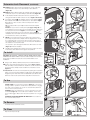
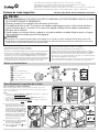
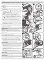
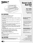
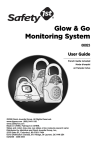
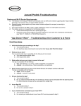
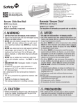
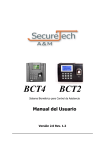
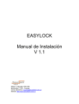
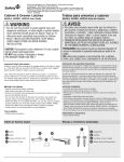
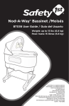
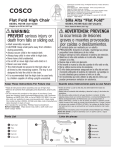
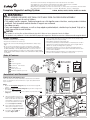
©2010 Dorel Juvenile Group. All Rights Reserved. Todos derechos reservados.
www.djgusa.com (800) 544-1108 www.safety1st.com Made in CHINA. Hecho en CHINA.
Styles and colors may vary. Los estilos y los colores pueden variar.
Distributed by (distribuido por) Dorel Juvenile Group, Inc., 2525 State St., Columbus, IN 47201-7494
Dorel Distribution Canada, 873 Hodge, St. Laurent, QC H4N 2B1 08/13/10 4358-5306A
Complete Magnetic Locking System
HS129, HS130, HS131, HS132, HS133 User Guide
WARNING:
• ADULT ASSEMBLY REQUIRED. KEEP SMALL PARTS AWAY FROM CHILDREN DURING ASSEMBLY.
• Keep magnetic key out of reach of children.
• This product contains magnets. Swallowed magnets can stick together across intestines, causing serious infections
and death. Seek immediate medical attention if magnets are swallowed.
• For indoor use only.
• Toxic and dangerous substances, as well as sharp edged or pointed objects, should always be placed “high up” or
totally inaccessible to small children.
CAUTION:
• This product is not a toy. Do not allow children to play with it. When not in use, keep out of reach of children.
• This product is only a deterrent. It is not a substitute for proper adult supervision. Discontinue use when child becomes old enough to defeat it.
BEFORE YOU BEGIN:
• Tools needed: Hand drill or power drill, 7/64” drill bit, Phillips head
screwdriver & pencil (not provided).
• Door/drawer geometry may prohibit use.
• Avoid close proximity to metal hardware or metal objects stored in
cabinets when planning product placement, as they might make it
difficult to operate the magnetic key properly.
• Avoid letting children see how you operate child safety devices.
Watching you disengage a lock or latch could enable them to learn
sooner how to defeat it.
1B PEEL OFF
1A PEEL OFF
FOLD
• Remove adhesive bumper pads on your cabinet
doors only if they
2
interfere with installation or operation of these locks.
• Read all instructions before installing.
• Keep these instructions for future use.
• Remove all contents from packaging and discard box, and/or poly
bags.
• Do not return this product to the place of purchase. If any parts
are missing, email [email protected], call Consumer Relations
at (800) 544-1108, or fax at (800) 207-8182. You can also visit our
website at www.safety1st.com. Have the model number ready (HS129,
HS130, HS131, HS132, HS133) and date code (manufacture date) located
on product.
1A
PEEL OFF
3
SCREW HOLES
FOR LOCK
Catch
E
Magnetic key
F
Screws (4 per lock)
G
Installation template (1 per lock)
adhere lock as shown
A
Lock
Lock/Unlock button
B
SecureTechTM lock indicator
D
3
SCREW HOLES
FOR LOCK
G
Green = Locked
1B PEEL OFF
Red = Unlocked
F
1A
FOLD
2
3
SCREW HOLES
FOR CATCH
E
PEEL OFF
HS132
Core
A
B
C
D
HS025
ProGrade
FOLD
2
SCREW HOLES
FOR CATCH
For adhesive mount:
mark line
for catch
piece as shown
with red line
mark line
for lock
piece as shown
with red line
Parts & Features
SCREW HOLES
FOR CATCH
SCREW HOLES
FOR LOCK
C
Determine Lock Placement
Cabinet Door and Drawer Types
NOTE:
• Doors with inset panels (Image A) may not have wide enough flat
surface.
• Drawers with outer face panels (Image B) may not have enough room
to install this lock.
• When locks don’t fit at the top of the cabinet, they may fit at the side
(Image C).
1
2
3
Open door/drawer and choose a
possible location to install the lock.
Mark how far down the side of the
door/drawer or how far over on the
top of the door/drawer the lock will
be located (Figures 1a and 1b).
1a
B
A
There are many sizes, shapes and kinds of cabinet doors and drawer
fronts. To determine if our lock will work on your door/drawer follow
steps 1-8 below.
C
Inside
panel
Panel frame
Inset frame
1b
Drawer with outer face panel
2a
Top or side
2b
3
1B PEEL OFF
1A PEEL OFF
FOLD
Close cabinet door/drawer and
mark your lock position on the
cabinet base (Figures 2a and 2b).
2
SCREW HOLES
FOR CATCH
3
SCREW HOLES
FOR LOCK
Peel paper (labeled 1A ) off
template (Figure 3).
1
1B PEEL OFF
SC
FO
Determine Lock Placement
(continued)
4aCabinets— Open door and line up template top or side edge with
4a
pencil mark from step 2. Press down firmly to stick adhesive
(Figure 4a).
1B PEEL OFF
1A PEEL OFF
4bDrawers— Open drawer and line up template side edge with pencil
2
HOLES
SCREW TCH
FOR CA
1B PEEL
6
3
2
2
To Install
7
OK
1B PEEL OFF
Visually inspect marked hole locations of the lock
to make
sure holes
SCREW
HOLES
are both the same distance from edge of door/drawers.
FOR CATCH
FOLD
SCREW HOLES
FOR CATCH
8
SCREW HOLES
FOR LOCK
5
FOLD
Use a pencil to poke through and mark two drill locations for lock
(Figure 6). Remove template.
OFF
FOLD
2
HOLES
SCREW
H
FOR CATC
NOTE: If lock is being mounted on a cabinet door with an inset
panel only the part of the template with the diagonal lines should
be overhanging the recess area of the inset panel.
If any
more of
1B PEEL
OFF
the template hangs over the recess of the inset panel installation in
this location is not recommended.
FOLD
3
SCREW HOLES
FOR LOCK
1B PEEL OFF
HOLES (Figure
Peel paper (labeled 1B ) off template, then closeSCREW
door/drawer
FOR CATCH (Figure
5). Template will transfer from cabinet base to door/drawer
6). If adhesive does not stick, remove bumpers from door or
drawer front.
TIP: You may be able to open adjacent door and ensure template
transfers.
Drawers— If you have an inside panel (see page 1 Image B) on
your drawer front, the bottom of the template must be flat along
the outer panel as shown in Figure 7, or the dotted slots on the
template must be fully on the inner panel as shown in Figure 7.
If template does not fit either of these two recommended options, this
lock should not be used on your drawers.
2
6
OFF
FOLD
SCREW HOLES
FOR CATCH
Fold template inward at dotted line and use a pencil to poke
through and mark two drill locations for catch (Figures
2 4a and 4b).
7
EEL
1B P
mark from step 2. Press down firmly to stick adhesive
(Figure 4b).
FOLD
5
4b
OK
CAUTION: DO NOT DRILL THROUGH CABINET DOOR! DO NOT DRILL
THROUGH THIN INSET PANELS. Follow the drill manufacturer’s instructions
when using your drill. Power tools are not recommended for screw
installation.
9 Using a 7/64” drill bit predrill 3/8” deep holes at marked locations.
10 Position catch with flat side facing out as shown (Figure 7 inset)
and use Phillips head screwdriver to install two screws. Position lock
as shown and use Phillips head screwdriver to install two screws
(Figure 7).
7a
7b
8
9
Test the lock. Set lock to the locked position by pushing the lock/unlock
11
button so the green locking indicator is visible. Close door/drawer. Place
magnetic key over area where lock is installed and open cabinet door/
drawer to ensure it can open and close easily with no interference.
To Use
TO SET LOCK: Press lock/unlock button (Figure 8) so the green
locking indicator position is visible. Close door/drawer to engage
lock. Pull on door/drawer to ensure it is locked. Door/drawer is
now set in the locked position.
TO OPEN: Place the magnetic key over the area where the lock
is installed (Figure 9). You should hear an audible “click” when
the lock disengages. Open door. Close door/drawer to re-engage
lock.
TO DEACTIVATE FOR PERIODS OF NON-USE: Press button to
the red, unlocked position.
To Remove
To remove the lock, remove screws.
To Clean
Green = Locked
Wipe clean. Keep lock dry.
2
Red = Unlocked
©2010 Dorel Juvenile Group. All Rights Reserved. Todos derechos reservados.
www.djgusa.com (800) 544-1108 www.safety1st.com Made in CHINA. Hecho en CHINA.
Styles and colors may vary. Los estilos y los colores pueden variar.
Distributed by (distribuido por) Dorel Juvenile Group, Inc., 2525 State St., Columbus, IN 47201-7494
Dorel Distribution Canada, 873 Hodge, St. Laurent, QC H4N 2B1 08/13/10 4358-5306A
Sistema de traba magnética
HS129, HS130, HS131, HS132, HS133 Guía del Usuario
AVISO:
• REQUIERE ENSAMBLADO POR PARTE DE UN ADULTO. MANTENGA LAS PIEZAS PEQUEÑAS FUERA DEL ALCANCE
DE LOS NIÑOS DURANTE EL ENSAMBLADO.
• Mantenga siempre la llave magnética fuera del alcance de los niños.
• Este producto contiene imanes. Si los imanes son tragados, pueden pegarse entre sí a través de los intestinos y
causar infecciones graves y la muerte. Si los imanes son tragados, obtenga atención médica inmediatamente.
• Solo para uso en interiores.
• Guarde siempre las sustancias tóxicas y peligrosas, así como los objetos con bordes filosos o puntas, en lugares
altos o totalmente inaccesibles para los niños pequeños.
PRECAUCIÓN:
• Este producto no es un juguete. No permita que los niños jueguen con él. Cuando no lo utilice, manténgalo fuera del alcance de los niños.
• Este producto es sólo un elemento disuasivo. El mismo no reemplaza la supervisión adecuada por parte de un adulto. Deje de usar la traba
cuando el niño sea suficientemente grande como para destrabarla.
ANTES DE COMENZAR:
• Herramientas necesarias: Taladro de mano o eléctrico, broca de 7/64
pulg., destornillador Phillips y un lápiz (no incluidos).
• La geometría de la puerta/cajón puede impedir el uso.
•C
uando instale el producto, evite la proximidad a elementos u objetos
metálicos, ya que puede resultar difícil operar la llave magnética correctamente.
• Evite que los niños vean cómo operar los dispositivos de seguridad
para niños. Si lo ven liberar una traba, un pestillo o una cubierta podrían
1B PEEL OFF
1A PEEL OFF
aprender más rápidamente cómo abrirlos.
FOLD
• Retire las almohadillas protectoras adhesivas
de
las
puertas del armario
2
sólo si interfieren con la instalación o la operación de estas trabas.
1A
PEEL OFF
3
SCREW HOLES
FOR LOCK
FOLD
2
SCREW HOLES
FOR CATCH
Enganche
E
Llave magnética
F
Tornillos (4 por traba)
G
Plantilla de instalación (1 por traba)
adhere lock as shown
A
Traba
Botón de traba/destraba
B
Indicador de traba SecureTech™
D
3
SCREW HOLES
FOR LOCK
Verde = Trabada
1B PEEL OFF
Rojo = Destrabada
F
G
1A
FOLD
2
3
SCREW HOLES
FOR CATCH
E
PEEL OFF
SCREW HOLES
FOR LOCK
HS132
Core
A
B
C
D
SCREW HOLES
FOR CATCH
HS025
ProGrade
Piezas y características
For adhesive mount:
mark line
for catch
piece as shown
with red line
mark line
for lock
piece as shown
with red line
• Lea todas las instrucciones antes de instalar.
• Guarde estas instrucciones para su uso futuro.
•R
etire todo el contenido del embalaje y deseche la caja y/o las bolsas de polietileno.
•N
o devuelva este producto al lugar donde lo compró. Si falta alguna pieza,
envíe un correo electrónico a [email protected], llame al Departamento
de Relaciones con el Consumidor al (800) 544-1108, o envíe un fax al
(800) 207-8182. También puede visitar nuestro sitio web en www.safety1st.com.
Tenga a mano el número de modelo (HS129, HS130, HS131, HS132, HS133) y
el código de fecha (fecha de fabricación), indicados en el producto.
C
Para determinar la posición de la traba
Tipos de puertas y cajones de armarios
NOTA:
• Las puertas con paneles enmarcados (Imagen A) posiblemente no tengan una
superficie plana lo suficientemente amplia.
• Los cajones con paneles frontales exteriores (Imagen B) posiblemente no
tengan espacio suficiente para instalar este traba.
• Cuando los trabas no quepan en la parte superior del armario, es posible que
pueda colocarlos en la parte lateral (Imagen C).
1
Abra la puerta/cajón y elija una
ubicación posible para instalar la
traba. Marque la posición vertical en
la parte lateral o la posición horizontal
en la parte superior de la puerta/cajón
donde colocará la traba (Figura 1). Se
recomienda instalar la traba en el marco
del panel y no en el panel enmarcado,
para asegurarse de que los tornillos
no perforen completamente la parte
delantera de la puerta/cajón.
B
A
Existen muchos tamaños, formas y tipos de puertas de armarios y frentes de
cajones. Para determinar si nuestro traba funcionará en su puerta/cajón, siga los
pasos 1 a 8 a continuación.
Panel
interior
Marco del panel
Panel enmarcado
1a
1b
C
2a
Cajón con panel frontal exterior
Parte superior o lateral
2b
3
1B PEEL OFF
2
SCREW HOLES
FOR CATCH
2 Cierre la puerta o el cajón del armario
y marque la posición de la traba en la
base del armario (Figura 2).
3 Retire el papel (etiquetado
plantilla (Figura 3).
1A PEEL OFF
FOLD
1A ) de la
1
1B PEEL OFF
3
SCREW HOLES
FOR LOCK
Para determinar la posición de la traba (continuación)
4aArmarios— Abra la puerta y alinee el borde superior o lateral de la plantilla
4a
con la marca de lápiz del paso 2. Presione firmemente para pegar el adhesivo
(Figura 4a).
1B PEEL OFF
4bCajones— Abra el cajón y alinee el borde lateral de la plantilla con la
marca de lápiz del paso 2. Presione firmemente para pegar
FOLDel adhesivo
4b
1A PEEL OFF
SCREW HOLES
FOR LOCK
FOR CATCH
Retire el papel (etiquetado 1B ) de la plantilla y luego cierre la puerta/
FOLD
3
para perforar y marcar dos puntos de perforación para enganche
SCREW HOLES
(Figura 4a y 4b).
1B PEEL OFF
2
SCREW HOLES
FOR CATCH
(Figura 4b).
6
cajón (Figura 5). La plantilla se transferirá de la base del armario a la
puerta/cajón (Figura 6). Si el adhesivo no se adhiere, retire los topes
de la puerta o el frente del cajón.
CONSEJO: Posiblemente pueda abrir la puerta adyacente y
asegurarse de que la plantilla se haya transferido.
Cajones— Si usted tiene un panel interior (vea image B) en el frente
del cajón, la parte inferior de la plantilla debe estar plana contra el
panel exterior, como se muestra en la Figura 7; o bien, las líneas de
puntos de la plantilla deben quedar completamente en el panel interior,
como se muestra Figura 7. Si la plantilla no se puede colocar en ninguna
de las dos opciones recomendadas, no use esta traba en sus cajones.
1B PEEL
6
NOTA: Si va a instalar la traba en la puerta de un armario con
5
SCREW HOLES
Inspeccione visualmente las ubicaciones marcadas
de los orificios de
FOR CATCH
8
la traba para asegurarse de que ambos estén a la misma distancia
del borde de la puerta/cajón.
7
OK
1B PEEL OFF
Use un lápiz para perforar y marcar dos puntos de perforación para
2
traba (Figura 6). Retire la plantilla.
FOLD
2
SCREW HOLES
FOR CATCH
un panel enmarcado, sólo la parte de la plantilla con las líneas
1B PEEL OFF
diagonales debe sobresalir del área embutida del panel. Si sobresale
una mayor parte de la plantilla sobre el área embutida del panel
FOLD
enmarcado, no se recomienda realizar la instalación en
esta ubicación.
3
7
OFF
FOLD
2
HOLES
SCREW
H
FOR CATC
SCREW HOLES
FOR LOCK
OFF
FOLD
2
HOLES
SCREW TCH
FOR CA
Doble la plantilla hacia dentro por la línea de puntos 2y utilice un lápiz
5
EEL
1B P
OK
Para instalar
PRECAUCIÓN: ¡NO PERFORE COMPLETAMENTE LA PUERTA DEL
ARMARIO! NO PERFORE COMPLETAMENTE LOS PANELES ENMARCADOS
DELGADOS. Al utilizar un taladro, siga las instrucciones de uso del
fabricante. No se recomienda el uso de herramientas eléctricas para la
instalación de tornillos.
Utilizando una broca de 7/64 pulg., perfore orificios guía de 3/8 pulg. de
profundidad en las ubicaciones marcadas.
10Coloque el enganche con el lado plano mirando hacia fuera, como se
9
7a
7b
8
9
muestra (Figura 7, detalle inferior) y utilice un destornillador Phillips
para instalar dos tornillos. Coloque la traba como se muestra y utilice
un destornillador Phillips para instalar dos tornillos (Figura 7).
Pruebe la traba. Coloque la traba en la posición de traba, empujando el
11
botón de traba/destraba para que pueda verse el indicador verde. Cierre
la puerta/cajón. Coloque la llave magnética sobre el área donde está
instalada la traba y abra la puerta/cajón del armario para asegurarse de
que se pueda abrir y cerrar fácilmente sin interferencias.
Cómo utilizar
PARA ACTIVAR LA TRABA:Oprima el botón de traba/destraba
(Figura 8) para que pueda verse el indicador verde de la traba.
Cierre la puerta/cajón para trabar el sistema. Tire de la puerta/
cajón para comprobar que esté trabada. La puerta/cajón ahora
está ahora en la posición de traba.
PARA ABRIR: Coloque la llave magnética sobre el área donde está
instalada la traba (Figura 9). Cierre la puerta/cajón para volver a
trabar el sistema.
PARA DESACTIVAR DURANTE PERÍODOS SIN USO: Oprima el
botón hasta la posición de destraba, indicada por el color rojo..
Para retirar
Para retirar la traba, retire los tornillos.
Para limpiar
Verde = Trabada
Limpie con un paño. Mantenga la traba seca.
2
Rojo = Destrabada