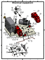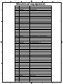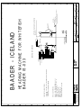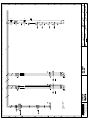
1
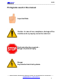
_________________________________________ Operating, Maintenance And Service Manual Spare Parts List IS-033 Round Cut Heading Machine Hafnarbraut 25 Kopavogur Iceland Tel: +354 520 6900 Fax: +354 520 6911 [email protected] www.baader.is IS-033 ___________________________________________________________________________ Preface This manual is dedicated to the personnel responsible for the operation, maintenance and service of a Baader IS-033 Heading Machine. Carefully read the instructions and safety precautions given in this manual. Do not attempt to operate maintain or service this machine until you have thoroughly read and understood the information contained in this manual. It is the responsibility of the owner to ensure training is given to all personnel involved on the operation of these machines. Baader Ísland ehf. Will not assume any liability for damages due to the non-observance of this manual, inadequately trained personnel, improper handling of the machine nor its application in fields other than those specified in this manual. In case of arbitrary modifications by removing or mounting parts or any modification of the machine without our written approval, our conformity declaration (EC directive) will become invalid. Use only Baader genuine spare parts. It is imperative to comply with the legal safety regulations for food processing machinery which are in force in your country. This manual is the intellectual property of Baader Ísland ehf and may not be copied, reproduced nor made available to third parties without our prior written approval. Warning To clearly show details of this machine, covers, guards, barriers or doors may have been removed or shown in an open position. All such safety components must be replaced prior to the machine being used. Failure to observe this instruction may result in serious personal injury or death. _______________________________________________________________________________________ Baader Ísland ehf, Hafnarbraut 25, Kopavogur, Iceland Tel: +354 520 6900 Fax: +354 520 6911 [email protected] / www.baader.is 2 IS-033 ___________________________________________________________________________ Table of Contents 1 2 3 4 5 6 7 8 9 10 11 12 13 14 15 16 17 18 19 20 21 22 23 24 25 26 27 28 29 30 31 32 33 34 Pictograms used in this manual Safety precautions Safety instructions General Technical data Machine set-up Dimensions Power connection Water connection Initial start-up procedure Cleaning Main cleaning Preservation Adjustment of the cycle control proximity switch Adjustment of the locking arm stop Adjustment of the cycle start position Cam alignment position Adjustment of the knife-drive support bracket Adjustment of the transport fork setting distance Replacement of the transport fork cam roller Adjustment of the transport fork Adjustment of the in-feed plate Adjustment of the back plate maximum travel stop screw Adjustment of the angular position of the back plate Adjustment of the back plate minimum travel stop screw Adjustment of back plate travel position Adjustment of the trigger Tension of the knife drive belt Knife replacement Grease lubrication Lubricant change of the gear motors Country related list of cleaning agents and disinfectants Henkel sales partners Lubrication and preservative recommendations 4 5 6 7 8 9 10 11 12 14 15 16 17 19 20 21 23 24 26 27 28 30 31 32 33 34 35 36 37 40 41 42 43 45 _______________________________________________________________________________________ Baader Ísland ehf, Hafnarbraut 25, Kopavogur, Iceland Tel: +354 520 6900 Fax: +354 520 6911 [email protected] / www.baader.is 3 IS-033 ___________________________________________________________________________ Pictograms used in this manual Important Note Caution In case of non compliance, damage of the machine and or property cannot be ruled out. Particular attention required:– Danger of personal injury. Danger Unprotected electrical systems. _______________________________________________________________________________________ Baader Ísland ehf, Hafnarbraut 25, Kopavogur, Iceland Tel: +354 520 6900 Fax: +354 520 6911 [email protected] / www.baader.is 4 IS-033 ___________________________________________________________________________ SAFETY PRECAUTIONS IMPORTANT FOR THE MACHINE OPERATORS! Non-specified use, as well as improper operation of the machine can result in serious bodily injuries and severe material damages. It is essential that operators observe the following safety instructions. Read the operating instructions prior to starting up the machine. Unauthorised personnel must not operate maintain or service the machine. Wear close fitting work clothing, especially around arms. Do not wear any finger rings. Do not reach into running machine. Do not place loose articles on the machine. Do not run the machine unattended. In case of failure of the functional sequence, prior to cleaning, maintenance and lubrication, switch off the machine. Put the machine switch to 0 position and secure it. Only qualified personnel should maintain or service the machine, strictly observing these operating instructions. The safety devices installed by the manufacturer must not be bypassed, modified or removed! Spraying in electrical enclosures and controls gears is prohibited; explosion hazard. Never operate maintain or service this machine if affected by alcohol or other substances that may impair alertness or judgement. Use safety protective equipment. _______________________________________________________________________________________ Baader Ísland ehf, Hafnarbraut 25, Kopavogur, Iceland Tel: +354 520 6900 Fax: +354 520 6911 [email protected] / www.baader.is 5 IS-033 ___________________________________________________________________________ SAFETY INSTRUCTION Prior to starting up the machine: Ensure all machine covers are fitted. Verify the proper functioning of all safety devices. During operation, the machine should stop ... ... when setting the main switch (1) of the heading machine to position 0. ... when pressing the 0-button (2) (red light). ... when actuating the safety lever (3) in front off the in feeding section. 2 3 1 _______________________________________________________________________________________ Baader Ísland ehf, Hafnarbraut 25, Kopavogur, Iceland Tel: +354 520 6900 Fax: +354 520 6911 [email protected] / www.baader.is 6 IS-033 ___________________________________________________________________________ General The machine is designed to remove the head of whitefish with throat cut. It is recommended to wash the fish prior to beheading. Note: Live fish and fish in the state of rigor mortis cannot be processed. _______________________________________________________________________________________ Baader Ísland ehf, Hafnarbraut 25, Kopavogur, Iceland Tel: +354 520 6900 Fax: +354 520 6911 [email protected] / www.baader.is 7 IS-033 ___________________________________________________________________________ Technical Data: Fish Species : Whitefish Process Condition : Throat cut Size range : 1 to 13 kg Throughput rate : Up to 30 fish per minute Power Consumption : 2.2 kW Water supply - Consumption - Pressure - Connection : approx 10 litre per minute : 1 to 5 bar (15 to 75 psi) : 3/8" (hose ID 10mm) Dimensions - Length - Width - Height : 1673mm (65.9") : 930mm (36.6") : 1777mm (70") Weight : 310kg Operator requirements : 1 person Noise measurement (evaluation according to DIN 45635) Workplace level (LpAeq) : 82dB(A) – Wear Ear Protection. The machine is configured for the above mentioned size range and throughput rate. However the proportions and the quality of the fish (season, fishing ground, degree of freshness etc.) have an influence on the figures indicated, these may vary in practice. Live fish and fish in the state of rigor mortis cannot be processed. _______________________________________________________________________________________ Baader Ísland ehf, Hafnarbraut 25, Kopavogur, Iceland Tel: +354 520 6900 Fax: +354 520 6911 [email protected] / www.baader.is 8 IS-033 ___________________________________________________________________________ Machine Set-up The machine shall be readily accessible from all sides for ease of operation and maintenance. Place the machine on the base plates (fig.1 item 1), using the adjusting spindles (fig.1 item 2) level and adjust the working height of the machine. When complete lock the adjusting spindles using the lock nut (fig.1 item 3). 2 3 1 Fig 1 _______________________________________________________________________________________ Baader Ísland ehf, Hafnarbraut 25, Kopavogur, Iceland Tel: +354 520 6900 Fax: +354 520 6911 [email protected] / www.baader.is 9 IS-033 ___________________________________________________________________________ Dimensions 110 700 1098 875 1777 930 1637 350 590 Machine Applications and Features: The fish is placed belly to operator head first into the machine. The fish head is held and the entire fish is transported to the knife section where a high-yield head cut is performed. The main body of the fish, with collarbone attached, discharges to the front of the machine. The head is transported via a chute to the rear. Thanks to its construction, the operator has a clear view of the working area. Adjustments e.g. for adaptations or service operation, including knife replacement are easily performed. _______________________________________________________________________________________ Baader Ísland ehf, Hafnarbraut 25, Kopavogur, Iceland Tel: +354 520 6900 Fax: +354 520 6911 [email protected] / www.baader.is 10 IS-033 ___________________________________________________________________________ Power Connection The machine is supplied with approximately 5m of Ölflex 191 5 G 2.5 cable terminating in a type 416P6 plug which is IP44 splash-proof and conforms to IEC 60 309-2. To comply with the legal safety regulations, the machine has to be connected to the mains electrical supply in accordance with the circuit diagram taking into account the regulations of the local electrical authorities and the rules EN 60204 and VDE 0100. Seal the cable bushes and screw so they are watertight. An electrician must read and understand the electrical drawings supplied with the machine before connecting to the electrical supply. After connecting the machine the electrician should test correct function of the electrical equipment and ensure the machine is correctly grounded. It is important to verify the correct rotation of the electrical motors. Ensure that all exposed electrical equipment is properly covered. Seal the cable bushes and tighten to make watertight. The doors of the cabinet must be closed after the completion of the electrical connection. Always lock the main electrical switch in the OFF position prior to performing any maintenance or service work. Do Not bypass or wire around any safety equipment. Removal of any cover or guard is prohibited. Improper operation or insufficient maintenance can result in serious personal injury and severe material damages. Employees who are responsible for safe working practices have to ensure that :- any maintenance or service work is only completed by qualified personnel. - operating instructions and information required for procedures completed by operators to be available at all times. Operators must strictly observe the contents of this information _______________________________________________________________________________________ Baader Ísland ehf, Hafnarbraut 25, Kopavogur, Iceland Tel: +354 520 6900 Fax: +354 520 6911 [email protected] / www.baader.is 11 IS-033 ___________________________________________________________________________ Water Connection The water connection (fig.2 item1) is configured for 3/8" hose (ID 10mm). The hose should be led from the top down to the machine and secured to the hose tail by means of a hose clip. 1 Water pressure should be a between 1 to 5 bar (15 to 75 psi) Fig 2 _______________________________________________________________________________________ Baader Ísland ehf, Hafnarbraut 25, Kopavogur, Iceland Tel: +354 520 6900 Fax: +354 520 6911 [email protected] / www.baader.is 12 IS-033 ___________________________________________________________________________ Warning Ensure the machine is isolated from the electrical supply before attempting to rotate the machine by hand. Failure to observe this instruction may result in serious personal injury or death. 2 1 3 4 Fig 3 Use a suitable tool to manually rotate the machine (fig.3 item 1) Start-reset button (fig.3 item 2). Note: Pressing the start-reset button for more than 1 second when released the machine will run for 1 complete cycle. Stop button (fig.3 item 3) Safety lever Emergency Stop (fig.3 item 4) _______________________________________________________________________________________ Baader Ísland ehf, Hafnarbraut 25, Kopavogur, Iceland Tel: +354 520 6900 Fax: +354 520 6911 [email protected] / www.baader.is 13 IS-033 ___________________________________________________________________________ Initial Start-up Procedure Prior to starting the machine, remove the preservative from all areas in contact with the product. Wash the machine from bottom to top using a low pressure wash (max 30 bar) with drinking water heated to 60°C. After cleaning, run the machine briefly; grease to remove any cleaning fluid that may have penetrated the bearings. _______________________________________________________________________________________ Baader Ísland ehf, Hafnarbraut 25, Kopavogur, Iceland Tel: +354 520 6900 Fax: +354 520 6911 [email protected] / www.baader.is 14 IS-033 ___________________________________________________________________________ Cleaning Clean the complete machine at regular intervals (8 operating hours). When using low-pressure cleaning devices, do not direct the jet into bearings. Rest periods Set the main switch unto position 0. Remove product remainders and wash the machine from all sides with a powerful water jet. Pre cleaning Start and clean the machine observing the appropriate safety distance from the moving machine parts: with low pressure, max 30 bar. with 60°C drinking water. from bottom to top. Keep the safety distance. Make sure that clothing, hoses, cleaning devices do not get caught by the moving components of the machine; danger of serious bodily injuries and damage to the machine. Do not run the machine unattended. After pre cleaning, stop the machine, set the main switch to position 0 and secure it. _______________________________________________________________________________________ Baader Ísland ehf, Hafnarbraut 25, Kopavogur, Iceland Tel: +354 520 6900 Fax: +354 520 6911 [email protected] / www.baader.is 15 IS-033 ___________________________________________________________________________ Main cleaning The main electrical switch shall be at the 0 position and lock it. Observe the safety instructions at the beginning of this manual. Wear protective clothing during cleaning and sanitation operations. Observe the specific national regulations for the cleaning agents and disinfectants used. Operation Check Device / Method Foam with low2 – 5% P3-topax 17 * pressure foaming device For removing calcareous deposits, use 1 time per week cleaning foam 2 – 5% P3-topax 56 instead of P3-topax 17 Drinking water at Rinse with low 60°C pressure, max 30 bar Visual Sanitation 1% P3-topax 91 Main Cleaning Cleaning Agent Low-pressure spraying, max 30 bar Remarks From bottom to top reaction time 15 minutes From bottom to top reaction time 15 minutes Carefully from top to bottom From top to bottom, reaction time about 10 – 15 minutes since contingent upon germ spectrum; refer to product data sheet Drinking water max Low pressure, Rinse again carefully 20°C max. 30 bar * To avoid white deposits, P3-topax 17 should not be foamed on hot surfaces. Rinsing The cleaning agents P3-topax 17 and P3-topax 56 recommended the avoidance of painted areas of the machine due to aggressive cleaning properties of the products.. After cleaning run the machine briefly and grease to remove any cleaning fluid that may have penetrated the bearings. Correctly dispose of cleaning agents that are ecologically harmful. _______________________________________________________________________________________ Baader Ísland ehf, Hafnarbraut 25, Kopavogur, Iceland Tel: +354 520 6900 Fax: +354 520 6911 [email protected] / www.baader.is 16 IS-033 ___________________________________________________________________________ Preservation Prior to the machine not being used for long periods. Protect the machine using food approved preservatives. Recommended preservatives: Preservation spray MBF 370 – ref. no. 51.10.0201.(400 ml can) Preservation liquid MBF 360 – ref. no. 51.10.0200 (5 l container) These preservatives meet the requirements according to USDA-H1 Before resuming production, remove the preservative from all areas in contact with the product: with low pressure, max 30 bar. with 60°C drinking water. from bottom to top. _______________________________________________________________________________________ Baader Ísland ehf, Hafnarbraut 25, Kopavogur, Iceland Tel: +354 520 6900 Fax: +354 520 6911 [email protected] / www.baader.is 17 IS-033 ___________________________________________________________________________ Back-plate Trigger In-feed plate Fish-chute Transport-fork Head-chute Knife _______________________________________________________________________________________ Baader Ísland ehf, Hafnarbraut 25, Kopavogur, Iceland Tel: +354 520 6900 Fax: +354 520 6911 [email protected] / www.baader.is 18 IS-033 ___________________________________________________________________________ Adjustment of the cycle control proximity switch Prior to working on the machine switch the main electrical switch to the 0 position and lock it. Failure to comply may result in serious personal injury or death. It is important to verify that the proximity switch is correctly located in the holder (fig.4 item 2) prior to adjustment. Loosen the gland nut (fig.4 item 3). Push the cable sheath towards the holder, whilst maintaining pressure re-tighten the gland nut. Loosen the 2 hexagon nuts (fig.4 item 1). 1 2 3 Rotate the machine manually as described on page 13, so that the switch-fane is at its closest position to the proximity switch holder (fig.4 item 2). Adjust the distance between the switchfane and the proximity switch (fig.4 item 2) to 1mm. Fig 4 Re-tighten the 2 hexagon nuts (fig.4 item 1). _______________________________________________________________________________________ Baader Ísland ehf, Hafnarbraut 25, Kopavogur, Iceland Tel: +354 520 6900 Fax: +354 520 6911 [email protected] / www.baader.is 19 IS-033 ___________________________________________________________________________ Adjustment of the locking arm stop Prior to working on the machine switch the main electrical switch to the 0 position and lock it. Failure to comply may result in serious personal injury or death. Loosen the hexagon locknut (fig.5 item 2). 8 mm The machine can be manually rotated as described on page 13, to aid the setting of the locking arm. 3 The rest position of the locking arm should be 8mm below the level of the cam. 1 Adjust the rest position by turning the hexagon head bolt (fig.5 item 1). 2 Re-tighten the hexagon locknut (fig.5 item 2). Fig 5 _______________________________________________________________________________________ Baader Ísland ehf, Hafnarbraut 25, Kopavogur, Iceland Tel: +354 520 6900 Fax: +354 520 6911 [email protected] / www.baader.is 20 IS-033 ___________________________________________________________________________ Adjustment of cycle start position Prior to working on the machine switch the main electrical switch to the 0 position and lock it. Failure to comply may result in serious personal injury or death. Note: The setting of the locking arm stop must be completed prior to adjusting the cycle start position. Loosen (do not remove) the 3 hexagon head bolts (fig.6 item 1). 1 Turn the cam (fig.6 item 2) as far possible anti-clock wise. Re-tighten the 3 hexagon bolts (fig.6 item 1) 2 (continued on next page) Fig 6 _______________________________________________________________________________________ Baader Ísland ehf, Hafnarbraut 25, Kopavogur, Iceland Tel: +354 520 6900 Fax: +354 520 6911 [email protected] / www.baader.is 21 IS-033 ___________________________________________________________________________ Rotate the machine manually as described on page 13 until the ball (fig.7 item 1) touches the cam (fig.7 item 2). 1 2 Fig 7 Direction of Rotation Loosen hexagon bolt (fig.8, item 1). Turn the activating fane (fig.8 item 2). Align the centre line of the fane to the corner of the proximity switch housing. Align Re-tighten hexagon bolt (fig.8 item 1). Cycle start position setting is now complete. 1 Fig 8 2 _______________________________________________________________________________________ Baader Ísland ehf, Hafnarbraut 25, Kopavogur, Iceland Tel: +354 520 6900 Fax: +354 520 6911 [email protected] / www.baader.is 22 IS-033 ___________________________________________________________________________ Cam alignment position Prior to working on the machine switch the main electrical switch to the 0 position and lock it. Failure to comply may result in serious personal injury or death. The upper 2 cams have a setting mark on the uppermost side of the cam. The setting mark for the lowest cam is located on the underside of the of the cam support. _______________________________________________________________________________________ Baader Ísland ehf, Hafnarbraut 25, Kopavogur, Iceland Tel: +354 520 6900 Fax: +354 520 6911 [email protected] / www.baader.is 23 IS-033 ___________________________________________________________________________ Adjustment of the knife-drive support bracket Prior to working on the machine switch the main electrical switch to the 0 position and lock it. Failure to comply may result in serious personal injury or death. Loosen do not remove the 2 hexagon bolts (fig.9A and 9B Items 1 and 2). 1 2 Fig 9 A Fig 9 B (continued on next page) _______________________________________________________________________________________ Baader Ísland ehf, Hafnarbraut 25, Kopavogur, Iceland Tel: +354 520 6900 Fax: +354 520 6911 [email protected] / www.baader.is 24 IS-033 ___________________________________________________________________________ Adjust the inner edge to 184mm (7 ¼") as shown (fig.10). Note: The dimension is taken square to the side of the machine Fig 10 Adjust the outer edge to 34mm (1 5/16") as shown (fig.11). Note: The dimension is taken square to the side of the machine. Re-tighten the 2 hexagon bolts. Fig 11 _______________________________________________________________________________________ Baader Ísland ehf, Hafnarbraut 25, Kopavogur, Iceland Tel: +354 520 6900 Fax: +354 520 6911 [email protected] / www.baader.is 25 IS-033 ___________________________________________________________________________ Adjustment of the transport fork setting distance. Prior to working on the machine switch the main electrical switch to the 0 position and lock it. Failure to comply may result in serious personal injury or death. Manually rotate the machine as described on page 13 to move the transport fork as close as possible to the knife. The transport fork should be 15 to 20mm from the circular knife, see (fig.11). For adjustment see (fig.13). 15 – 20 mm Slacken the hexagon nut (fig.13 item 1) and using the 2 adjusting bolts adjust (fig.13 items 2 and 3) the position of the transport fork. Fig 12 1 3 It is important to ensure that the bolts (fig.13 items 2 and 3) are re-tightened after adjustment. 2 When complete re-tighten the hexagon nut. Fig 13 _______________________________________________________________________________________ Baader Ísland ehf, Hafnarbraut 25, Kopavogur, Iceland Tel: +354 520 6900 Fax: +354 520 6911 [email protected] / www.baader.is 26 IS-033 ___________________________________________________________________________ Replacement of the transport fork cam roller Prior to working on the machine switch the main electrical switch to the 0 position and lock it. Failure to comply may result in serious personal injury or death. Manually rotate the machine as described on page 13 to a ligning the cam roller to th e access hole machined in the cam support plate (fig.14). Slacken the 2 hexagon head bolts (fig.13 items 1 and 2) and remove the hexagon nut (fig.13 item 1). The transport cam roller can now be removed through the access hole. Reverse the procedure to re-assemble. Fig 14 _______________________________________________________________________________________ Baader Ísland ehf, Hafnarbraut 25, Kopavogur, Iceland Tel: +354 520 6900 Fax: +354 520 6911 [email protected] / www.baader.is 27 IS-033 ___________________________________________________________________________ Adjustment of the Transport Fork Prior to working on the machine switch the main electrical switch to the 0 position and lock it. Failure to comply may result in serious personal injury or death. Manually rotate the machine as described on page 13, to move the transport fork as close as possible to the knife. Slacken, do not remove the hexagon bolts (fig.15 item 1 & 2). 1 2 Fig 15 (continued on next page) _______________________________________________________________________________________ Baader Ísland ehf, Hafnarbraut 25, Kopavogur, Iceland Tel: +354 520 6900 Fax: +354 520 6911 [email protected] / www.baader.is 28 IS-033 ___________________________________________________________________________ The distance between the middle of the transport fork to the knife should be between 2 to 3mm in the middle and 10mm at the end. See (fig.16 & 17). Fig 16 2 to 3mm 10mm Re-tighten the hexagon bolts (fig.15 item 1 and 2). Fig 17 _______________________________________________________________________________________ Baader Ísland ehf, Hafnarbraut 25, Kopavogur, Iceland Tel: +354 520 6900 Fax: +354 520 6911 [email protected] / www.baader.is 29 IS-033 ___________________________________________________________________________ Adjustment of the in-feed plate Prior to working on the machine switch the main electrical switch to the 0 position and lock it. Failure to comply may result in serious personal injury or death. Manually rotate the machine as described on page 13, to move the transport fork to the in-feed plate. 2 To adjust the in-feed plate (fig.18 item 2), slacken the 3 hexagon bolts (fig.19 item 1, 2 and 3). 1 The in-feed plate (fig.18 item 2) should be adjusted as close to the transport fork (fig.18 item 1) as possible. Fig 18 It is important that the in-feed plate and the transport fork do not touch during the complete cycle. 3 Re-tighten the 3 hexagon bolts (fig.19 item 1, 2 and 3) 1 2 Fig 19 _______________________________________________________________________________________ Baader Ísland ehf, Hafnarbraut 25, Kopavogur, Iceland Tel: +354 520 6900 Fax: +354 520 6911 [email protected] / www.baader.is 30 IS-033 ___________________________________________________________________________ Adjustment of the back plate maximum travel stop screw. Prior to working on the machine switch the main electrical switch to the 0 position and lock it. Failure to comply may result in serious personal injury or death. Manually rotate the machine as described on page 13, until the back plate reaches its maximum travel. Slacken the lock nut (fig.20 item 1) and adjust the stop screw (fig.20 item 2) to a clearance distance of 16mm (5/8"). 16mm 2 1 Re-tighten the lock nut. Fig 20 _______________________________________________________________________________________ Baader Ísland ehf, Hafnarbraut 25, Kopavogur, Iceland Tel: +354 520 6900 Fax: +354 520 6911 [email protected] / www.baader.is 31 IS-033 ___________________________________________________________________________ Adjustment of the angular position of the back plate. Prior to working on the machine switch the main electrical switch to the 0 position and lock it. Failure to comply may result in serious personal injury or death. Loosen, do not remove, the 2 hexagon head bolts (fig.21 item 1) in the slots. Adjust the back plate angle to accommodate different species of fish. Adjustment in the direction of the RED arrow (fig.21) (closer to neck bone more yield). 1 1 Adjustment in the direction of the YELLOW arrow (fig.21) (away from neck bone less yield). Fig 21 _______________________________________________________________________________________ Baader Ísland ehf, Hafnarbraut 25, Kopavogur, Iceland Tel: +354 520 6900 Fax: +354 520 6911 [email protected] / www.baader.is 32 IS-033 ___________________________________________________________________________ Adjustment of the back plate minimum travel stop screw. Prior to working on the machine switch the main electrical switch to the 0 position and lock it. Failure to comply may result in serious personal injury or death. Manually rotate the machine, as described on page 13, until the back plate reaches its minimum travel. 1 2 Slacken the lock nut (fig.22 item 1) and adjust the stop screw (fig.22 item 2) to maintain a clearance of approximately 10mm (3/8"). Re-tighten the lock nut. Clearance Fig 22 _______________________________________________________________________________________ Baader Ísland ehf, Hafnarbraut 25, Kopavogur, Iceland Tel: +354 520 6900 Fax: +354 520 6911 [email protected] / www.baader.is 33 IS-033 ___________________________________________________________________________ Adjustment of back-plate travel position Prior to working on the machine switch the main electrical switch to the 0 position and lock it. Failure to comply may result in serious personal injury or death. Manually rotate the machine, as described on page 13, until the back plate is approximately in the middle of its travel. 1 Loosen do not remove the hexagon head bolt (fig.23 item 1). 2 3 Adjust the back plate (fig.24, item 2) position by turning the excentric bushing (fig.23 item 2) for the back-plate cam roller (fig. 23 item, 3). The clearance of the back plate to the transport should be approximately 10mm (3/8") (fig.24). Fig 23 Re-tighten the hexagon head bolt (fig.23 item 1) 1 2 Fig 24 _______________________________________________________________________________________ Baader Ísland ehf, Hafnarbraut 25, Kopavogur, Iceland Tel: +354 520 6900 Fax: +354 520 6911 [email protected] / www.baader.is 34 IS-033 ___________________________________________________________________________ Adjustment of the trigger Prior to working on the machine switch the main electrical switch to the 0 position and lock it. Failure to comply may result in serious personal injury or death. It is important to verify that the proximity switch is correctly located in the holder (fig.23 item 2) prior to adjustment. Loosen the gland nut (fig.25 item 5) push the cable sheath towards the holder, whilst maintaining pressure re-tighten the gland nut. 5 4 Loosen, do not remove, the 2 hexagon head bolts (fig. 25 item 1). Adjust the clearance of the proximity switch holder (fig.25 item 2) to 1mm (0.040") (fig.25 item 4). Re-tighten the 2 hexagon head bolts (fig.25 item 1). The trigger weight can be adjusted by loosening the hexagon head nut and bolt (fig.25 item 3) and moving its position along the slot. 1 2 3 Fig 25 When complete re-tighten the hexagon head nut and bolt. Warning It is possible a piece of fish can keep the trigger depressed allowing the machine to continuously cycle. It is important to keep the area around the cycle start trigger clear (see fig.26). Fig 26 _______________________________________________________________________________________ Baader Ísland ehf, Hafnarbraut 25, Kopavogur, Iceland Tel: +354 520 6900 Fax: +354 520 6911 [email protected] / www.baader.is 35 IS-033 ___________________________________________________________________________ Tension of the knife drive belt Prior to working on the machine switch the main electrical switch to the 0 position and lock it. Failure to comply may result in serious personal injury or death. Loosen, do not remove, four hexagon head bolts (fig. 27 item 1). Adjust the tension off the toothed belt (fig. 27 item 2) by lifting the motor plate (fig. 27 item 3) up or down in the slots. 3 1 The correct tension of the toothed belt should allow approximately 20mm (3/4") of movement in the middle of the belt. When complete re-tighten hexagon head bolts. the 2 four Fig 27 _______________________________________________________________________________________ Baader Ísland ehf, Hafnarbraut 25, Kopavogur, Iceland Tel: +354 520 6900 Fax: +354 520 6911 [email protected] / www.baader.is 36 IS-033 ___________________________________________________________________________ Knifes To achieve the best possible results, knife edges should be sharp. The knife is to be verified at regular intervals and be re-sharpened if required. It is necessary to remove the knife from the machine for sharpening. Knife Replacement. Prior to working on the machine switch the main electrical switch to the 0 position and lock it. Failure to comply may result in serious personal injury or death. Danger wear protective gloves when handling knifes. (Part no. 52100196 = 1 off; 2 are included in the tool set) Knife nuts with left–handed threads are marked with notches on the hexagon. Using two 41mm spanners one on the knife shaft and the other on the knife nut slacken the M20 LEFT HAND THREAD knife nut Remove the knife nut. It is now possible to remove the rotary knife. _______________________________________________________________________________________ Baader Ísland ehf, Hafnarbraut 25, Kopavogur, Iceland Tel: +354 520 6900 Fax: +354 520 6911 [email protected] / www.baader.is 37 IS-033 ___________________________________________________________________________ After removal of the rotary knife. Clean the knife mounting face. Replace the rotary knife ensuring the knife drive dogs are located in the rotary knife. _______________________________________________________________________________________ Baader Ísland ehf, Hafnarbraut 25, Kopavogur, Iceland Tel: +354 520 6900 Fax: +354 520 6911 [email protected] / www.baader.is 38 IS-033 ___________________________________________________________________________ Use a suitable food quality anti seize lubricant when re-placing the knife nut. Using two 41mm spanners one on the knife shaft and the other on the knife nut tighten the M20 LEFT HAND THREAD knife nut _______________________________________________________________________________________ Baader Ísland ehf, Hafnarbraut 25, Kopavogur, Iceland Tel: +354 520 6900 Fax: +354 520 6911 [email protected] / www.baader.is 39 IS-033 ___________________________________________________________________________ Grease Lubrication The machine has been lubricated with BAADER ¨Special grease GLS 380/N3¨. This grease is of the GRAS type, semi-synthetic and highly seawater resistant. It complies with the German Food and Consumer Goods Acts (LMBG § 5, art. 1, clause 1) and is authorized according to USDA H1. We recommend using this lubricant at all times. When using other GRAS lubricants, the trouble free functioning of the machine cannot be guaranteed. Ensure only grease free from contaminants is used. Do not blend with mineral lubricants. Note that mineral lubricants do not comply with the provisions of Food and Consumer Goods Acts and may thus not be used. The complete lubrication system (jerk fitting, mouth of grease gun, hand lever press and the coupling) should be free of any impurities! The maximum lubricant pressure at the mouth of the grease gun should not exceed 190 bar. Whenever cleaned, the machine is to be lubricated to expel any cleaning fluids that may have penetrated the machine bearings. _______________________________________________________________________________________ Baader Ísland ehf, Hafnarbraut 25, Kopavogur, Iceland Tel: +354 520 6900 Fax: +354 520 6911 [email protected] / www.baader.is 40 IS-033 ___________________________________________________________________________ Lubricant change of the gear motors Prior to working on the machine switch the main electrical switch to the 0 position and lock it. Failure to comply may result in serious personal injury or death. Unscrew the drain and vent plugs. After draining the oil, flush the gear box thoroughly using suitable flushing oil. Prior to filling the gear motor with new oil, make sure that all flushing oil residue is removed. Replace the drain plug. Checking the oil level: With the gear at rest, the oil must extend to the lower rim of the threaded bore when the oil level screw is removed. Refit the vent plug. The roller bearings should to be cleaned and greased during the same period. Make sure that only one third of the roller bearing space is filled with grease to prevent premature failure. Lubrication change every 2000 hrs or 1 year. _______________________________________________________________________________________ Baader Ísland ehf, Hafnarbraut 25, Kopavogur, Iceland Tel: +354 520 6900 Fax: +354 520 6911 [email protected] / www.baader.is 41 P3-topax 56 Quorum Purple Quorum Pink II P3-topax C 80 P3-clint RI P3-topax 17 P3-topax 17 Quorum Pink II P3-topax 17 TP 17 P3-topax 17 P3-clint RI Quorum Pink II P3-topax 17 P3-rik P3-clint RI Quorum Pink II Quorum Pink II P3-topax 12 P3-topax 12 P3-topax 12 P3-topax 12 P3-topax 12 Quorum Pink II P3-topax 12 TP 12 P3-topax 12 P3-topax 12 Quorum Pink II P3-topax 12 P3-FBC foam P3-topax 12 Quorum Pink II Canada France Germany Greece Italy Japan Namibia Netherlands Norway Poland Russia South Africa Spain United Kingdom Ukraine USA Quorum Amber P3-zinnfest flüssig P3-topax 68 P3-topax 68 Quorum Amber P3-zinnfest flüssig P3-topax 68 TP 68 P3-topax 68 Quorum Amber P3-topax 68 P3-topax 68 P3-topax 68 P3-zinnfest flüssig P3-topax M55 Quorum Amber Quorum Amber P3-topax 68 Quorum Clear P3-topax 99 P3-topax 99 Quorum Clear P3-topax 99 P3-topax 99 TP 99 P3-topax 99 Quorum Clear P3-topax 99 P3-topax SAN P3-topax 99 P3-topax 99 P3-sterylmouss Quorum Clear Quorum Clear P3-topax 99 [email protected] / www.baader.is Baader Ísland ehf, Hafnarbraut 25, Kopavogur, Iceland Tel: +354 520 6900 Fax: +354 520 6911 Quorum Purple P3-topax 56 P3-topax 56 P3-topax 56 Quorum Purple P3-topax 56 P3-topax 56 TP 56 P3-topax 56 P3-topax L54 P3-topax 56 P3-topax 56 P3-topax M acid Quorum Purple Quorum Purple Quorum Pink II Quorum Pink II Brazil P3-topax 56 P3-topax 17 Product P3-topax 12 Country Country related list of cleaning Agents and Disinfectants Ster-Bac P3-topax 91 P3-triquart P3-topax 91 Ster-Bac P3-topax 91 P3-topax 91 Triquart AP P3-triquart Ster-Bac P3-triquart P3-topax 91 P3-topax 91 P3-topax 91 P3-triquart Ster-Bac Ster-Bac P3-topax 91 42 IS-033 Henkel Sales Partners Henkel-Ecolab GmbH & Co.OHG Food & Beverage P3 Division Austria Henkel-Ecolab Gmbh Erdbergstraße 29 A-1031 Wien Österreich Attn: Gerald Hörmann Tel: +43 171 52 55 08 12 Fax: +43 171 52 55 08 54 Belgium Henkel-Ecolab n.v. Doornveld, Industrie Asse 3, Nr.11 B-1731 Zellik-Asse Belgium Attn: Stefan Naten Tel: +32 24 67 51 62 Fax: +32 24 67 51 13 Brazil Ecolab Quimira Ltda Brazil Av. Brigadeiro Luiz Antonio 3767 / 3779 Sao Paolo – SP1401-001 Brazil Attn: Gustavo Miranda Tel: +55 113886-2503 Fax: +55 113885-8479 Bulgarien Henkel-Ecolab Bulgaria Food Prof. Dr. g. Pavlov Str. 35 BG-1111 Sofia Bulgaria Attn: Martin Cheytanov Tel: +359 2 971 22 35 +359 2 971 36 97 Fax: +359 2 971 26 50 Canada Henkel-Ecolab Ltd 5105 Tomken Road Mississauga Ontario L4W 2X5 Canada Attn: Lew Chester/ Bruce Hamilton Tel: +1 905 238 0171 Fax: +1 905 238 0375 Croatia Henkel-Ecolab Zagreb d. o.o. Kucerina 5 HR-10 000 Zagreb Croatia Attn: Dejan Gorsek (Slovenia based) Tel: +385 – 1365 1383 Fax: +385 – 1365 1388 European Operation Reisholzer Werftstr. 34-42 D-40589 Düsseldorf or P.O. Box 13 04 06 D-40554 Düsseldorf Germany Czech Republic Henkel-Ecolab spol. S.r.o. Jakubske namesti 1 CZ-65686 Brno Czech Republic Attn: Peter Slapal Tel: +420 54 22 10 823 Fax: +420 54 22 11 227 Denmark Henkel-Ecolab A/S Carl-Jaocbsens Vej 29-37 DK-2500 Copenhagen-Valby Denmark Attn: Vagn Andersen Tel: +45 36 15 85 85 Fax: +45 36 15 85 99 Tel.: +49 - 211 98 93 203 Fax.: +49 - 211 98 93 223 Germany Henkel-Ecolab Deutschland GmbH Reisholzer Werftstr 38-42 D-40589 Dusseldorf Germany Attn: Walter Hamels Tel: +49 211 98 93 551 Fax: +49 211 98 93 386 Hungary Henkel-Ecolab Kft David Ferenc. Utca t H-1113 Budapest Hungary Attn: Pal Teglasy Tel: +36 1 372 55 76 Fax: +36 1 209 15 44 Ireland Henkel-Ercolab Ltd Beechwood Close, Boghall Road Bray Co Wicklow Ireland Attn: Michael McKenna Tel: +35 31 28 68 225 Fax: +35 31 28 69 298 Italy Henkel-Ecolab S.p.A. Centro Direzionale Colleoni Via Paracelso 6, Palazzo Liocomo 20041 Agrate Branza Milano Italy Attn: Anette Dransfeld Tel: + 39 39 60 50 588 Fax: +39 39 60 50 573 Japan Ecolab K.K. Takadanobaba Center Building 31-18 Takadanaobaba 1-chome Shinjuku-ku, Tokyo 169-8631 Japan Attn: Hideo Oishi Tel: + 81 3 5285 2671 Fax: + 81 3 5285 2680 Netherlands Henkel-Ecolab B>V> Edisonbaan 9-11 NL-3439 MN Nieuwegein Netherlands Attn: Ari de Groot Tel: +31 30 60 82 470 Fax: + 31 30 60 82 479 Greece Henkel-Ecolab A.E. 15, Flemingstr GR 15123 Maroussi-Athens Greece Attn: Diitri Valachis Tel: + 30 16 873 730 Fax: +30 16 841 333 Norway Henkel-Ecolab a.s. Stalverksveien 1,Postboks 6440 Etterstad, N-0605 Oslo Norway Attn: Vagn Andersen (Denmark based) Tel: +47 22 681 800 Fax: +47 22 682 050 Finland Oy Henkel-Ecolab Ab Makelankatu 54 A FIN-00510 Helsinki Finland Attn: Vagn Andersen (Denmark based) Tel: +358 9 39 65 51 Fax: +358 9 39 65 53 05 France Henkel-Ecolab SNC 8, Rue Rouget de Lisle F-92441 Issy-Les-Mouineaux France Attn: Bertrand Laroche Tel: +33 140 93 93 06 Fax: +33 140 93 94 60 _______________________________________________________________________________________ Baader Ísland ehf, Hafnarbraut 25, Kopavogur, Iceland Tel: +354 520 6900 Fax: +354 520 6911 [email protected] / www.baader.is 43 IS-033 ___________________________________________________________________________ Poland Henkel-Ecolab Sp.z.o.o. Ul. Kalwaryjska 69 PL-30504 Krakow Poland Attn: Piotr Kubas Tel: + 48 12 2616 100 Fax: + 48 12 2616 101 Portugal Henkel Ecolab S.A. Estrada Outeiro de Polima Monte Trigo Lote C2 – Aboboda 2775 S Domingos de Rana Portugal Attn: Anette Dransfeld (Italy based) Tel: + 35 12 14 480 750 Fax: + 35 12 14 480 788 Romania Henkel-Ecolab srl (lasi office) 3 Sos,, Nicolina Street Bl 928, parter Lasi R-6600 Romania Attn: Ciprian Petcu Tel: +40 32 221 859 Tel: + 40 32 222 597 Tel: + 40 32 226 459 Fax: + 40 32 226 448 (Bucharest Office) Str. Horia Closca si Crisan Street 61-63 Otopeni, lifov Bucharest R-6600 Romania Tel: + 40 1 203 00 52/53/54/56 Fax: + 40 32 226 448 Russia Henkel-Ecolab Chaussee Entuziastov 14 111,024 Moscow Russia Attn: Alexei V Latyshev Tel: + 7 095 785 27 26 Fax: + 7 095 785 27 25 South Africa/Namibia Klenzade South Africa (Pty) lotd Trading as Ecolab 1 Ampete Street, Chloorkop Edenglen 1633 Tel: + 27 11393 5022 Fax: + 27 11393 1567 Slovakia Henkel-Ecolab Bratislava Spol s.r.o. Zahradnicka 91 82009 Bratislava Slovakia Attn: Robert Krutak Tel: + 421 7 5024 6391/92 Fax: + 421 7 5024 6388 Turkey Henkel-Ecolab Temizleme Sistemleri A>S> Sahrayi Cedid Mah, Halk Sok. No.54 Nokta Is Merkezi Kozyatagi – Istanbul Turkey Attn: Anette Dransfeld (Italy based) Tel: + 90 216 260 99 22 Fax: + 90 216 360 60 81 Ukraine Henkel-Ecolab LLC Bulv. Lichachova, 1/27 Kiev-133 Ukraine Attn: Anatoliy Kindybalyuk Tel: +380 44 29 4 4441 Tel: + 380 44 29 6 6721 Fax: + 380 44 23 0 2873 Slovenia Henkel-Ecolab d.o.o. Vajngerlova 4 SLO-2001 Maribor Slovenia Attn: Dejan Gorsek Tel: + 38 62 42 93 100 Fax: + 38 62 42 96 152 Spain Henkel-Ecolab S.A. Edificio Conata Frucutos Gelabert 2-4, 7 E-08790 San Joan Despi Barcelona Spain Attn: Jose Fernandez Tel: + 34 93 475 8903 Fax: + 34 93 477 0539 Sweden Henkel-Ecolab A/B Box 61 03 Fruangsplan 10 S-12907 Hagersten Sweden Attn: Vagn Andersen (Denmark based) Tel: + 46 8 60 32 200 Fax: + 46 8 60 32 228 United Kingdom Henkel-Ecolab UK Ltd David Murray John Building Swindon, Wiltshire SN1 1ND United Kingdom Attn: Alan Usher Tel: + 44 1 793 54 87 81 Fax: + 44 1 793 54 88 92 USA Ecolab Inc 840 Sibley Memorial Highway St Paul, MN 55118 USA Attn: Shaun Kennedy Tel: + 1 651 306 5857 Fax: + 1 651 552 4821 Switzerland Henkel-Ecolab AG Kriegackerstr 91 CH-4132 Muttenz Schweiz Attn: Marco Moser Tel: + 41 61 46 69 408 Fex: + 41 61 46 69 455 _______________________________________________________________________________________ Baader Ísland ehf, Hafnarbraut 25, Kopavogur, Iceland Tel: +354 520 6900 Fax: +354 520 6911 [email protected] / www.baader.is 44 IS-033 ___________________________________________________________________________ Lubrication and Preservative Recommendation The mineral oil companies listed maintain Technical Services whose engineers will always be available to our customers to give technical advice in lubricating matters. Lubricant Soap Base Din 51502 Code ISO 3498 Viscosity Company Aral BP Castrol Chevron Esso Fina Kluber Mobil Shell Texaco Tribol ICI Molub-Alloy Special lubricants and preservatives Part No. Available sizes 1) 2) Baader Lubrication Grease GLS 380/N3 1) 51.50.0103 51.50.0102 51.50.0109 400 g 25 kg 50 kg Cartridge Hobbock Hobbock Baader Special spray FLC 652) 51.10.0186 Baader Preservation Spray MBF 3702) 51.10.0201 400 ml Can 400 ml Can Baader Preservation Liquid MBF 3602) 51.10.0200 5l Receptacle authorised by USDA-H1. The lubricant is of the GRAS type. comply with the USDA-H1 requirements and is of the GRAS type, semi-synthetic and extremely seawater resistant. _______________________________________________________________________________________ Baader Ísland ehf, Hafnarbraut 25, Kopavogur, Iceland Tel: +354 520 6900 Fax: +354 520 6911 [email protected] / www.baader.is 45 6 5 4 3 2 1 Frame and Covers D D 1 2 1 5 8 C C 6 8 3 B B 1 4 8 10 5 9 A 6 5 4 Item 1 2 3 4 5 6 7 8 9 10 3 Part No. 00106005 03301051 03301052 20600240 30810812 30810825 31800084 31800084 39100288 95030002 Description Cover Machine-Frame Cover Nut M24 Din 934 Hex Head Bolt M8 x 12 Hex Head Bolt M8 x 25 Washer M8 Din 9021 B Washer M8 Din 9021 B Foot plate Adjusting spindle 2 1 A 6 5 4 3 2 1 Cover and Shutes 19 D 24 4 D 19 18 19 1 19 10 23 7 3 13 5 21 15 C C 25 9 22 12 15 17 2 13 21 21 16 14 21 21 20 13 512 16 6 11 B 15 B 12 512 8 12 512 15 Item 1 2 3 4 5 6 A 7 8 9 10 11 12 13 Part No 03101302 03101304 03101306 03301301 03301611 03301612 03303020 03303202 03303303 03303315 03303320 20600080 20600080 6 Description Cover Cover Bar Safety cover Safety cover Fish shute Fish shute Infeed-Table Infeed-plate Head Shute Safety cover Nut M8x1,25 Nut M8 Din 934 5 Item 14 15 16 17 18 19 20 21 22 23 24 25 4 Part No 30810812 30810815 30810820 30810825 30835532 30835533 30835533 31800084 31800084 36020008 37400003 37460421 3 Description Hex Head Bolt M8 x 12 Hex Head Bolt M8 x 16 Hex Head Bolt M8 x 20 Hex Head Bolt M8 x 25 Socket Head Cap Screw M8 x 16 Din 912 Socket Head Cap Screw M8 x 20 Din 912 Socket Head Cap Screw M8 x 20 Washer M8 Din 9021 B Washer M8 Din 9021 B Hexagon Domed Cap Nuts Handle Ball handle 2 1 A 6 5 4 3 2 1 Fish back pressure 26 42 D D 1 35 28 41 40 12 24 28 53 49 10 21 41 25 5 14 53 50 41 49 41 53 21 35 32 16 41 25 C 40 13 27 5 43 41 24 43 25 41 C 26 40 47 20 22 26 23 46 39 34 41 55 53 33 25 25 31 54 30 25 51 25 41 4 6 41 45 15 46 34 11 7 37 38 18 51 23 25 29 40 41 25 52 41 8 41 33 33 52 9 41 2 24 40 B B 25 19 48 36 49 14 41 49 3 5 25 40 28 17 41 25 A A 6 5 4 3 2 1 6 5 4 3 2 1 Fish back pressure D Item Part no Description Item Part no D Description 1 03101005 Collar bolt 29 30810840 Hex Head Bolt M8 x 40 2 03102010 Back plate holder 30 30810850 Hex Head Bolt M8 x 50 3 03102011 Backplate 31 30811020 Hex Head Bolt M10 x 20 4 03102201 Distance shaft 32 30811025 Hex Head Bolt M10 x 25 5 03102253 Stoper bar 33 30811040 Hex Head Bolt M10 x 40 6 03301401 Stoper 34 30811055 Hex Head Bolt M10 x 55 7 03301403 Stoper-Lifter 35 30811060 Hex Head Bolt M10 x 60 8 03301404 Fastener 36 30811080 Hex Head Bolt M10 x 80 9 03301405 Shaft 37 30831008 Locknut M8 Din 985 10 03302005 Arm 38 30835546 Socket Head Cap Screw M10 x 25 Din 912 11 03302008 Fastener 39 30835547 Socket Head Cap Screw M10 x 30 Din 912 12 03302501 Excenter 41 30835549 Socket Head Cap Screw M10 x 40 A2 Din 912 13 03302502 Insert 40 31800084 Washer M8 Din 9021 B 14 03302504 Roller 41 31800105 Washer M10 Din 9021 B 15 03302507 Plate 42 31800170 Washer M16 Din 9021 B 16 03302508 Stoper 43 31801017 Washer 16*50*3 17 03302509 Plate 44 33136205 Ball Bearing stainless 18 03302510 Bearing-Spacer 45 33431615 Du bushing 19 03302511 Spacer 46 33431620 Du bushing 20 03302602 Spring holder 47 33441617 Du collar bushing 21 03302604 Spring-Holder 48 33442008 Du collar bushing 22 03302605 Angle 49 33442512 Du collar bushing 23 03302606 Spring-Holder 50 38010066 Tension spring 24 1891910001 Adjusting bolt 53 38010105 Tension spring 25 20600080 *Varies* 51 39200205 Puffer 25 20600100 Nut M10x1,5 52 73121004 Washer 10,5*40*5 26 20600160 Nut M16x2 53 92202025 Collar bushing 27 30810825 Hex Head Bolt M8 x 25 54 03302603 Pawl plate C C B B A A 28 6 30810835 5 Hex Head Bolt M8 x 35 55 4 30870616 3 Csk Head Screws M6 x 16 2 1 A B C D 5 6 5 Fish transport & cams 6 7 4 6 4 35 47 12 19 28 19 25 33 45 49 39 51 42 43 26 22 26 43 37 10 5 3 24 45 21 3 5 4 45 32 48 3 27 18 23 30 23 30 34 46 11 13 11 16 13 17 42 41 41 40 24 34 46 20 24 2 2 36 29 44 48 48 1 1 50 29 44 14 52 46 15 31 52 14 50 38 8 1 9 2 1 1 A B C D 03101007 03101008 03101012 03101106 03101107 03101208 03301001 03301006 03301009 03301011 03301501 03301207 03301500 03301505 03301510 03301512 03301512a 03301601 2 3 4 5 6 7 8 9 10 11 12 13 14 15 16 17 18 Part No 1 Item Spring cam Spacer Shaft Clamp flange Bearing-Flange Cam washer Fork arm Cam flange Clamp arm Cam disk Bearing Plate Bottom Plate Transport fork Collar - Bushing Flansh Shaft Slott cam Support Description 36 35 34 33 32 31 30 29 28 27 26 25 24 23 22 21 20 19 Item 30835535 30811250 30811060 30811050 30811035 30811025 30810845 30810835 30810820 30810816 30810620 30600161A4 20600100 20600080 1354-7 03303500 03301917 03301603 Part No Hex Socket Head Cap Screw M8 x 30 Din 912 Hex Head Bolt M12 x 50 Hex Head Bolt M10 x 60 Hex Head Bolt M10 x 50 Hex Head Bolt M10 x 35 Hex Head Bolt M10 x 25 Hex Head Bolt M8 x 45 Hex Head Bolt M8 x 35 Hex Head Bolt M8 x 20 Hex Head Bolt M8 x 16 L/Hand Hex Head Bolt M6 x 20 Nut M16 1,5 Nut M10x1,5 Nut M8 Din 934 INA roller Safety plate Lever cam Washer Description 53 52 51 50 49 48 47 46 45 44 43 42 41 40 39 38 37 Item 95502004 03301406 92502013 92143230 38010105 34800309 31800130 31800105 31800105 31800084 31800064 31310840 31310832 31308770 31308736 30835549 30835536 Part No Description Spring pin Bushing F6 40 X 32 Spring pin Bushing F2 32 X 30 Tension spring Conector G1/8*6 Washer M12 Din 9021 B Washer M10 Din 9021 B Washer M10 Din 9021 B Washer M8 Din 9021 B Washer M6 Din 9021 B Key A 10 x 8 x 40 Din 6885 A Key 10 x 8 x 32 Key A 8 x 7 x 70 Din 6885 A Key A 8 x 7 x 36 Din 6885 A Socket Head Cap Screw M10 x 40 A2 Din 912 Hex Socket Head Cap Screw M8 x 35 Din 912 Fish transport & cams Machine Frame 10 11 17 12 9 5 10 8 3 16 4 11 13 15 13 15 10 11 7 14 4 2 14 14 Number 11 10 1 1 1 6 11 10 Part No. DESCRIPTION 1 03101007 Support 2 03301001 Bottom Plate 3 03301002 Side Plate 4 03301003 Back Plate 5 03301004 Top Plate 6 03301006 Bearing Plate 7 03301014 Front Plate 8 03301502 Cable tube 9 13400104 Redjuser G3/8-G1/4 10 30810840 Hex Head Bolt M8 x 40 11 31800084 Washer M8 Din 9021 B 12 34120110A2 Ball valve G3/8 13 34700251 Grease Nipple G1/8 14 34800309 Conector G1/8*6 15 34800324 Conector L G1/8 * 6mm 16 34973359 Conector 1/4 * 8mm 17 83140006 Hose conector A B C D 33 16 31 16 4 6 24 6 5 8 29 7 28 10 1 22 34 12 20 5 Knive Drive 6 5 5 25 16 17 24 28 3 21 30 2 32 23 4 35 22 9 4 18 27 17 19 25 26 31 26 26 Toward knive 15 13 3 Direction off Shaft Sealings 3 14 30 11 2 2 Item Part No. 1 03104001 2 03104002 3 03104003 4 03104004 5 03104005 6 03104301 7 03104401 8 03104402 9 03104901 10 03104902 11 03104903 12 03301305 13 03304006 14 4191600042B 15 20600100 16 30810820 17 30810830 18 30810835 19 30811035 20 30811250 21 30834013 22 30835522 23 31306628 24 31800084 25 31800084 26 31800105 27 32820512 28 33136205 29 34973358 30 35013001 31 35013502 32 37750121 33 73121003 34 73131005 35 94010168 1 Description Knive support Knive shaft Bearing-Flange Bearing-Flange Spacer Belt Cover Bolt Kniveguard Tooth belt pulley Tooth belt pulley Brakemotor 1.1 Kw Cover Support Knive nut Nut M10 Din 934 Hex Head Bolt M8 x 20 Hex Head Bolt M8 x 30 Hex Head Bolt M8 x 35 Hex Head Bolt M10 x 35 Hex Head Bolt M12 x 50 Hexagon Socket Set Screw Socket Head Cap Screw M6 x 16 Key 6X6X28 Washer M8 Din 9021 B Washer M8 Din 9021 B Washer M10 Din 9021 B Pinn Ball Bearing stainless Conector 1/8*8mm Sealing ring 30X42X7 Sealing ring 35X52X07 Tooth belt 8M-20-1040 Washer 8,4*30*4 Washer Circular knive 1 A B C D 6 5 4 3 2 1 Electrical equipment 16 D 34 21 D 11 10 19 42 39 60 HZ 1.2 43 1.1 49 36 8 25 12 46 C 44 28 27 34 2.2 48 C 32 50 17 40 43 2.1 20 34 15 24 17 28 32 B 55 54 52 53 B 35 24 43 14 38 31 7 16 47 13 4 29 23 18 A 50 6 33 35 37 35 45 51 38 9 41 35 3.1 26 A 19 37 33 42 43 6 5 22 39 4 3 2 1 6 5 4 3 2 1 Electrical equipment D C B A 6 Number 1 1.1 1.2 2 2.1 2.2 3.1 4 5 6 7 8 9 10 11 12 13 14 15 16 17 18 19 20 21 22 23 24 25 26 27 28 29 30 31 32 33 34 35 36 37 38 39 40 41 42 43 44 45 46 47 48 49 50 51 52 53 54 55 5 Part No. 03301900 03101902 03101904 03101901 03101902 03101903 03103207 03103203 03103204 03103205 03103309 03104903 03301514 03303206 03303207 03303208 03303216 03303306 03308301 20600060 20600080 20600120 2350604002 30800611 30810615 30810635 30810820 30810840 30811055 30811230 30831006 30835518 30835551 30870816 31010261 31800053 31800064 31800064 31800084 31800105 31800130 33136000 38000374 38010066 39200205 42303109 43400603 69308201 69308202 73121004 94000110 95502004 AB6071685 SA3SE2 120-1B XALD04 ZB5AP3S/ZENL1111 ZB5AP4S/ZENL1121 ZB5AVQ33/ZALVB3 ZB5AVQ43/ZALVB4 4 Description Gear motor i31 60HZ Gear motor Gear i31 60 HZ Gear m tor i39 50HZ Gear motor Gear i39 50 HZ Stoper Bar Bar Bar Activating arm Brakemotor 1.1 Kw Hinge Holder Cover Activator Holder Safety arm Spacer Nut M6x1 Nut M8 Din 934 Nut M12x1,75 Switch holder Hex Head Bolt M6 x 110 A2 DIN 931-1 Hex Set Screw M6 x 16 Din 933 Hex Head Bolt M6 x 35 Hex Head Bolt M8 x 20 Hex Head Bolt M8 x 40 Din 933 Hex Head Bolt M10 x 55 Hex Head Bolt M12 x 30 Locknut M6 Din 985 Socket Head Cap Screw M5 x 45 Socket Head Cap Screw M10 x 50 Din 912 Csk Head Screws M8 x 16 Retaining ring Washer M5 Din 9021 B Washer M6 Din 9021 B Washer M6 Din 125-1B Washer M8 Din 9021 B Washer M10 Din 9021 B Washer M12 Din 9021 B Roller Bearing Compress Spring Tension spring Puffer Sensor Caple fittings Cover Clear cover Washer 10,5*40*5 Washer Spring pin Main switch Switch Buttons case Button I Button 0 Green light lenze Red light lenze 3 2 D C B A 1 Electrical Diagrams Ha f na r br au t 25 - 202 K ó pa v o gur T el : 5 20 6900 F a x : 5 206911 Em ai l : ba a de r @ ba a de r .i s B A A D ER Í SL A ND e h f . BL A CK - 4 0 0 V P O W ER W IRING L 1, L 2, L 3 . BR O W N - 2 3 0 V C ON T R OL V OL T A GE, A n L IGH T BL UE - NEU T R AL , N GR A Y - 2 4 V a c U, A n PURPL E - 2 4 V a c V , B n RED - 2 4 V d c + C n W HI T E - 2 4 V d c 0 V D n OR ANGE - E X T ERN A L V OL T A GE W IRE C OL OR M ARK ING: = FUNC T ION = ( A1) NN 2, ( A1 S Y S T E M GR O OP ), NN 2 FUNC T ION + L O C A T ION - EL E C T RIC AL C O MP ONEN T NUMBER E QUIP MEN T M ARK IN G C ODING: T Y PE E X PL A N A TION C OMP ONEN T NUMBER L O C A TION FUNC TION CR O S S REFER A NCE F OR REL A Y C ON T A C T P A GE.C OLUMN C A BL E W IRE NUMBER TERMIN A L NUMBER TERMIN A L GR OUP GE NE R A L E X PL A N A T IO N W IRE NUMBER L INE CR OS S REF. L INE C ONT INUE ON P A GE 2 C OL UMN 1 L INE N A ME D1 - 2 4 V d c 0 V In c a s e t h e r e = ( f u n c t i o n) a n d o r + ( l o c a t i o n) c o d e a r e n o t s h o w n, c o mp o n e n t t ak e c o d e n u m b e r f r o m d r a w in g f r a m e. HE A D IN G M A C HINE F O R W HI T E F IS H B A A DER IS - 0 3 3 B A A D E R - IC E L A ND Ha f na r br au t 25 - 202 Kó pa v o gur T el: 5 20 6900 F a x : 5 206911 Email: ba a de r @ba a de r .i s B A A D ER Í SL A ND e h f . P O W ER SUPPL Y 3 X 4 0 0 V 5 0Hz 16 A -M1 -M2 -F4 14 9 8 -F2 36 15 32 38 34 37 39 13 -F5 -F3 Ha f na r br au t 25 - 202 Kó pa v o gur T el: 5 20 6900 F a x : 5 206911 Email: ba a de r @ba a de r .i s B A A D ER Í SL A ND e h f . S5 EMERGENCY STOP 21 22 23 V1 24 S1 V2 V4 - K3 13 V3 14 S4 29 V5 -H2 GREEN K10 14 11 EMERGENCY STOP B1-STOP 12 14 20 B2-START 1: F1 2: WM1/2 3: K3 K4 4: K5..K10 5: U1 6: Q1 7: K1 K2 8: WM3/4 IS-033 Elecktrical parts 1 2 3 4 5 6 7 8 9 : : : : : : : : : F1 WM1/2 K3/4 K5..K10 U1 Q1 K1..K2 WM3/4 T1 = = = = = = = = = AB6064675 AMP1,25 AB6063040 SALZX:RT4A4L24 BLOK-PSR230/24-2,5 AB6071685 AB6061773 AMP1,25 BLOK-STU250/2x115 Fuse Fuse Time relay Relay Transformer Main switch Relay Fuse Transformer 9: T1