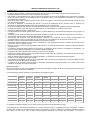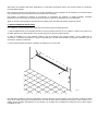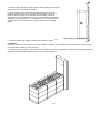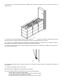
1
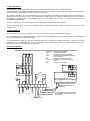
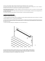
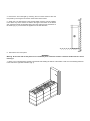
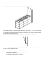
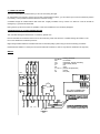
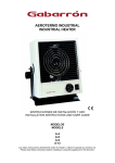
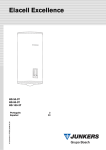
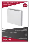
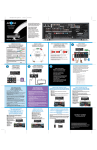
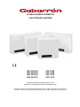
ACUMULADORES DINÁMICOS FAN STORAGE HEATERS ADL 5030/14 ADL 4024/14 ADL 3018/14 ADL 2012/14 ADL 5030 ADL 4024 ADL 3018 ADL 2012 INSTRUCCIONES DE INSTALACIÓN Y USO INSTALLATION INSTRUCTIONS AND USER GUIDE Lea estas instrucciones atentamente antes de instalar o utilizar el aparato por primera vez. Please read these instructions before installing or using this appliance for the first time. INSTRUCCIONES DE INSTALACION Y USO 1.- IMPORTANTE Lean estas instrucciones antes de conectar este aparato por primera vez La garantía del acumulador no cubrirá cualquier daño causado por la no observancia de alguna de estas instrucciones. Este manual debe ser conservado y dado a cualquier nuevo usuario. Este aparato no está destinado a ser usado por personas (incluidos niños) cuyas capacidades físicas, sensoriales o mentales estén reducidas o carezcan de conocimiento del uso del aparato, salvo si son supervisados o instruidos por una persona responsable de su seguridad. Después de haber vuelto a instalar el aparato en otro lugar, se pondrá en funcionamiento durante el primer período de carga bajo el control del instalador. Si durante la instalación y ensamblaje del aparato, una parte del aislamiento térmico muestra daños o deterioro que perjudiquen la seguridad del aparato, deberá ser reemplazada por una pieza idéntica. El uso de acumuladores está prohibido en locales donde haya gases, explosivos o se manipulen sustancias inflamables. No utilizar este aparato para secar ropa. No cubrir el aparato, ni colocar objetos en contacto con el mismo. No tapar las rejillas de entrada o salida de aire. Las superficies del acumulador pueden estar calientes. Los niños deberían ser supervisados para asegurar que no juegan con el aparato. Compruebe que el voltaje de la placa de características del aparato coincide con el voltaje de la red donde se va a conectar. Si quiere dejar fuera de servicio el aparato desconéctelo de la instalación. Este aparato está destinado a ser permanentemente conectado a una instalación fija. El circuito de alimentación del acumulador debe incorporar un interruptor de corte omnipolar con una separación de contactos de al menos 3 mm. El aparato no debe estar situado justamente debajo de una toma de corriente. Este aparato deberá instalarse de forma que los interruptores y otros dispositivos de mando no puedan ser tocados por una persona que esté en la bañera o ducha. El tiempo de carga nominal de este acumulador está indicado en su placa de características y debe ser controlado utilizando un programador. La instalación del aparato debe realizarse de acuerdo con la legislación eléctrica vigente. La instalación o reinstalación, y la puesta en servicio debe ser realizada por un instalador eléctrico cualificado. Es imprescindible que el aparato esté conectado a una buena toma de tierra. Después del montaje, vigilar la primera carga hasta verificar la interrupción de la misma por el termostato de control de carga. Durante este ciclo airear la habitación. Antes de realizar cualquier operación en el interior del aparato, no olvidar desconectar la alimentación eléctrica. No abrir nunca el aparato estando éste cargado. Para mantener la estabilidad, es esencial que el acumulador esté colocado en una superficie lisa y se tendrá cuidado en evitar superficies irregulares de alfombras o baldosas. La presencia en el ambiente de humo de tabaco o partículas en suspensión, polución atmosférica, etc., puede, oscurecer las superficies de paredes cercanas al acumulador. GENERALIDADES Estos acumuladores de calor, están diseñados para el aprovechamiento de tarifas eléctricas con discriminación horaria, en las viviendas y locales que la tengan contratada. Las características de estos modelos son las reflejadas en el siguiente cuadro: Modelo ADL 2012/14 ADL 3018/14 ADL 4024/14 ADL 5030/14 ADL 2012 ADL 3018 ADL 4024 ADL 5030 Potencia 1200W 1800W 2400W 3000W 2000W 3000W 4000W 5000W Tensión 220–240V~ 220–240V~ 220–240V~ 220–240V~ 220–240V~ 220–240V~ 220–240V~ 220–240V~ 14 h 14 h 14 h 14h 8h 8h 8h 8h Acumulación 16 kWh 24 kWh 32 kWh 40 kWh 16 kWh 24 kWh 32 kWh 40 kWh Peso total 123 kg 173 kg 225 kg 277 kg 123 kg 173 kg 225 kg 277 kg Largo 63 cm 81 cm 99 cm 117 cm 63 cm 81 cm 99 cm 117 cm Ancho 24 cm 24 cm 24 cm 24 cm 24 cm 24 cm 24 cm 24 cm Alto 66 cm 66 cm 66 cm 66 cm 66 cm 66 cm 66 cm 66 cm 12 18 24 30 12 18 24 30 Horas de carga Ladrillos La carga del acumulador se regula con un mando exterior que actúa sobre el termostato de carga. La descarga de los acumuladores dinámicos se produce cuando funciona el ventilador que llevan incorporado. La turbina introduce una corriente de aire fresco hacia el interior del acumulador, donde se calienta. Un dispositivo bimetálico mezcla el aire caliente con aire fresco para conseguir una temperatura homogénea en la salida del acumulador. La conexión y desconexión del ventilador debe estar gobernada por un termostato de ambiente externo que no está incluido en el suministro del acumulador dinámico. Para conseguir el máximo ahorro energético con el mejor rendimiento en una instalación de acumuladores, es necesario realizar una correcta elección tanto del número como de la potencia de los mismos. Para facilitar el transporte los bloques de acumulación se suministran por separado, en distinto embalaje. Pequeñas imperfecciones en las esquinas de los bloques de acumulación no afectan al rendimiento de los acumuladores. Según el nivel de carga adquirido la superficie del acumulador puede estar bastante caliente, téngalo en cuenta. 2.- INSTRUCCIONES DE INSTALACIÓN Para realizar la correcta instalación del acumulador es necesario seguir los siguientes pasos: 1.- Elija el emplazamiento del acumulador teniendo en cuenta las distancias entre él y los muebles o cortinas de su entorno. Es necesario mantener una distancia libre de 50 cm para asegurar una buena circulación del aire. 2.- Abra el embalaje por el lugar indicado. Retire la caja de accesorios que contiene tornillos y tacos, resistencias de acumulación, y elementos de sujeción a la pared. Compruebe que el modelo de acumulador corresponde al solicitado y que se encuentra en perfectas condiciones. 3.- Fije a la pared la pieza de sujeción, realizando los taladros a 61 cm del suelo. fig. 1 Este dispositivo impide que vuelque el acumulador cuando se aplica en la parte superior una fuerza hacia el exterior de hasta 20 kg. No es valido para colgar el acumulador de él. En caso de duda sobre la resistencia de la pared o suelo consulte con un experto. El peso de estos acumuladores es muy elevado y es necesario que el instalador se asegure de que no existe ninguna posibilidad de vuelco. 4.- Retire la rejilla quitando los cuatro tornillos. Retire también el panel frontal quitando los dos tornillos de la parte inferior. 5.- Fije al aparato los dos separadores laterales incluidos en la caja de accesorios utilizando para ello los tornillos suministrados así como los ya fijados en la parte superior de los laterales del acumulador. Coloque el acumulador en su emplazamiento definitivo. Encaje y atornille el acumulador al dispositivo antivuelco del paso 3.-. Compruebe que el acumulador queda separado 25 mm de la pared tanto en la parte superior como en la parte inferior. 6.- Quite los tornillos que sujetan el panel de cierre interior y retírelo. fig. 2 ¡ ATENCIÓN ! En la parte posterior de esta chapa se encuentra adherido un delicado panel de aislamiento MICROTHERM, se debe manejar con extraordinario cuidado, procure no tocarlo. 7.- Coloque una fila de ladrillos y sobre ella inserte una de las resistencias de acumulación. Introduzca la resistencia a través de los taladros del aislamiento lateral derecho tal y como muestra la figura 3 fig. 3 8.- Compruebe que la resistencia descansa por completo sobre los ladrillos sin impedir que se coloque una nueva fila de ladrillos, figura 4. fig. 4 9.- Coloque dos nuevas filas de ladrillos, siempre con la cara lisa hacia abajo e inserte otra resistencia. Repita la operación para la tercera resistencia. Disponga la última fila de ladrillos procurando no dejar espacios entre los mismos. 10.- Conexione el acumulador siguiendo las indicaciones del esquema eléctrico, comprobando que no existan conexiones defectuosas o terminales flojos. No deje cable sobrante en el interior del acumulador. 11.- Vuelva a montar el panel de cierre interno solapando la parte inferior. Si el montaje de los ladrillos ha sido correcto no encontrará ninguna dificultad. fig. 5 12.- Coloque el panel frontal, primero colgando el mismo de la “V” existente en la parte superior y colocando los dos tornillos de la parte inferior. 13.- Finalmente, fije la rejilla con los cuatro tornillos. INSTALACIÓN DEL TERMOSTATO ELECTRÓNICO A DISTANCIA Para los acumuladores dinámicos suministrados con la opción CON TELEMANDO. - Fijar el módulo a la pared en posición vertical. - Conectar según el esquema correspondiente respetando el código de colores. - No dejar cable sobrante en el interior del acumulador. - El termostato electrónico a distancia cuenta con instrucciones de uso propias. 3.- MODO DE EMPLEO El mando giratorio regulado del 1 al 5 y situado en el lateral derecho del aparato, regula la carga del mismo. En media estación es suficiente con situar el mando en posiciones intermedias. En estación fría puede seleccionarse la posición 5. En esta posición el acumulador obtiene el máximo nivel de carga. El acumulador requiere para su funcionamiento de un buen termostato de ambiente que controle la puesta en marcha de la turbina interna y así la cesión de calor. Un cronotermostato también puede ser utilizado, controlando en este caso tanto la temperatura de ambiente como la programación de la misma a distintas horas del día. La opción de suministro CON TELEMANDO está disponible. Por favor, consulte las instrucciones específicas de los dispositivos que finalmente sean utilizados. Durante los primeros ciclos de carga es posible que surjan olores. Se recomienda ventilar las habitaciones hasta que estos desaparezcan. 4.- MANTENIMIENTO Este acumulador de calor, una vez puesto en servicio, no necesita ningún tipo de mantenimiento especial. El polvo depositado en la superficie del aparato, puede ser eliminado utilizando un trapo húmedo, cuando el acumulador esté frío. No use disolventes ni productos abrasivos. Los acumuladores de calor ADL han sido fabricados dentro de un sistema de calidad asegurada y conforme a procesos respetuosos con el medio ambiente. Una vez finalizada la vida útil del aparato, llévelo a un punto limpio para que sus materiales puedan ser reciclados de forma adecuada. ESQUEMA ELÉCTRICO INSTALLATION INSTRUCTIONS AND USER GUIDE 1.- WARNING Please read these instructions before installing or using this appliance for the first time. The warranty of the storage heater will not cover any damage caused by non observance of any of these instructions. This Guide must be kept and given to any new owner. This appliance should not be used by disabled persons of any kind (children included) or without notice or knowledge of its use, except in case they are instructed and supervised by a responsible person. Should the heater be moved and reinstalled it is essential that the work is carried out by a fully qualified engineer. If during any installation the thermal insulation shows any sign of damage, it is necessary for the faulty part to be removed and replaced by an identical part. The use of storage heaters is forbidden in any area where there is a presence of gases, explosives or inflammable objects. Do not use this heater to dry clothes. Do not cover this heater or put objects in contact. The air outlet grill at the top of the heater cabinet and the air inlet at the bottom of the heater are provided to ensure the most efficient operation of the appliance. They also protect the heater from overheating; therefore, it is essential that at no time are they covered. Surfaces of this appliance could be hot. Children should be supervised to ensure they do not play with the heater. Check the voltage in the rating label is the same than supply. This heater should be switched off at the isolating switch before any repair work is carried out. This action should also be taken during the times of the year when heat is not required. The installation of the heaters must be carried out in such a way that each pole can be disconnected from the supply having a contact separation of at least 3 mm. The storage heater should not be installed just below an electrical socket. The appliance must be installed in such a way that it is impossible for anyone using a bath or shower, to touch the controls. The nominal charging time of this storage heater is indicated on its rating plate and must be controlled by means of a programmer. The installation must be carried out in accordance with the current electrical regulations. This appliance must be earthed. After installation a survey of the first charging cycle should be carried out to ensure that the main input thermostat switches off. Ventilate the room during this first cycle. Before carrying out any work inside the appliance, the heater must be disconnected from the electricity supply. Never open a charged heater. To maintain stability, it is essential that the heater is placed on a level surface and care should be taken to avoid irregular surfaces, such as may result from carpets or tiled surrounds partially protruding under the heater. The presence in the air of particles of smoke, dust and other pollutants could, in time, discolour the walls and surfaces around the heater. INTRODUCTION Storage heaters are designed to take advantage of the considerable economical benefits of any restricted hour electricity tariff. The heaters consume electricity only during the off-peak tariff, but due to the highly efficient storage medium, give you a truly economical 24 hours of comfort temperatures. Supply with 220-240V~. Model ADL 2012/14 ADL 3018/14 ADL 4024/14 ADL 5030/14 ADL 2012 ADL 3018 ADL 4024 ADL 5030 Input 1200W 1800W 2400W 3000W 2000W 3000W 4000W 5000W Voltage 220 – 240V~ 220 – 240V~ 220 – 240V~ 220 – 240V~ 220 – 240V~ 220 – 240V~ 220 – 240V~ 220 – 240V~ 14 h 14 h 14 h 14 h 8h 8h 8h 8h Charge 16 kWh 24 kWh 32 kWh 40 kWh 16 kWh 24 kWh 32 kWh 40 kWh Weight 123 kg 173 kg 225 kg 277 kg 123 kg 173 kg 225 kg 277 kg Length 63 cm 81 cm 99 cm 117 cm 63 cm 81 cm 99 cm 117 cm Wide 24 cm 24 cm 24 cm 24 cm 24 cm 24 cm 24 cm 24 cm Height 66 cm 66 cm 66 cm 66 cm 66 cm 66 cm 66 cm 66 cm Bricks 12 18 24 30 12 18 24 30 Máx. Charging time The input control operates a highly sensitive thermostat which regulates the amount of heat stored. The discharge takes place when the built-in blower operates. The blower drives fresh air through the core and is heated. A bimetallic device mixes the hot air with fresh air to provide homogeneous temperature. It is important that the correct rating of heater is installed to provide the selected level of heat. This will ensure the best possible running costs against other fuels. To avoid transport problems, the heater casings and storage bricks are packed separately. The bricks with some slight defects in the corners can be used. You should be aware that storage heaters, when fully charged, can have high surface temperatures. 2.- INSTALLATION INSTRUCTIONS Installing the controlled storage fan heater. 1.- Chose the right place to install the heater, considering the minimum distances between heater and other objects. It is needed a minimum distance of 50 cm., to assure a good heat delivery. 2.- Open the carton box by the indicated side, and remove the box containing the accessories, electrical elements and parts to fix to the wall. Turn upside down the box so the heater stands up on its feet and remove the shipping carton. Check the type is the asked and it is O.K. 3.- Screw on the wall the fixing part, making drills at 61 cm over de floor (Fig. 1). fig. 1 This device prevents the heater overturning when a force of up to 20kg is applied to the upper parts to the exterior. The function of the device is not to hang the heater. If there is any doubt as to the strength of the wall, please consult an expert. Storage heaters are very heavy and the installer must ensure that they are securely fixed and there is no possibility of them overturning. 4.- Remove the front outlet grill by removing the four screws. Remove also the front panel by removing the two screws at the bottom of the heater. 5.- Attach the LH & RH spacers to the storage heater using the screws supplied, in the same way as the screws are fixed in the upper rear section of the heater side. Check the heater is separated 25mm from the wall at the top and bottom of the heater (Fig. 2). Fit and screw the appliance to the anti-tilt device. fig. 2 6.- Remove the inner front panel. WARNING ! Warning. At the other side of this part there is a breakable panel of thermal isolation. It must be handle with care. Avoid touching it. 7.- Place a row of storage bricks carefully, with the flat side heading the bottom of the heater. Insert one of the heating elements in the holes in the right side insulation (Fig. 3). fig. 3 8.- Check that the heating element rests completely on the bricks without restricting a new row (Fig. 4). fig. 4 9.- Arrange two new rows of bricks, ensuring the flat side of each bricks is facing towards the bottom of the heater, and insert a new heating element. Repeat the operation for the third heating element. Place the last row of bricks also with the flat side toward the bottom of the heater. Check there is no gap between bricks. 10.- Connect the heater following the enclosed diagram. Ensure all connections are correct and that no connection is damaged. Do not leave any remaining wire inside the heater. 11.- Refit the inner front panel. If the bricks have been fitted correctly you will find no difficulty during this action. fig. 5 12.- Attach the front panel by hanging i ton the “V” in the upper part and securing it at the bottom with the two screws. 13.- Finally, fit the outlet grill with the four screws. INSTALATION OF THE WIRELESS AMBIENT THERMOSTAT (OPTIONAL). - Fix the module to the wall vertically. - Connect the module following the attached diagram and the color code. - Do not leave any remaining wire inside the heater. - The wireless ambient thermostat has its own instructions. 3.- USING THE HEATER The input control allows to lead the heat you want to store during the night. On mild weather it is enough to set the input control at intermediate positions, you can set the input control at maximum position if necessary. In this position the heater stores the maximum energy. Controlled storage fan heaters deliver their heat from a highly insulated core by means of a silent fan. This fan should be managed by a good remote thermostat. During the first cycles some odors are possible; in this case ventilate the room until they disappear. 4.-MAINTENANCE OF YOUR STORAGE HEATER This controlled storage fan heater does not need any special care. Dust accumulated on the heater surface can be removed using a wet cloth when the controlled storage fan heater is cold. Do not use dissolvents or abrasive products. Night storage heaters ADS are manufactured under an assured quality system using environment friendly procedures. Please take the heaters to a clean point once their useful life is finished, in order to recycle their materials in the right way. WIRING E: ADVERTENCIA: Para evitar sobrecalentamientos, no cubrir el aparato de calefacción. UK: WARNING: In order to avoid overheating do not cover the heater. E El símbolo en el producto o en su embalaje indica que este producto no se puede tratar como desperdicio normales del hogar. Este producto se debe entregar al punto de recolección de equipos eléctricos y electrónicos para reciclaje. Al asegurarse de que este producto se deseche correctamente usted ayudará a evitar posibles consecuencias negativas para el ambiente y la salud pública, lo cual podría ocurrir si este producto no se manipula de forma adecuada. Para obtener información más detallada sobre el reciclaje de este producto, póngase en contacto con la administración de su ciudad, con su servicio de desechos del hogar o con la tienda donde compró el producto. Estas disposiciones solamente son válidas en los países miembros de la UE. UK The symbol on the product or in its packaging indicates that this product may not be treated as household waste. Instead it shall be handed over to the applicable collection point for the recycling of electrical and electronic equipment. By ensuring this product is disposed of correctly, you will help prevent potential negative consequences for the environment and human health, which could otherwise be caused by inappropriate waste handling of this product. For more detailed information about recycling of this product, please contact your local city office, your household waste disposal service or the shop where you purchased the product. These instructions are only valid in the EU member states. Fabricado por ELNUR s.a. Pol. Ind. “El Nogal” Travesía de Villa Esther, 11 28110 Algete (MADRID) Tf. de atención al cliente: 902 19 57 14 www.elnur.es Como parte de la política de mejora continua Elnur s.a. se reserva el derecho a realizar modificaciones técnicas sin previo aviso. As a part of the policy of continuous product improvement Elnur s.a reserves the right to alter specifications without notice. @2012 rev.05 Cód. 20290161