1
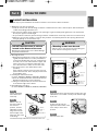
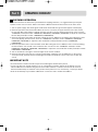
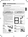
ENGLISH
ESPAÑOL
INSTALLATION MANUAL
ELECTRIC CONVECTION
BUILT-IN OVEN
Please read these instructions thoroughly before
installing and operating the oven.
LWS3081ST
LWD3081ST
LWS3010ST
LWD3010ST
LSWS3034ST
LSWD3034ST
www.lg.com
MFL51224802_06
Part 1
SAFETY
1 BEFORE YOU BEGIN
Remove all tape and packing materials before using the oven. Dispose of all plastic bags after unpacking the oven.
Never allow children to play with packing materials.
You can download an Installation manual at http://www.lg.com.
IMPORTANT SAFETY INSTRUCTIONS
Read and follow all instructions before using your oven to prevent the risk of fire, electric shock, injury to persons,
or damage when using the oven. This guide does not cover all possible conditions that may occur. For further
assistance contact your service agent or manufacturer.
This is the safety alert symbol. This symbol alerts you to potential hazards that can kill or hurt you and
others. All safety messages will follow the safety alert symbol and either the word “WARNING” or
“CAUTION”. These words mean :
WARNING
This symbol will alert you to hazards or unsafe practices which could cause serious bodily
harm or death.
CAUTION
This symbol will alert you to hazards or unsafe practices which could cause bodily injury or
property damage.
WARNING
• The information in this manual should be followed exactly.
- Failure to do so could result in fire or electrical shock, causing property damage, personal injury
or death.
• DO NOT put any weight on the oven door. Never allow anyone to climb, sit, stand or
hang on the oven door.
- The oven could be tipped and injury might result from contact with hot food or the oven itself.
• The electrical power must be shut off while the electrical connections are being
made.
- Failure to do so can result in severe personal injury, death or electrical shock.
• New branch-circuit installations (1996 NEC), mobile homes, recreational vehicles, or
installations where local codes prohibit grounding through the neutral conductor
require 4-wire branch-circuit connection.
• Improper connection of aluminum house wiring to copper leads can result in an
electrical hazard or fire. Use only connectors designed for joining copper to
aluminum and follow the manufacturer’s recommended procedure closely.
• Mounting screws must be used.
- Failure to do so can result in the oven falling out of the cabinet causing serious injury.
CAUTION
Make sure the cabinets and wall coverings around the oven can withstand the
temperature (up to 194˚F[90˚C]) generated by the oven.
- Discoloration, delamination or melting may occur.
• DO NOT remove spacers on the side walls of the built-in oven.
- These spacers center the oven in the space provided.The oven must be centered to prevent
excess heat buildup that may result in heat damage or fire.
• DO NOT block the oven air exhaust located at the bottom of the oven.
- Blocking the exhaust may cause cabinet damage and product malfunction.
•
-2-
Part 1
SAFETY
This installation must be completed by a qualified installer or technician.
• Please read the entire Installation Instructions prior to installation.
• Remove all packing materials from the oven compartments before connecting the electrical supply to the oven.
• Installer: please retain these instructions for local inspector’s reference, then leave them with the consumer.
• Consumer: please read and keep these instructions for future reference and be sure to read the entire
OWNER’S MANUAL prior to use.
PREPARE TO INSTALL THE OVEN
WARNING
(For Model : LWS3081ST, LWD3081ST, LWS3010ST,
LWD3010ST)
• The information in this manual
should be followed exactly.
- Failure to do so could result in fire or electrical shock,
causing property damage, personal injury or death.
IMPORTANT NOTE
6 Screws For
Bottom Trim
(3 needed for installation
and 3 extra’s)
Proper installation is the responsibility of the installer
and product failure due to improper installation is
NOT covered under warranty.
WARNING
6 Wood Screws
For Mounting
(4 needed for
installation and 2
extra’s)
30” (76.2 cm)
Metal Bottom Trim
• DO NOT put any weight on the oven
door. Never allow anyone to climb,
sit, stand or hang on the oven door.
PREPARE TO INSTALL THE OVEN
- The oven could tip and injury might result from
contact with hot food or the oven it self.
(For Model : LSWS3034ST, LSWD3034ST)
WARNING
• The electrical power must be shut off
while the electrical connections are
being made.
6 Wood Screws
For Mounting
(4 needed for
installation and 2
extra’s)
- Failure to do so can result in severe personal injury,
death or electrical shock.
MATERIALS NEEDED
PREPARE TO INSTALL THE OVEN
Junction Box
Phillips Screwdriver
Drill
Wire Nuts
36” (91 cm)
of String
-3-
3/4” Conduit
Connector
ENGLISH
IMPORTANT NOTE
Part 2
INSTALLATION REQUIREMENTS
1 INSTALLATION DRAWINGS (FOR 30” SINGLE BUILT- IN OVEN)
The first step of your installation should be to measure your current cutout dimensions and compare them to the
cutout dimensions shown below. You may find little or no cabinet work will be necessary.
IMPORTANT NOTE
• The cabinet base platform must be able to support 190lbs (86Kg). If the cabinet does not have a solid bottom,
two braces or runners must be installed level with the bottom of the cutout to support the weight of the oven.
Make sure the base is level and the front of the cabinet is square. If the cabinet base is not level, the oven glides
will tend to slide out when opening the door.
• If marks, blemishes or the cutout opening are visible above the installed oven, it may be necessary to add wood
shims under the runners and front trim until the marks or opening are covered.
• If the cabinet does not have a front frame and the sides are less than 3/4” (1.9 cm) thick, shim both sides equally
to establish the cutout width.
• The junction box must be flush with the rear wall of the cabinet as shown below.
• Allow at least a 23” clearance for the door depth when it is open.
Product dimensions
27 3/8”
(69.5 cm)
29 5/16”
(74.5 cm)
28 7/8”
(73.3 cm)
29 3/4”
(75.5 cm)
23 3/8”
(59.3 cm)
Cutout dimensions
30”
Cabinet Width
Recommended
Minimum
Cutout location
from floor
30” (762 mm)
Allow 1”
minimum for
overlap of oven
5”
28 1/2” Min.
28 5/8” Max.
Junction Box
Location
31” (787.4 m)
23 1/2”
Cutout Depth
23 1/2” Min. (596.9 mm)
Cutout Width
28 1/2” Min. (723.9 mm)
28 5/8” Max. (727 mm)
Cutout Height
28 15/16” Min. (735 mm)
29” Max. (736.6 mm)
23”
28 15/16” Min.
29” Max.
23 1/2”
Allow 1”
minimum for
overlap of oven
-4-
Minimum cutout
location from
floor 31”
Part 2
INSTALLATION REQUIREMENTS
The first step of your installation should be to measure your current cutout dimensions and compare them to the
cutout dimensions shown below. You may find little or no cabinet work will be necessary.
IMPORTANT NOTE
• The cabinet base platform must be able to support 325lbs (147Kg). If the cabinet does not have a solid bottom,
two braces or runners must be installed level with the bottom of the cutout to support the weight of the oven.
Make sure the base is level and the front of the cabinet is square. If the cabinet base is not level, the oven glides
will tend to slide out when opening the door.
• If marks, blemishes or the cutout opening are visible above the installed oven, it may be necessary to add wood
shims under the runners and front trim until the marks or opening are covered.
• If the cabinet does not have a front frame and the sides are less than 3/4” (1.9 cm) thick, shim both sides equally
to establish the cutout width.
• The junction box must be flush with the rear wall of the cabinet as shown below.
• Allow at least a 23” clearance for the door depth when it is open.
Product dimensions
27 3/8”
(69.5 cm)
52 1/16”
(132.2 cm)
51 5/8”
(131.0 cm)
29 3/4”
(75.5 cm)
Cutout dimensions
Cabinet Width
30”
30” (762 mm)
Allow 1”
minimum for
overlap of oven
Recommended
Minimum
Cutout location
from floor
12” (304.8 mm)
Cutout Depth
23 1/2” Min. (596.9 mm)
Cutout Width
28 1/2” Min. (723.9 mm)
28 5/8” Max. (727 mm)
Cutout Height
51 13/16” Min. (1316 mm)
51 15/16” Max. (1319.2 mm)
23 3/8”
(59.3 cm)
5”
28 1/2” Min.
28 5/8” Max.
Allow 1”
minimum for
overlap of oven
Junction Box
Location
51 13/16” Min.
51 15/16” Max.
47”
23”
23 1/2”
Minimum cutout location from floor 12”
-5-
ENGLISH
2 INSTALLATION DRAWINGS (FOR 30” DOUBLE BUILT- IN OVEN)
Part 2
INSTALLATION REQUIREMENTS
3 INSTALLATION DRAWINGS (FOR 30” SINGLE BUILT- IN OVEN UNDERCOUNTER)
The first step of your installation should be to measure your current cutout dimensions and compare them to the
cutout dimensions shown below. You may find little or no cabinet work will be necessary.
IMPORTANT NOTE
• The cabinet base platform must be able to support 190lbs (86Kg). If the cabinet does not have a solid bottom, two
braces or runners must be installed level with the bottom of the cutout to support the weight of the oven.
Make sure the base is level and the front of the cabinet is square. If the cabinet base is not level, the oven glides
will tend to slide out when opening the door.
• If marks, blemishes or the cutout opening are visible above the installed oven, it may be necessary to add wood
shims under the runners and front trim until the marks or opening are covered.
• If the cabinet does not have a front frame and the sides are less than 3/4” (1.9 cm) thick, shim both sides equally
to establish the cutout width.
• The junction box must be flush with the rear wall of the cabinet as shown below.
• This oven is only approved to be installed under the specific models as labeled on this unit.
Product dimensions
Dimensions are the same as the single built-in oven on page 4.
Cutout dimensions
Gas or electric cooktops may be installed over this oven.
See cooktop installation instructions for cutout size.
See label on top of oven for approved cooktop models.
25” (63.5 cm)
240V / 208V
Junction Box Location
(Junction box may be
in adjacent cabinet)
Gas and electrical connections for
30” (76.2 cm) gas cooktop must be located
in an adjacent accessible location to the
right. For a 36” (91.4 cm) gas cooktop, the
connections may be made to the left.
5”
Top and/or side fillers
may be necessary if
unit is positioned
between existing
cabinets. Be sure they
are attached securely
since, they will anchor
the oven in the cabinets.
28 15/16” (73.5 cm) Min.
29” (73.7 cm) Max.
Allow 1” (2.5 cm)
overlap top of oven,
1 1/16” (1.8 cm) overlap
side edges of cutout
and 1 1/4” (3.2 cm)
overlap bottom of oven.
23 1/2” (59.7cm) Min.
Above Support
Platform
36” (91.4cm)
Typical
Countertop
Height
28 1/2” (72.4 cm) Min.
28 5/8” (72.7 cm) Max.
24” (61 cm)
4” (10.2 cm) Typical Toekick
-6-
Part 2
INSTALLATION REQUIREMENTS
The second step of your installation should be to remove any packing material from the oven before you install
the oven.
1. Remove all tape from around the oven.
2. Open the oven door and remove packaging materials and oven racks inside the oven.
3. Door removal is not a requirement for installation of the oven, but is an added convenience.
To remove the door, follow the steps below.
Step. 1
Step. 3
Fully open the door.
Slot
Step. 2
Pull the hinge’s locks up
towards the door's
frame, to the unlocked
position.(Fig.1)
Firmly grasp both sides of the door at the top.
Lock
Unlock
Step. 4
about 5˚
Close door to the door removal
position, which is approximately
5 degrees. (Fig.2)
Hinge
lock
Step. 5
<Fig.1>
Lift door up and out until the
hinge arm is clear of the slot.
<Fig.2>
4. Place the oven on a table or platform even with the cutout opening. (the table or platform must support 190lbs
[86Kg] for a single built-in oven, 325lbs [147Kg] for a double built-in oven.
5. Remove the metal bottom trim from the oven. It will be installed at the end of the installation process. The trim
is wrapped separately and taped to the top of the unit.
CAUTION
CAUTION
• Make sure the cabinets and wall
coverings around the oven can
withstand the temperature (up to
194˚F[90˚C]) generated by the oven.
• DO NOT remove spacers on the side
walls of the built-in oven.
- These spacers center the oven in the space
provided. The oven must be centered to prevent
excess heat buildup that may result in heat damage
or fire.
- Discoloration, delamination or melting may occur.
IMPORTANT NOTE
• Do not lift the door by the handle.
• The oven door is very heavy. Be sure you have a firm
•
grip before lifting the oven door off the hinges.
Use caution when lifting the oven. It is recommended
that two people lift and position the oven into the
cabinet opening. Failure to follow this instruction can
result in back or other injury. Wear gloves to protect
hands from any sharp edges.
Do not lay the oven door on its handle. This may cause
dents or scratches.
Spacer
-7-
ENGLISH
4 PREPARATION FOR MOVING THE OVEN
Part 3
ELECTRICAL CONNECTIONS
1 ELECTRICAL CONNECTION REQUIREMENTS
The third step of your installation should be to follow the electrical connection requirements below.
You must ensure that dedicated circuit protection is prepared as recommended and that the oven is grounded
properly.
IMPORTANT NOTE
Be sure your wall oven is installed and grounded properly by a qualified installer or service technician.
• This wall oven must be electrically grounded in accordance with local codes or, in their absence, with the
National Electrical Code ANSI/NFPA No.70- latest edition* in United States, or with CSA Standard C22.1-1982
and C22.2 No.01982 (or latest edition)**, Canadian Electrical Code, Part1, and all local codes and ordinances.
• This wall oven must be supplied with the proper voltage and frequency, and connected to an individual, properly
grounded branch circuit, protected by a circuit breaker or fuse. To know the circuit breaker or fuse required by
this model, see the rating plate to find the wattage consumption and refer to the table below to get the circuit
breaker or fuse amperage.
Appliance Rating
Watts 240V
less than 4800W
Protection Circuit
recommended
Protection Circuit
recommended
20A
Appliance Rating
Watts 208V
less than 4100W
4800W - 7200W
30A
4100W - 6200W
30A
7200W - 9600W
40A
6200W - 8300W
40A
9600 and +
50A
8300 and +
50A
20A
• A double wall oven can consume up to 7,800W at 240VAC.
A 40Amp circuit breaker with wire gauge #8 AWG must be used.
• A single wall oven can consume up to 4,100W at 240VAC.
A 30Amp circuit breaker with wire gauge at least #10 AWG must be used.
IMPORTANT NOTE
• Do Not ground to a gas pipe.
• Do Not have a fuse in the neutral or grounding circuit.
• A U.L.-listed conduit connector must be provided at the junction box.
WARNING
WARNING
• New branch-circuit installations
(1996 NEC), mobile homes,
recreational vehicles, or installations
where local codes prohibit grounding
through the neutral conductor
require 4-wire branch-circuit
connection.
• Improper connection of aluminum
house wiring to copper leads can
result in an electrical hazard or fire.
Use only connectors designed for
joining copper to aluminum and
follow the manufacturer’s
recommended procedure closely.
-8-
Part 3
ELECTRICAL CONNECTIONS
The fourth step of your installation should be to prepare the electrical connection as follows:
1. Turn off the circuit breaker or remove fuses to the oven branch circuit.
2. With the oven positioned directly in front of the cabinet opening, connect the flexible conduit to the electrical
junction box as shown below. Position the conduit in such a manner that it will lie on top of the oven in a
natural loop when the oven is installed.
5” Min
Junction Box
Location
22” Min for single wall oven
42” Min for double wall oven
Junction Box must be recessed
and conduit connector must be
used at Junction Box.
3. If local codes permit connection of the frame grounding conductor to the neutral(white) wire, follow the
instruction of a 3-wire circuit connection on page 10.
If used in mobile homes or new construction, or a recreational vehicle, or local codes do not permit connection
of the frame grounding conductor to the neutral(white) wire, follow the instruction of a 4-wire circuit connection
on page 10.
IMPORTANT NOTE
• The wall ovens must be hard wired (direct wired) into an approved junction box. A plug and receptacle is not
permitted on these products.
• DO NOT shorten the flexible conduit. The conduit connector must be securely attached to the junction box and
the flexible conduit must be securely attached to the conduit connector. If the flexible conduit will not fit within
the connector, do not install the oven until a connector of the proper size is obtained.
NOTE TO ELECTRICIAN
The power leads supplied with the appliance are UL, CSA recognized for connection to larger gauge household
wiring. The insulation of these leads is rated at temperatures much higher than the temperature rating of
household wiring. The current carrying capacity of the conductor is governed by the wire gauge and the
temperature rating of the insulation around the wire.
-9-
ENGLISH
2 ELECTRICAL CONNECTION
Part 3
ELECTRICAL CONNECTIONS
IMPORTANT NOTE
• You will need to purchase an appropriate conduit connector to complete the connection of the conduit to the
junction box.
3-wire circuit connection
4-wire circuit connection
To connect to a three-wire circuit, follow these steps:
To connect to a four-wire circuit, follow these steps:
1. Connect the oven ground (green) wire and neutral
(white) wire to the branch circuit neutral (white or
gray in color) wire, using a wire nut.
2. Connect the oven red wire to the branch circuit red
(L2) wire in accordance with local codes, using a
wire nut.
3. Connect the oven black wire to the branch circuit
black (L1) wire in accordance with local codes,
using a wire nut. If the residence red, black or white
wires are aluminum conductors, see WARNING on
page 8.
4. Install the junction box cover.
1. Separate the oven ground and white wires if
necessary.
2. Connect the oven ground (green) wire to the
branch circuit ground (green) wire in accordance
with local codes, using a wire nut. If the residence
red, black or white wires are aluminum conductors,
see WARNING on page 8.
3. Connect the oven white wire to the branch circuit
neutral (white or gray in color) wire in accordance
with local codes, using a wire nut.
4. Connect the oven red wire to the branch circuit red
(L2) wire in accordance with local codes, using a
wire nut.
5. Connect the oven black wire to the branch circuit
black (L1) wire in accordance with local codes,
using a wire nut. If the residence red, black or white
wires are aluminum conductors, see WARNING on
page 8.
6. Install the junction box cover.
Neutral
White
Green
Red
Black
Wire nut
White
Green
Neutral
Red
Black
Junction Box
Wire nut
Junction Box
- 10 -
Part 4
INSTALL THE OVEN
ENGLISH
1 CABINET INSTALLATION
The fifth step of your installation should be to install the oven into the cabinet as follows:
1. Sliding the oven into the opening.
a. Loop (do not tie) a 36” (91cm) string around the conduit before the oven is slid into place.This will keep the
conduit from falling behind the oven.
b. Lift oven into cabinet cutout using the oven opening as a grip. Carefully push against the oven front frame.
Do not push against outside edges.
c. As you slide the oven back, pull the string so that the conduit will lie on the top of the oven in a natural loop.
d. When you are sure the conduit is out of the way, slide the oven 3/4 way back into the opening. Remove the
string by pulling on one end of the loop.
WARNING
CAUTION
• Mounting screws must be used.
• DO NOT block the oven air exhaust
located at the bottom of the oven.
- Failure to do so can result in the oven falling out
of the cabinet causing serious injury.
- Blocking the exhaust may cause cabinet damage
and product malfunction.
2. Securing the oven.
a. Using the mounting holes on the oven side trim as
a guide, drill pilot holes for screws provided (For
securing the double wall oven, use a minimum of
4 screws, one on each side in both the upper and
lower ovens. For securing the single wall oven,
use a minimum of 2 screws, one on each side.)
b. Secure the oven to the cabinet with screws
provided.
If the cabinet is particle board, you must use 3/4”
particle board screws. These may be purchased at
any hardware store.
3. Installing the metal bottom trim.
(For model : LWS3081ST, LWD3081ST, LWS3010ST, LWD3010ST)
a. Place the metal bottom trim centered over the pre
drilled mounting holes on the lower base.
b. Using 3 screws provided, secure the bottom trim
to the bottom edge of the cabinet.
4. Reinstalling the oven door.
(For model :LWS3081ST, LWD3081ST, LWS3010ST, LWD3010ST)
Side
Trim
Trim Screws
Side Trim
Mounting
Hole
Locations
Metal
bottom
trim
Mounting
Hole
Locations
Lower base
Metal Trim:
Correct
position
Metal Trim:
Wrong
position
Step. 1
Step. 3
Firmly grasp both
sides of the door
at the top.
Fully open the door. If the door will not fully open, the
indentation is not seated correctly in the bottom edge
of the slot.
Step. 2
Step. 4
With the door at
Hinge arm
the same angle as
the removal
position, seat the
Bottom
indentation of the
edge of
slot
hinge arm into the
bottom edge of the
Indentation
hinge slot. The notch
in the hinge
arm must be fully seated into the bottom of the slot.
Push the hinge locks up
against the front frame of the
oven cavity to the locked
position.
Step. 5
Close the oven door.
- 11 -
Hinge arm
Hinge lock
Part 5
OPERATION CHECKLIST
1 CHECKING OPERATION
Each of the functions has been factory checked before shipping. However, it is suggested that you verify the
operation of the oven once more. Refer to the Owner’s Manual. Follow the instructions for the basic check.
1. Turn on power supply. The initial signal sound will be heard and LG logo should be appear in the display.
2. Check the operation of the broil mode. When the oven is set to broil, the upper element in the oven should
become red. After a few minutes, partially open the oven door. You should feel heat from the oven. Press the
“CLEAR/OFF” button(For model : LWS3081ST, LWD3081ST, LWS3010ST, LWD3010ST) or adjust the oven mode
knob to OFF position(For model : LSWS3034ST, LSWD3034ST)
3. Check the operation of the bake mode. After setting the oven to 350˚F/177˚C for baking, the temperature of the
oven in the display should increase. Press the “CLEAR/OFF” button(For model : LWS3081ST, LWD3081ST,
LWS3010ST, LWD3010ST) or adjust the oven mode knob to OFF position(For model : LSWS3034ST,
LSWD3034ST)
4. Check the operation of the convection bake mode. After setting the oven to 350˚F/177˚C for convection baking,
the fan inside the oven should come on with the door closed. Press the “CLEAR/OFF” button(For model :
LWS3081ST, LWD3081ST, LWS3010ST, LWD3010ST) or adjust the oven mode knob to OFF position(For model :
LSWS3034ST, LSWD3034ST)
5. Turn on and off the oven light to check the lights are in normal condition.
6. Check the operation of the furnace convection mode. After setting the oven to 350˚F/177˚C for the furnace
convection mode, the back element should light up and the fan inside the oven should come on with door
closed.
IMPORTANT NOTE
• A small amount of smoke and odor may be noticed during the initial break-in period.
• If your oven does not operate properly or an “F”, followed by a number, appears in the display, see your
Owner’s Manual for troubleshooting list. The list includes common occurrences that are not the result of
defective workmanship or materials in this product. If the problem occurs continuously, contact your dealer.
• Refer to the warranty in your Owner’s Manual for our toll-free service number and address.
- 12 -
ESPAÑOL
MANUAL DE INSTALACIÓN
HORNO ELÉCTRICO DE
CONVECCIÓN EMPOTRADO
Tenga a bien leer estas instrucciones por completo
antes de instalar y operar el horno.
LWS3081ST
LWD3081ST
P/No.: MFL51224802
LWS3010ST
LWD3010ST
LSWS3034ST
LSWD3034ST
www.lg.com
Parte 1
SEGURIDAD
1 ANTES DE COMENZAR
Quite toda la cinta y materiales de empaque antes de utilizar el horno. Deseche todas las bolsas plásticas después de
desempacar el horno. Nunca permita que los niños jueguen con los materiales de empaque.
Usted puede descargar el manual de instalación en http://www.lg.com.
INSTRUCCIONES IMPORTANTES DE SEGURIDAD
Lea y siga todas las instrucciones antes de utilizar su horno para evitar un riesgo de incendio, descarga eléctrica, lesiones a
personas o daños cuando utilice el horno. Esta guía no cubre todas las condiciones posibles que pueden ocurrir. Para más
información, comuníquese con su agente de servicios o fabricante.
Este es el símbolo de alerta de seguridad. Este símbolo lo alerta sobre peligros potenciales que pueden matarlo
a lastimarlo a usted o a otros. Todos los mensajes de seguridad se encontrarán después de los símbolos de
alerta de seguridad y de las palabras "ADVERTENCIA" O "PRECAUCIÓN". Estas palabras significan:
ADVERTENCIA
Este símbolo lo alerta sobre riesgos o prácticas poco seguras que podrían provocar
heridas corporales graves o la muerte.
PRECAUCIÓN
Este símbolo lo alerta sobre riesgos o prácticas poco seguras que podrían provocar
lesiones corporales graves o daños a la propiedad.
ADVERTENCIA
• La información de este manual debe seguirse al pie de la letra.
- De no hacerlo, podría provocar un incendio o una descarga eléctrica, causando daños a la propiedad,
lesiones personales o la muerte.
• NO coloque elementos pesados sobre la puerta del horno. Nunca permita que nadie se suba,
siente, pare o cuelgue de la puerta del horno.
- El horno puede volcarse y podrían generarse lesiones provocadas por los alimentos calientes o el horno.
• La energía eléctrica debe apagarse mientras se efectúan las conexiones eléctricas.
- No hacerlo puede provocar lesiones personales graves, la muerte o una descarga eléctrica.
• Las instalaciones nuevas de circuito derivado (1996 NEC), las casas rodantes, los vehículos
recreativos o las instalaciones en las que los códigos locales prohíben la conexión a tierra a
través de un conductor neutral requieren una conexión de circuito derivado de 4 hilos.
• Una conexión inadecuada de cableado doméstico de aluminio con cables de cobre puede
generar un riesgo eléctrico o un incendio. Sólo use conectores diseñados para unir cobre con
aluminio y siga al pie de la letra el procedimiento recomendado del fabricante.
• Deben utilizarse tornillos de montaje.
- Si no se hace, el horno puede caer del gabinete, lo que provocaría una lesión grave.
PRECAUCIÓN
• Verifique que los gabinetes y los revestimientos de las paredes ubicados alrededor del horno
puedan soportar la temperatura (hasta 194°F [90°C]) generada por el horno.
- Puede provocarse decoloración, delaminación o fusión.
• NO quite los espaciadores de las paredes laterales del horno empotrado.
- Estos espaciadores centran el horno en el espacio provisto. El horno debe centrarse para evitar una
acumulación excesiva de calor que puede provocar daños o un incendio.
• NO bloquee la salida de aire del horno ubicada en la parte inferior del horno.
- Bloquear la salida puede provocar daños en el gabinete y el mal funcionamiento del producto.
-2-
Parte 1
SEGURIDAD
NOTA IMPORTANTE
PREPARACIÓN PARA INSTALAR EL
HORNO
ADVERTENCIA
• La información de este manual debe
seguirse al pie de la letra.
(Para el modelo : LWS3081ST, LWD3081ST, LWS3010ST,
LWD3010ST)
- De no hacerlo, podría provocar un incendio o una
descarga eléctrica, causando daños a la propiedad,
lesiones personales o la muerte.
NOTA IMPORTANTE
Una instalación adecuada es responsabilidad del
instalador y la garantía NO cubre las fallas del
producto debido a una instalación incorrecta.
6 tornillos para el
reborde inferior
(3 necesarios para la
instalación y 3 extra)
6 tornillos de madera
para el montaje
(4 necesarios para la
instalación y 2 extra)
ADVERTENCIA
• NO coloque elementos pesados sobre
la puerta del horno. Nunca permita
que nadie se suba, siente, pare o
cuelgue de la puerta del horno.
30” (76.2 cm)
Reborde inferior de metal
PREPARACIÓN PARA INSTALAR EL
HORNO
- El horno puede volcarse y podrían generarse
lesiones provocadas por los alimentos o el horno.
(Para el modelo : LSWS3034ST, LSWD3034ST)
ADVERTENCIA
• La energía eléctrica debe apagarse
mientras se efectúan las conexiones
eléctricas.
6 tornillos de madera
para el montaje
(4 necesarios para la
instalación y 2 extra)
- No hacerlo puede provocar lesiones personales
graves, la muerte o una descarga eléctrica.
PREPARACIÓN PARA INSTALAR EL
HORNO
Destornillador Phillips
MATERIALES NECESARIOS
Caja de
conexiones
Perforadora
Tapones de
alambre
36” (91 cm) de hilo
-3-
Conector de
conducto de 3/4"
ESPAÑOL
Esta instalación debe completarla un instalador o técnico calificado.
• Tenga a bien leer la totalidad de las Instrucciones de instalación antes de efectuar la instalación.
• Quite todo el material de empaque de los compartimentos del horno antes de conectar el suministro eléctrico del horno.
• Instalador: Conserve estas instrucciones para referencia del inspector local, luego déjelas con el consumidor.
• Consumidor: Lea y conserve estas instrucciones para referencia futura y asegúrese de leer todo el MANUAL DEL
PROPIETARIO antes del uso.
Parte 2
REQUISITOS DE INSTALACIÓN
1 DIBUJOS DE INSTALACIÓN (PARA HORNO SIMPLE EMPOTRADO DE 30”)
El primer paso de su instalación debe ser medir las dimensiones actuales de su abertura y compararlas con las dimensiones
mostradas a continuación. Puede descubrir que será necesario realizar poco o nada de trabajo en los gabinetes.
NOTA IMPORTANTE
• La plataforma base del gabinete debe poder soportar 190 lbs (86 Kg). Si el gabinete no cuenta con un fondo sólido, deben
instalarse dos abrazaderas o guías niveladas con la parte inferior de la abertura para sostener el peso del horno. Asegúrese de
que la base se encuentre nivelada y que el frente del gabinete esté derecho. Si la base del gabinete no está nivelada, los
deslizadores del horno tenderán a deslizarse hacia afuera cuando se abra la puerta.
• Si marcas, imperfecciones o la abertura resultaran visibles sobre el horno instalado, puede ser necesario agregar cuñas de
madera bajo las guías y el reborde frontal hasta cubrir las marcas o la abertura.
• Si el gabinete no cuenta con un armazón frontal y los lados son menores a un grosor de 3/4” (1.9 cm), coloque cuñas
uniformemente sobre ambos lados para establecer al ancho de la abertura.
• La caja de conexiones debe estar alineada con la pared trasera del gabinete como puede verse abajo.
• Deje un espacio de por lo menos 23” para la profundidad de la puerta cuando se abre.
Dimensiones del producto
27 3/8”
(69.5 cm)
29 5/16”
(74.5 cm)
28 7/8”
(73.3 cm)
29 3/4”
(75.5 cm)
23 3/8”
(59.3 cm)
Dimensiones de la abertura
30”
Ancho del gabinete
30” (762 mm)
Ubicación mínima
recomendada de la
abertura desde
el piso
31” (787.4 m)
Deje un mínimo
de 1” para la
superposición
del horno.
5”
28 1/2” Mín.
28 5/8” Máx.
Ubicación de
la caja de
conexiones
23 1/2”
Profundidad de la
abertura
Ancho de la abertura
Altura de la abertura
23”
28 15/16” Mín.
29” Máx.
23 1/2” Mín. (596.9 mm)
23 1/2”
28 1/2” Mín. (723.9 mm)
28 5/8” Máx. (727 mm)
Deje un mínimo
de 1” para la
superposición
del horno.
28 15/16” Mín. (735 mm)
29” Máx. (736.6 mm)
-4-
Ubicación
mínima de la
abertura desde
el piso 31”
Parte 2
REQUISITOS DE INSTALACIÓN
2 DIBUJOS DE INSTALACIÓN (PARA HORNO DOBLE EMPOTRADO DE 30”)
El primer paso de su instalación debe ser medir las dimensiones actuales de su abertura y compararlas con las dimensiones
mostradas a continuación. Puede descubrir que será necesario realizar poco o nada de trabajo en los gabinetes.
• La plataforma base del gabinete debe poder soportar 325 lbs (147 kg). Si el gabinete no cuenta con un fondo sólido, deben
instalarse dos abrazaderas o guías niveladas con la parte inferior de la abertura para sostener el peso del horno. Asegúrese de
que la base se encuentre nivelada y que el frente del gabinete esté derecho. Si la base del gabinete no está nivelada, los
deslizadores del horno tenderán a deslizarse hacia afuera cuando se abra la puerta.
• Si marcas, imperfecciones o la abertura resultaran visibles sobre el horno instalado, puede ser necesario agregar cuñas de
madera bajo las guías y el reborde frontal hasta cubrir las marcas o la abertura.
• Si el gabinete no cuenta con un armazón frontal y los lados son menores a un grosor de 3/4” (1.9 cm), coloque cuñas
uniformemente sobre ambos lados para establecer al ancho de la abertura.
• La caja de conexiones debe estar alineada con la pared trasera del gabinete como puede verse abajo.
• Deje un espacio de por lo menos 23” para la profundidad de apertura de la puerta.
Dimensiones del producto
27 3/8”
(69.5 cm)
52 1/16”
(132.2 cm)
51 5/8”
(131.0 cm)
29 3/4”
(75.5 cm)
23 3/8”
(59.3 cm)
Dimensiones de la abertura
30”
Ancho del gabinete
30” (762 mm)
Deje un mínimo
de 1” para la
superposición
del horno.
Ubicación mínima
recomendada de la
abertura desde
el piso
12” (304.8 mm)
Profundidad de la
abertura
23 1/2” Mín. (596.9 mm)
Ancho de la abertura
28 1/2” Mín. (723.9 mm)
28 5/8” Máx. (727 mm)
Altura de la abertura
51 13/16” Mín. (1316 mm)
51 15/16” Máx. (1319.2 mm)
5”
Ubicación de
la caja de
conexiones
28 1/2” Mín.
28 5/8” Máx.
Deje un mínimo
de 1” para la
superposición
del horno.
51 13/16” Mín.
51 15/16” Máx.
47”
23”
23 1/2”
Ubicación mínima de la abertura desde el piso 12”
-5-
ESPAÑOL
NOTA IMPORTANTE
Parte 2
REQUISITOS DE INSTALACIÓN
3 DIBUJOS DE INSTALACIÓN (PARA HORNO SIMPLE EMPOTRADO DE 30” BAJO
MOSTRADOR)
El primer paso de su instalación debe ser medir las dimensiones actuales de su abertura y compararlas con las dimensiones
mostradas a continuación. Puede descubrir que será necesario realizar poco o nada de trabajo en los gabinetes.
NOTA IMPORTANTE
• La plataforma base del gabinete debe poder soportar 190 lbs (86 kg). Si el gabinete no cuenta con un fondo sólido, deben
instalarse dos abrazaderas o guías niveladas con la parte inferior de la abertura para sostener el peso del horno. Asegúrese de
que la base se encuentre nivelada y que el frente del gabinete esté derecho. Si la base del gabinete no está nivelada, los
deslizadores del horno tenderán a deslizarse hacia afuera cuando se abra la puerta.
• Si marcas, imperfecciones o la abertura resultaran visibles sobre el horno instalado, puede ser necesario agregar cuñas de
madera bajo las guías y el reborde frontal hasta cubrir las marcas o la abertura.
• Si el gabinete no cuenta con un armazón frontal y los lados son menores a un grosor de 3/4” (1.9 cm), coloque cuñas
uniformemente sobre ambos lados para establecer al ancho de la abertura.
• La caja de conexiones debe estar alineada con la pared trasera del gabinete como puede verse abajo.
• Este horno sólo puede instalarse bajo los modelos específicos como se indica en la etiqueta de esta unidad.
Dimensiones del producto
Las dimensiones son las mismas del horno simple empotrado de la página 15.
Dimensiones de la abertura
Pueden instalarse estufas a gas o eléctricas sobre este horno.
Ver las instrucciones de instalación de la estufa para el tamaño de la abertura.
Ver la etiqueta de la parte superior del horno para modelos aprobados de estufa.
25” (63.5 cm)
240V / 208V
Ubicación de la caja de conexiones
(La caja de conexiones puede
estar en un gabinete adyacente)
Las conexiones de gas y eléctricas para
estufas a gas de 30” (76.2 cm) deben
colocarse en una ubicación adyacente
accesible sobre la derecha. Para las estufas a
gas de 36” (91.4 cm), las conexiones pueden
realizarse sobre la izquierda.
5”
Pueden resultar
necesarios rellenos
superiores y/o laterales
si la unidad se encuentra
entre gabinetes
existentes. Asegúrese
de que estén bien
sujetos porque anclarán
el horno a los gabinetes.
Deje un espacio de
1” (2.5 cm) para la
superposición en la parte
superior del horno,
1 1/16” (1.8 cm) para los
lados de la abertura y
28 1/2” (72.4 cm) Mín. 1 1/4” (3.2 cm) para el
28 5/8” (72.7 cm) Máx. fondo del horno.
28 15/16” (73.5 cm) Mín.
29” (73.7 cm) Máx.
23 1/2” (59.7 cm) Mín.
Sobre la plataforma
de apoyo
36” (91.4 cm)
Altura típica
del mostrador
de encimera
24” (61 cm)
4” (10.2 cm) Placa de protección típica
-6-
Parte 2
REQUISITOS DE INSTALACIÓN
4 PREPARACIÓN PARA TRASLADAR EL HORNO
El segundo paso de su instalación debe ser quitar el material de empaque del horno antes de instalarlo.
Paso 1
Paso 3
Abra la puerta por
completo.
Tome con firmeza ambos lados de la puerta de la
parte superior.
Bloqueo
Ranura
Desbloqueo
Paso 2
Jale las trabas de la
bisagra hacia arriba en
dirección al marco de la
puerta hasta
destrabarlas. (Fig. 1)
Alrededor de 5°
Paso 4
Cierre la puerta hasta la posición
de remoción de la puerta, que es
aproximadamente a los 5
grados. (Fig. 2)
Traba de
la bisagra
<Fig.1>
Paso 5
Levante la puerta hasta que el brazo
de la bisagra haya salido de la ranura.
<Fig.2>
4. Coloque el horno sobre una mesa o plataforma en forma nivelada con la abertura. (La mesa o plataforma debe
sostener 190 lbs [86 kg] en el caso de un horno simple empotrado y 325 lbs [147 kg] en el caso de
un horno doble empotrado).
5. Quite el reborde inferior de metal del horno. Se colocará al final del proceso de instalación. El reborde se
encuentra envuelto en forma separada y adherido en la parte superior de la unidad.
PRECAUCIÓN
PRECAUCIÓN
• Verifique que los gabinetes y los
revestimientos de las paredes
ubicados alrededor del horno puedan
soportar la temperatura (hasta 194°F
[90°C]) generada por el horno.
• NO quite los espaciadores de las
paredes laterales del horno
empotrado.
- Estos espaciadores centran el horno en el espacio
provisto. El horno debe centrarse para evitar una
acumulación excesiva de calor que puede provocar
daños o un incendio.
- Puede provocarse decoloración, delaminación o
fusión.
NOTA IMPORTANTE
• No levante la puerta de la manija.
• La puerta del horno es muy pesada. Asegúrese de
•
tener un agarre firme antes de levantar la puerta del
horno de sus bisagras. Tenga cuidado al levantarla. Se
recomienda que dos personas levanten y coloquen el
horno dentro de la abertura. No seguir esta instrucción
puede provocar lesiones en la espalda u otra clase de
lesiones. Use guantes para protegerse de bordes
afilados
No deposite la puerta sobre la manija. Esto puede
provocar abolladuras o rayones.
Espaciador
-7-
ESPAÑOL
1. Quite toda la cinta ubicada alrededor del horno.
2. Abra la puerta del horno y quite los materiales de empaque y las bandejas del horno.
3. La remoción de la puerta no es un requisito de la instalación del horno, pero es una comodidad agregada.
Para quitar la puerta, siga los siguientes pasos.
Parte 3
CONEXIONES ELÉCTRICAS
1 REQUISITOS DE LAS CONEXIONES ELÉCTRICAS
El tercer paso de su instalación debe ser seguir los requisitos de las conexiones eléctricas incluidos a
continuación. Debe asegurarse que el circuito dedicado para protección se preparé como se recomienda y que el
horno está correctamente conectado a tierra.
NOTA IMPORTANTE
Verifique que un instalador o un técnico calificados instalen y conecten a tierra correctamente su horno de pared.
• Este horno de pared debe tener una conexión eléctrica a tierra en cumplimiento con los códigos locales o, si
éstos no existieran, de acuerdo con el Código Eléctrico Nacional, ANSI/NFPA Nº 70-última edición* en los
Estados Unidos, o con la Norma CSA C22.1-1982 y C22.2 Nº 01982 (o última edición)**, Código Eléctrico
Canadiense, Parte 1, y todos los códigos y ordenanzas locales.
• Este horno de pared debe recibir el voltaje y frecuencia adecuados, y debe conectarse a un circuito derivado
individual con adecuada conexión a tierra, protegido por un interruptor de circuitos o fusible. Para saber qué
interruptor de circuitos o fusible se necesitan para este modelo, vea la placa de clasificación para averiguar el
consumo de potencia y consulte la tabla de abajo para obtener el amperaje del interruptor de circuitos o del
fusible.
Clasificación del aparato
Vatios 240V
Menos de 4800W
Circuito de protección
recomendado
Circuito de protección
recomendado
20A
Clasificación del aparato
Vatios 208V
Menos de 4100W
4800W - 7200W
30A
4100W - 6200W
30A
7200W - 9600W
40A
6200W - 8300W
40A
9600 y más
50A
8300 y más
50A
20A
• Un horno doble de pared puede consumir hasta 7800W a 240VAC
Debe utilizarse un interruptor de circuitos de 40 amp con un calibre de cable #8 AWG.
• Un horno simple de pared puede consumir hasta 4100W a 240VAC.
Debe utilizarse un interruptor de circuitos de 30 amp con un calibre de cable de por lo menos #10 AWG.
NOTA IMPORTANTE
• No conecte a tierra con una tubería de gas.
• No coloque un fusible en el circuito central o de conexión a tierra.
• Debe contarse con un conector de conductos listado UL en la caja de conexiones.
ADVERTENCIA
ADVERTENCIA
• Las instalaciones nuevas de circuito
derivado (1996 NEC), las casas
rodantes, los vehículos recreativos o
las instalaciones en las que los
códigos locales prohíben la conexión
a tierra a través de un conductor
neutral requieren una conexión de
circuito derivado de 4 hilos.
• Una conexión inadecuada de
cableado doméstico de aluminio con
cables de cobre puede generar un
riesgo eléctrico o un incendio. Sólo
use conectores diseñados para unir
cobre con aluminio y siga al pie de la
letra el procedimiento recomendado
del fabricante.
-8-
Parte 3
CONEXIONES ELÉCTRICAS
2 CONEXIÓN ELÉCTRICA
El cuarto paso de su instalación debe ser preparar la conexión eléctrica de la siguiente manera:
5” Mín.
Ubicación de la caja
de conexiones
22” mín. para un horno simple de pared
42” mín. para un horno doble de pared
La caja de conexiones debe estar
embutida y el conector de
conductos debe utilizarse en la
caja de conexiones.
3. Si los códigos locales permiten la conexión de un conductor a tierra del armazón con el alambre neutral
(blanco), siga la instrucción de conexión de circuito de 3 hilos de la página 21.
Si se utiliza en casas rodantes o construcciones nuevas, o en un vehículo recreativo, o los códigos locales no
permiten la conexión de un conductor a tierra del armazón con el alambre neutral (blanco), siga la instrucción
de conexión de circuito de 4 hilos de la página 21.
NOTA IMPORTANTE
• Los hornos de pared deben contar con cableado de conexión permanente (cableado directo) dentro de una caja
de conexiones aprobada. En estos productos no se permite la conexión del tipo "enchufe y receptáculo".
• NO acorte el conducto flexible. El conector de conductos debe estar bien sujeto a la caja de conexiones y el
conducto flexible debe estar bien sujeto al conector de conductos. Si el conducto flexible no entra dentro del
conector, no instale el horno hasta obtener un conector del tamaño adecuado.
NOTA AL ELECTRICISTA
Los cables de energía suministrados con este aparato están reconocidos por UL y CSA para conexiones con
cableados domésticos de calibre mayores. La aislación de estos cables está clasificada a temperaturas mucho más
elevadas que la clasificación del cableado doméstico. La capacidad de transmitir corriente del conductor está
determinada por el calibre del cable y la clasificación de temperatura de la aislación alrededor del cable.
-9-
ESPAÑOL
1. Apague el interruptor de circuitos o quite los fusibles conectados al circuito derivado del horno.
2. Con el horno colocado directamente frente a la abertura del gabinete, conecte el conducto flexible a la caja de
conexiones eléctrica como se señala abajo. Coloque el conducto de modo que quede sobre el horno con un lazo
natural cuando el horno se instale.
Parte 3
CONEXIONES ELÉCTRICAS
NOTA IMPORTANTE
• Tendrá que comprar un conector de conductos apropiado para completar la conexión del conducto a la caja de
conexiones.
Conexión de circuito de 3 hilos
Conexión de circuito de 4 hilos
Para conectar a un circuito de tres hilos, siga los
siguientes pasos:
Para conectar a un circuito de cuatro hilos, siga los
siguientes pasos:
1. Conecte el cable a tierra (verde) del horno y el
cable neutral (blanco) al cable neutral de circuito
derivado (de color blanco o gris) utilizando un
tapón de alambre.
2. Conecte el cable rojo del horno al cable rojo de
circuito derivado (L2) en cumplimiento con los
códigos locales utilizando un tapón de alambre.
3. Conecte el cable negro del horno al cable negro de
circuito derivado (L1) en cumplimiento con los
códigos locales utilizando un tapón de alambre. Si
los cables rojo, negro o blanco son conductores de
aluminio, ver la ADVERTENCIA de la página 19.
4. Instale la tapa de la caja de conexiones.
1. Separe los cables a tierra y blanco del horno si
fuera necesario.
2. Conecte el cable a tierra (verde) del horno al cable
a tierra (verde) de circuito derivado en
cumplimiento con los códigos locales utilizando un
tapón de alambre. Si los cables rojo, negro o
blanco son conductores de aluminio, ver la
ADVERTENCIA de la página 19.
3. Conecte el cable blanco del horno al cable neutral
de circuito derivado (de color blanco o gris) en
cumplimiento con los códigos locales utilizando un
tapón de alambre.
4. Conecte el cable rojo del horno al cable rojo de
circuito derivado (L2) en cumplimiento con los
códigos locales utilizando un tapón de alambre.
5. Conecte el cable negro del horno al cable negro de
circuito derivado (L1) en cumplimiento con los
códigos locales utilizando un tapón de alambre. Si
los cables rojo, negro o blanco son conductores de
aluminio, ver la ADVERTENCIA de la página 19.
6. Instale la tapa de la caja de conexiones.
Neutral
Blanco
Verde
Rojo
Negro
Tapón de
alambre
Blanco
Neutral
Verde
Rojo
Caja de conexiones
Negro
Tapón de
alambre
Caja de conexiones
- 10 -
Parte 4
INSTALACIÓN DEL HORNO
1 INSTALACIÓN DEL GABINETE
El quinto paso de su instalación debe ser instalar el horno dentro del gabinete de la siguiente manera:
ADVERTENCIA
PRECAUCIÓN
• Deben utilizarse tornillos de montaje.
• NO bloquee la salida de aire del horno
ubicada en la parte inferior del horno.
- Si no se hace, el horno puede caer del gabinete,
lo que provocaría una lesión grave.
- Bloquear la salida puede provocar daños en el
gabinete y el mal funcionamiento del producto.
2. Cómo asegurar el horno.
a. Utilizando los orificios de montaje del reborde lateral del
horno como guía, perfore orificios piloto para los tornillos
provistos (para asegurar el horno doble de pared, utilice un
mínimo de 4 tornillos, uno en cada lado en los hornos
superior e inferior. Para asegurar el horno simple de pared,
utilice un mínimo de 2 tornillos, uno en cada lado).
b. Asegure el horno al gabinete con los tornillos provistos. Si el
gabinete es de placa de partículas, deben utilizarse tornillos
de 3/4” para dicho material. Éstos pueden adquirirse en
cualquier ferretería.
3. Cómo instalar el reborde inferior de metal.
(Para el modelo : LWS3081ST, LWD3081ST, LWS3010ST, LWD3010ST)
a. Coloque el reborde inferior de metal centrado sobre los
orificios de montaje perforados previamente en la base
inferior.
b. Utilizando los 3 tornillos provistos, asegure el reborde inferior
al lado inferior del gabinete.
4. Cómo volver a instalar la puerta del horno.
(Para el modelo : LWS3081ST, LWD3081ST, LWS3010ST, LWD3010ST)
Paso 1
Reborde
lateral
Reborde
lateral
Ubicaciones
de los
orificios de
montaje
Parte de
Metal
Ubicaciones
de los
orificios de
montaje
Base inferior
Parte de Metal:
Posición
correcta
Parte de Metal:
Posición
incorrecta
Paso 3
Tome con firmeza
ambos lados de la
puerta sobre la parte
superior.
Paso 2
Tornillos de reborde
Abra la puerta por completo. Si la puerta no se abre por
completo, la muesca no está bien colocada en el extremo
inferior de la ranura.
Paso 4
Brazo de la
bisagra
Presione las trabas de la bisagra
hacia arriba contra el marco frontal
de la cavidad del horno, hasta
alcanzar la posición de trabado.
Con la puerta en el
mismo ángulo de la
Extremo
posición de remoción,
inferior de
la ranura
introduzca la muesca
del brazo de la bisagra
Muesca
dentro del extremo
inferior de la ranura de
la bisagra. La ranura del brazo de la bisagra debe estar bien
colocada en la parte inferior de la ranura.
Paso 5
Cierre la puerta del horno.
- 11 -
Brazo de la
bisagra
Traba de la
bisagra
ESPAÑOL
1. Cómo deslizar el horno dentro de la abertura.
a. Enrosque (no ate) un hilo de 36” (91 cm) alrededor del conducto antes de deslizar el horno a su lugar. Esto no permitirá que
el conducto caiga detrás del horno.
b. Levante el horno dentro de la abertura del gabinete utilizando el horno abierto como agarre. Con cuidado empuje desde el
armazón frontal del horno. No presione sobre los bordes externos.
c. A medida que desliza el horno hacia atrás, hale del hilo para que el conducto quede sobre el horno con un lazo natural.
d. Cuando se asegure de que el conducto no esté en el camino, deslice el horno 3/4 hacia atrás dentro de la abertura. Quite el
hilo halando de un extremo del lazo.
Parte 5
LISTA DE CONTROL DE FUNCIONAMIENTO
1 VERIFICACIÓN DEL FUNCIONAMIENTO
Todas las funciones se han controlado en la fábrica antes del envío. Sin embargo, se sugiere que verifique el
funcionamiento del horno una vez más. Consulte el Manual del propietario. Siga las instrucciones para una
verificación básica.
1. Encienda el suministro de energía. Se oirá la señal inicial y deberá parecer el logotipo de LG en la pantalla.
2. Verifique el funcionamiento en el modo broil (asar). Cuando el horno este en modo broil (asar), el elemento
superior del horno debe ponerse rojo. Después de unos minutos, abra la puerta del horno parcialmente. Deberá
sentir calor saliendo del horno. Presione el botón “CLEAR/OFF” (borrar/apagado) (Para el modelo : LWS3081ST,
LWD3081ST, LWS3010ST, LWD 3010ST) o ajustar la perilla de modo del horno a la posición OFF (Para el
modelo: LSWS3034ST, LSWD3034ST)
3. Verifique el funcionamiento en el modo bake (hornear). Después de configurar el horno a 350°F/177°C para
hornear, la temperatura del horno en la pantalla debe elevarse. Presione el botón “CLEAR/OFF”
(borrar/apagado) (Para el modelo : LWS3081ST, LWD3081ST, LWS3010ST, LWD 3010ST) o ajustar la perilla de
modo del horno a la posición OFF (Para el modelo: LSWS3034ST, LSWD3034ST)
4. Verifique el funcionamiento en el modo convection bake (hornear por convección). Después de configurar el
horno a 350°F/177°C para hornear por convección, el ventilador ubicado dentro del horno debe encenderse con
la puerta cerrada. Presione el botón “CLEAR/OFF” (borrar/apagado) (Para el modelo : LWS3081ST, LWD3081ST,
LWS3010ST, LWD 3010ST) o ajustar la perilla de modo del horno a la posición OFF (Para el modelo:
LSWS3034ST, LSWD3034ST)
5. Encienda y apague la luz del horno para verificar que las luces funcionen normalmente.
6. Verifique el funcionamiento en el modo furnace convection (convección de horno). Después de configurar el
horno a 350°F/177°C para el modo convección de horno, el elemento trasero debe encenderse y el ventilador
dentro del horno debe encenderse con la puerta cerrada.
NOTA IMPORTANTE
• Puede notarse una pequeña cantidad de humo y olor durante el período inicial de acostumbramiento.
• Si su horno no funciona correctamente o si una “F” seguida de un número aparece en la pantalla, consulte el
Manual del propietario para una lista de identificación y solución de problemas. La lista incluye situaciones
comunes que no son el resultado de mano de obra o materiales defectuosos del producto. Si el problema ocurre
continuamente, comuníquese con el vendedor.
• Consulte la garantía del Manual del propietario para obtener el número gratuito y dirección de servicio.
- 12 -
MEMO
ESPAÑOL
- 13 -
MEMO
- 14 -
MEMO
ESPAÑOL
- 15 -
Printed in Korea