1
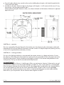
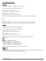
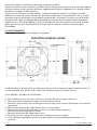
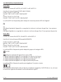
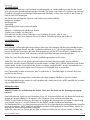
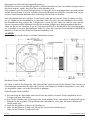
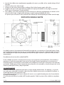
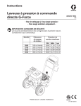
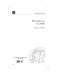
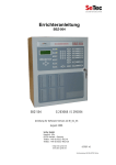
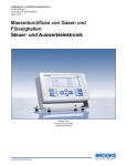
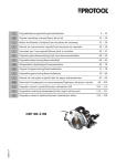
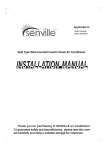
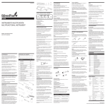
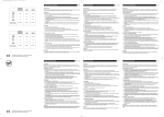
Technical Manual for the call points SM87BG/PB Exd versions Техническое руководство к извещателям версий SM87BG/PB Manuel Technique pour les versions Exd SM87BG/PB de Points d’Appel Manuel Technische Anleitung für die Feuermelder SM87BG/PB Exd-Ausführungen Manual técnico de los pulsadores SM87BG/PB versiones Exd Please note that every care has been taken to ensure the accuracy of our technical manual. We do not, however, accept responsibility for damage, loss or expense result-ing from any error or omission. We reserve the right to make alterations in line with technical advances and industry standards. Для обеспечения максимальной точности нашего технического руководства были предприняты все возможные меры. Наша компания не несет ответственности за повреждения, ущерб или расходы, связанные с возможным наличием в нем ошибок или пропусков. Мы оставляем за собой право вносить в него изменения с учетом технического прогресса и изменения промышленных стандартов. Toutes les précautions ont été prises pour garantir la précision de cette notice technique. Toutefois, nous ne saurions accepter de responsabilité à l’égard des dégâts, pertes ou frais résultant d’une quelconque erreur ou omission. Nous nous réservons le droit d’apporter d’éventuelles modifications pouvant résulter de progrès techniques ou de l’évolution des normes industrielles. Wir möchten Sie darauf hinweisen, dass wir große Sorgfalt darauf verwendet haben, die Richtigkeit unserer technischen Anleitung zu gewährleisten. Wir übernehmen jedoch keine Verantwortung für Schäden, Verluste oder Kosten, die sich aus einem etwaigen Fehler oder einem Versäumnis ergeben. Änderungen die dem technischen Fortschritt bzw. neusten Industrienormen entsprechen, behalten wir uns vor. Tenga en cuenta que se han tomado todas las precauciones para garantizar la exactitud de nuestro manual técnico. No obstante, no nos responsabilizamos de daños, pérdidas o costes resultantes de cualquier error u omisión. Nos reservamos el derecho de realizar modificaciones en línea con los avances técnicos y las normas de la industria. © Cooper MEDC 2010 11/10 English 1.0 Introduction These manual fire alarm, emergency shutdown breakglass and pushbutton units have been designed for the most arduous environmental conditions. The units are both easy to install and maintain. A choice of either stainless steel or alloy makes the range suitable for both the offshore and onshore industries. The units are available with the following options and features: Lift flap Duty label Tag label Earth continuity via internal/external earth studs LED End of Line and Series resistors and diodes Switches (two switches, four poles maximum) M20 or M25 gland entries in a range of positions, with a maximum of four Optional momentary or latching with key reset actions 2.0 INSTALLATION General When installing and operating explosion-protected equipment, requirements for selection, installation and operation should be referred to e.g. IEE Wiring Regulations and the ‘National Electrical Code’ in North America. Additional national and/or local requirements may apply. Ensure that all nuts, bolts and fixings are secure. Ensure that only the correct listed or certified stopping plugs are used to blank off unused gland entry points and that the NEMA/IP rating of the unit is maintained. MEDC recommend the use of a sealing compound such as HYLOMAR PL32 on the threads of glands and stopping plugs in order to maintain the IP rating of the unit. These alarm call points are designed to be directly mounted using the 4 off ∅9mm holes in the base of the unit. Units may be mounted to vertical, horizontal or angled surfaces. The holes have been designed to accept an M8 screw or bolt. MEDC recommend the use of stainless steel screws. Cable Termination CAUTION: Before removing the cover assembly, ensure that the power to the unit is isolated. Unscrew and remove the 4 off M6 screws (5.0mm A/F hexagon key) holding the cover assembly to the base. Keep in a safe, accessible location. Twist the cover assembly gently clockwise and anti-clockwise, whilst pulling it away from the base. Remove to gain access to the interior. Cable termination should be in accordance with specifications applying to the required application. MEDC recommends that all cables and cores should be correctly identified. Please refer to the wiring diagram provided with the product. Ensure that only the correct listed or certified cable glands are used and that the assembly is shrouded and correctly earthed. All cable glands should be of an equivalent NEMA/IP rating to that of the call point and integrated with the unit such that this rating is maintained. The internal earth terminal, where fitted, must be used for the equipment grounding connection and the 11/10 © Cooper MEDC 2010 external terminal is for a supplementary bonding connection where local codes or authorities permit or require such a connection. Once termination is complete, carefully push the cover assembly back onto the base, avoiding damage to the mating surfaces. Ensure that the retaining strap is not trapped between the mating surfaces and that the o-ring is correctly seated in its groove. Ensure the retaining strap and wires are clear of the microswitch actuator and operating mechanism. Replace the 4 off M6 screws (5.0mm A/F hexagon key) into the holes in the cover assembly and tighten evenly. Ensure the maximum gap of 0.15mm is maintained between the cover and the base once assembled. 3.0 OPERATION The3.0 operating voltage of the unit is stated on the unit label. OPERATION The operating voltage of the unit is stated on the unit label. SM87BG GENERAL SM87BG GENERALARRANGEMENT ARRANGEMENT SM87GB units - operation SM87GB units - operation The unit is operated by breaking the glass element in the front of the cover using the hammer attached to the The unit is operated by breaking the glass element in the front of the cover using the hammer attached to the unit. If a lift flap has been specified, this will need to be raised first to gain access to the glass element. unit. If a lift flap has been specified, this will need to be raised first to gain access to the glass element. SM87BG unitunit - resetting procedure SM87BG - resetting procedure a. a. To replace the glass, a kitacontaining O-rings andand glass is provided. To replace the glass, kit containing O-rings glass is provided. Unscrew remove circular bezel front of the unit. b. b. Unscrew andand remove the the circular bezel on on thethe front of the unit. Remove the original O-rings glass ensure grooves in the bezel cover clean. c. c. Remove the original O-rings andand glass andand ensure thethe grooves in the bezel andand cover areare clean. Fit the larger O-ring groove cover. d. d. Fit the larger O-ring intointo thethe groove onon thethe cover. Fit the smaller O-ring groove underside of the bezel:e. e. Fit the smaller O-ring intointo thethe groove on on thethe underside of the bezel:i. Offer the O-ring up to the groove. i. Offer the O-ring up to the groove. ii. Place thumbs of both hands side by side onto the O-ring ii. Place iii. thumbs of the both handsdown side into by side onto thecircumference O-ring Press O-ring the groove maintaining even pressure, forcing the O-ring iii. Press the O-ring into the groove circumference maintaining even pressure, forcing the O-ring into into thedown groove. the groove. iv. The O-ring should be fully seated in the groove and not fall out when fitting the bezel to the cover. iv. The O-ring should bethe fully seated the groove and not fall out when fitting the bezel to the cover. v. Centralise new glassinelement on the cover f. Place the position v. Centralise thenew newglass glasselement elementinto on the coveron the cover and assemble the bezel over the top of the glass element. f. Place the new glass element into position on the cover and assemble the bezel over the top of the glass g. Ensure the glass element stays central on the cover by holding down the glass with thumb through the element. hole in the centre of the bezel. h. Carefully use the glass element to depress the plunger until the glass is in full contact with the cover11/10 O© Cooper MEDC 2010 ring. Ensure there is an even gap around the glass. Without allowing the glass element to move, screw down the bezel until the bottom of the bezel is tightened against the cover. g. Ensure the glass element stays central on the cover by holding down the glass with thumb through the hole in the centre of the bezel. h. Carefully use the glass element to depress the plunger until the glass is in full contact with the cover O-ring. Ensure there is an even gap around the glass. Without allowing the glass element to move, screw down the bezel until the bottom of the bezel is tightened 3.0 OPERATION against the cover. The operating voltage of the unit is stated on the unit label. SM87PB GENERAL ARRANGEMENT SM87BG GENERAL ARRANGEMENT SM87GB units - operation SM87PB units - operation The unit operatedbybylifting breaking the on glass frontthen of the cover using hammer attached to the The unit is is operated the flap theelement front of in thethe cover, depressing thethe steel actuator underneath. unit. If a liftonflap thisactuator will needwill to be raised first to access toposition the glass element. Depending thehas unitbeen type specified, ordered, the either remain in gain its depressed (latching versions) or return to its original position (momentary versions). SM87BG unit - resetting procedure SM87PB units - resetting procedure a. To replace the glass, a kit containing O-rings and glass is provided. b. Unscrew and remove the circular bezel on the front of the unit. On with athe latching thethe actuator remains its depressed To reset c. units Remove originalmechanism, O-rings andonce glassoperated, and ensure grooves in the in bezel and coverposition. are clean. d. call Fitpoint, the larger O-ring intothe thefront groove on cover the cover. the lift the flap on of the and insert the key (provided with the unit) into the slot in the e. face Fit the O-ringThe intokey theshould groovebe onturned the underside oflocate the bezel:front of smaller the actuator. slightly to it in the actuator and pulled back to the i. Offer thekey O-ring to be theremoved groove. and the flap lowered. initial position. The can up then ii. Place thumbs of both hands side by side onto the O-ring iii. Press the O-ring down into the groove circumference maintaining even pressure, forcing the O-ring 4.0 MAINTENANCE into the groove. During iv. the working lifeshould of the unit, it should little or and no maintenance. However, if abnormal or unusual The O-ring be fully seatedrequire in the groove not fall out when fitting the bezel to the cover. environmental conditions due to plant damage or accident etc., then visual inspection is recommended. v. Centralise the occur new glass element on the cover If the unit requires then only exterior a damp cloth to avoid electro-static charge build up. f. Place the newcleaning, glass element into clean position on thewith cover and assemble the bezel over the top of the glass If a unit fault should occur, then the unit can be repaired by MEDC. All parts of the unit are replaceable. element. g. Ensure theaglass element stays central theitcover by holding down the glass the If you acquired significant quantity of units,onthen is recommended that spares arewith alsothumb madethrough available. in theyour centre of the bezel. Pleasehole discuss requirements with the Technical Sales Engineers at MEDC. h. Carefully use the glass element to depress the plunger until the glass is in full contact with the cover Oring. Ensure there is an even gap around the glass. Without allowing the glass element to move, screw down the bezel until the bottom of the bezel is tightened against the cover. 11/10 © Cooper MEDC 2010 5.0 CERTIFICATION/APPROVALS IECEx units Certified to IEC 60079-0, IEC 60079-1 and IEC 60079-31 Ex d unit (IEC certification No. IECEx BAS 09.0060) Ex d IIC T6 (-55°C to +55°C) Gb Ex tb IIIC T85°C (-55°C to +55°C) Db IP66/IP67 or Ex d IIC T5 (-55°C to +70°C) Gb Ex tb IIIC T100°C (-55°C to +70°C) Db IP66/IP67 The IECEx certificate and product label carry the IECEx equipment protection level marking Gb Db Where: Gb signifies suitability for use in a Zone 1 surface industries area in the presence of gas. Db signifies suitability for use in a Zone 21 surface industries area in the presence of dust ATEX units Certified to EN60079-0, EN60079-1 and EN60079-31 Ex d unit (ATEX certification No. Baseefa03ATEX0075) Ex d IIC T6 (-55°C to +55°C) Gb Ex tb IIIC T85°C (-55°C to +55°C) Db IP66/IP67 or Ex d IIC T5 (-55°C to +70°C) Gb Ex tb IIIC T100°C (-55°C to +70°C) Db IP66/IP67 The ATEX certificate and product label carry the ATEX group and category marking: II 2 GD Where: Signifies compliance with ATEX II Signifies suitability for use in surface industries 2 Signifies suitability for use in a zone 1 area G Signifies suitability for use in the presence of gases D Signifies suitability for use in the presence of dust The ATEX certificate and product label also carry the following mark: 1180 This signifies unit compliance to the relevant European directives, in this case 94/9/EC, along with the number of the notified body issuing the EC type examination certificate. © Cooper MEDC 2010 11/10 русский 1.0 ВВЕДЕНИЕ Настоящие устройства ручной пожарной сигнализации, предусматривающие разбивание стекла и нажатие кнопки аварийного выключения, разработаны для самых тяжелых условий окружающей среды. Эти устройства легко и устанавливать, и обслуживать. Возможность выбора в качестве конструкционного материала нержавеющей стали или сплава позволяет использовать их в отраслях промышленности, где работы могут производиться как в морских условиях, так и на суше. Устройства выпускаются со следующими возможностями и функциями: Подъемный щиток Ярлык с рабочими характеристиками Этикетка с маркировкой Заземление при помощи внутренних/наружных заземляющих штырей СИД Конечные и добавочные резисторы и диоды Переключатели (два переключателя с числом полюсов до четырех) Сальниковые вводы размером M20 или M5 в положениях, максимальное число которых не превышает четырех Предусмотренные отдельным заказом кратковременные или фиксируемые действия c возвратом в исходное состояние с помощью ключа 2.0 УСТАНОВКА Общая информация Требования, предъявляемые к выбору, установке и эксплуатации взрывозащищенного оборудования, должны соответствовать «Нормативным требованиям к монтажу электрических схем Института инженеров-электриков (IEE)» и «Национальным электротехническим нормативам» для Северной Америки. Необходимо учитывать также наличие дополнительных федеральных и (или) местных требований. Проследите, чтобы все гайки, болты и крепления были надежно затянуты. Проследите, чтобы для заглушки неиспользуемых сальниковых вводов использовались только правильно каталогизированные или сертифицированные заглушки и чтобы был выдержан класс защиты NEMA/IP устройства. Компания MEDC рекомендует нанести герметик HYLOMAR PL32 на резьбу сальников и заглушек с целью сохранения класса защиты IP устройства. Данные тревожные извещатели рассчитаны на установку с использованием 4 отверстий размером ∅9 мм в базовой части устройства. Устройства могут монтироваться на вертикальных, горизонтальных поверхностях, а также на поверхностях, расположенных под углом к вертикали. Отверстия рассчитаны под винты или болты размером M8. MEDC рекомендует использовать винты из нержавеющей стали. Кабельный ввод ОСТОРОЖНО! Перед снятием узла крышки убедитесь в том, что питание устройства отключено. 11/10 © Cooper MEDC 2010 Выверните 4 винта M6 (размер зева шестигранного ключа — 5,0 мм), удерживая крышку в сборе на установочной поверхности. Храните их в безопасном, легкодоступном месте. Осторожно поворачивайте крышку в сборе по часовой стрелке и против нее, при этом вытаскивая ее из базовой части. Удалите ее, чтобы получить доступ к внутреннему пространству. Кабельный ввод должен соответствовать спецификациям, разработанным для конкретной прикладной задачи. MEDC рекомендует, чтобы все кабели и жилы кабелей были должным ��������� ���� ������ ��������������� �������������, ������������� образом идентифицированы. См. схему электропроводки, поставляемую вместе с изделием. ��� ���������� ���������� ������. MEDC �����������, ����� ��� Проследите, чтобы использовались только правильно каталогизированные или ������ � ���� ������� ���� ������� �������и����������������. ��. ����� сертифицированные кабельные уплотнения чтобы узел был экранирован и правильно ���������������, ������������ ������ � ��������. заземлен. ����������, ����� �������������� ������ классу ��������� Все кабельные уплотнения должны соответствовать защиты������������������ NEMA/IP извещателя и ��� ����������������� ��������� ���������� � ����� ���� ��� быть встроены в устройство, как того требует этот класс. ����������� � ��������� ��������. Внутренняя клемма заземления там, где она установлена, должна использоваться для ��� ��������� ���������� ������ ��������������� ������ ������ NEMA/IP заземления оборудования, а внешняя клемма — для дополнительного заземления там, где ���������� � ���� �������� � ����������, ��� ���� ������� ���� �����. местные законы������ или власти позволяют ���, или требуют наличия такого соединения. ���������� ���������� ��� ��� �����������, ������ По завершении заделки большой осторожностью поместите крышку в������ сборе обратно �������������� ���с ���������� ������������, � ������� — ��� на основание, стараясь���������� не повредить ���, сопрягающиеся поверхности. Проследите, ��������������� ��� ������� ������ ��� ������чтобы фиксирующая скоба не попала между сопрягающимися поверхностями и чтобы кольцевое ��������� ��� ������� ������� ������ ����������. �� ���������� ������� ������� ������������� ��������� ������ уплотнение правильно село в�свою канавку. Проследите, чтобы фиксирующая скоба� и����� ������� ���������, �� ��������� ������������� провода не�� задевали привод�������� микропереключателя и управляющий механизм.�����������. Установите 4 ����������, ����������� ����� �� ������ ����� �������������� винта размером����� M6 (размер зева шестигранного ключа — 5,0 мм) обратно в отверстия узла ������������� � ����� ��������� ���������� ��������� � ���� был крышки и равномерно их затяните. Проследите, чтобы между крышкой ���� и основанием �������.зазор ����������, ����������� ����� � ������� �� �������� выдержан величиной����� не более 0,15 мм. ������ ������������������ � ����������� ��������. ���������� 4 ����� �������� M6 (������ ���� ������������� ����� — 5,0 ��) ������� � 3.0 ЭКСПЛУАТАЦИЯ ��������� ���� ������ � ���������� �� ��������. ����������, ����� ����� Рабочее напряжение устройства приведено на его этикетке. ������� � ���������� ��� �������� ����� ��������� �� ����� 0,15 ��. ОБЩАЯ КОМПОНОВКА SM87BG 3.0 ������������ ������� ���������� ���������� ��������� �� ��� ��������. ����� ���������� SM87BG ���������� SM87GB — ������������ ��� ���������� ����������� ���������� ������� ������ � �������� ����� ©������ Cooper MEDC 2010 11/10 ��� ������ �������, ������������ � ����������. � ������ ���� ��� ������������ ��������� �����, ����� �������� ������ � ������, ����� ���������� �������������� �������. Устройства SM87GB — эксплуатация Для управления устройством необходимо разбить стекло в передней части крышки при помощи молотка, прилагаемого к устройству. В случае если был предусмотрен подъемный щиток, чтобы получить доступ к стеклу, щиток необходимо предварительно поднять. Устройство SM87BG — процедура сброса a. Для замены стекла поставляется комплект, содержащий кольцевые уплотнения и само стекло. b. Выверните и снимите круглую лицевую панель в передней части устройства. c. Снимите исходные кольцевые уплотнения и стекло и проследите, чтобы канавки в лицевой панели и крышке были чистыми. d. Установите кольцевое уплотнение большего размера в канавку на крышке. e. Установите кольцевое уплотнение меньшего размера в канавку на обратной стороне лицевой панели:i. Разместите кольцевое уплотнение на канавке. ii. Положите большие пальцы обеих рук рядом друг с другом на кольцевое уплотнение iii. Равномерно нажимая на кольцевое уплотнение по всему контуру, вставьте его в канавку. iv. Кольцевое уплотнение должно полностью сесть в канавку и не должно выпадать при установке лицевой панели на крышку. v. Отцентрируйте положение нового стекла на крышке f. Установите новое стекло в надлежащее положение на крышке, а поверх стекла установите лицевую панель. g. Обеспечьте центральное положение стекла на крышке, прижимая и удерживая его большим пальцем через отверстие в центре лицевой панели. h. Осторожно надавливайте стеклом на шток, пока оно не войдет в полный контакт с кольцевым уплотнением крышки. Проследите, чтобы зазор вокруг стекла был равномерным. Не сдвигая стекла, вворачивайте лицевую панель до тех пор, пока ее дно не будет прижато к крышке. ОБЩАЯ КОМПОНОВКА SM87PB ����� ���������� SM87PB 11/10 ���������� SM87PB — ������������ © Cooper MEDC 2010 ��� ���������� ����������� ���������� ������� �����, ������������� Устройства SM87PB — эксплуатация Для управления устройством необходимо поднять щиток, расположенный перед крышкой, и нажать на стальной пускатель, находящийся под ним. В зависимости от типа заказанного устройства пускатель либо останется в нажатом положении (версии с фиксацией пускателя), либо вернется в исходное (версии с кратковременным нажатием). Устройства SM87PB — процедура сброса В устройствах с механизмом фиксации нажатый пускатель остается в нажатом положении. Чтобы восстановить готовность извещателя, поднимите щиток на передней крышке и вставьте ключ (поставляется вместе с устройством) в щель на передней стороне пускателя. Ключ следует слегка повернуть, чтобы установить его в пускателе, затем потянуть назад и вернуться в исходное положение. Затем можно извлечь ключ и опустить щиток. 4.0 ТЕХОБСЛУЖИВАНИЕ В течение всего срока службы устройству необходимо минимальное техобслуживание или вообще не требуется никакого техобслуживания. Однако, если, например, из-за повреждения или аварии установки возникают аномальные или необычные условия окружающей среды, рекомендуется производить визуальный осмотр. Если устройство нуждается в очистке, производите ее только для внешней его поверхности, используя для этого кусок влажной ткани во избежание накопления электростатического заряда. Если в работе устройства происходят сбои, его можно отремонтировать в компании MEDC. Может быть заменена любая деталь устройства. Если вы приобретаете большое количество устройств, рекомендуется иметь необходимый доступ к соответствующим запасным частям. Обсудите свои требования с инженерами службы сбыта компании MEDC. 5.0 СЕРТИФИКАЦИЯ/АТТЕСТАЦИЯ Устройства класса IECEx Сертифицированы на соответствие стандартам IEC 60079-0, IEC 60079-1 и IEC 60079-31 Устройство Ex d (сертификация IEC № IECEx BAS 09.0060) Ex d IIC T6 (от -55 до +55 °C) Gb Ex tb IIIC T85 °C (от -55 до +55 °C) Db IP66/IP67 или Ex d IIC T5 (от -55 до +70 °C) Gb Ex tb IIIC T100 °C (от -55 до +70 °C) Db IP66/IP67 В сертификате IECEx и на этикетке изделия содержится маркировка IECEx уровня защиты оборудования Gb Db Где: Gb означает возможность применения в наземных промышленных условиях Зоны 1 в присутствии газа. Db означает возможность применения в наземных промышленных условиях Зоны 21 в присутствии пыли © Cooper MEDC 2010 11/10 Устройства класса ATEX: Сертифицированы на соответствие стандартам EN60079-0, EN60079-1 и EN60079-31 Устройство Ex d (сертификация ATEX № Baseefa03ATEX0075) Ex d IIC T6 (от -55 до +55 °C) Gb Ex tb IIIC T85 °C (от -55 до +55 °C) Db IP66/IP67 или Ex d IIC T5 (от -55 до +70 °C) Gb Ex tb IIIC T100 °C (от -55 до +70 °C) Db IP66/IP67 В сертификате ATEX и на этикетке изделия содержится маркировка, характеризующая группу и категорию ATEX: II 2 GD Где: означает соблюдение требований ATEX II означает возможность использования в наземных промышленных условиях 2 означает возможность использования в условиях Зоны 1 G означает возможность использования в присутствии газов D означает возможность использования в присутствии пыли В сертификате ATEX и на этикетке изделия имеется также следующая отметка: 1180 Она означает соответствие устройства имеющим отношение к данному вопросу европейским директивам, в данном случае директиве 94/9/EC, и содержит количество уполномоченных органов, выпускающих свидетельство о проверке образца Европейского сообщества. 11/10 © Cooper MEDC 2010 Francais 1.0 INTRODUCTION Ces alarmes incendie, brise-vitres d’arrêt d’urgence et boutons d’arrêt manuels ont été conçus pour fonctionner dans les conditions environnementales les plus extrêmes. Ces unités sont faciles à installer et à entretenir. Un choix entre un alliage en aluminium de catégorie marine ou en acier inoxydable rendent la gamme appropriée pour l’usage en mer ou sur terre. Les unités sont disponibles avec les options et fonctionnalités suivantes : Volet soulevable Etiquette de fonction Etiquette d’identification Continuité de mise à la masse à travers des bornes internes et externes DEL Résistances et diodes Fin de Ligne et Série Commutateurs (deux commutateurs, quatre pôles maximum) Entrées de presse-étoupes M20 ou M5 dans une série de positions, au maximum 4 Loquet ou verrou facultatif avec réinitialisation par clé 2.0 INSTALLATION Généralités Lors de l’installation et de la mise en service d’un appareil protégé contre les explosions, les spécifications de sélection, d’installation et de fonctionnement doivent être consultées, par exemple les règlements de l’IEE en matière de câblage et le « National Electric Code » en Amérique du Nord. Des spécifications nationales et/ou locales additionnelles peuvent s’appliquer. Assurez-vous que tous les écrous, les boulons et les attaches sont bien fixés. Assurez-vous que seuls les bouchons listés ou certifiés sont utilisés pour neutraliser les presse-étoupes inutilisés, et que l’indice NEMA/IP de l’unité est maintenu. MEDC recommande l’application d’un composé d’étanchéité tel que le HYLOMAR PL32 sur les fils des presse-étoupes et des bouchons afin de maintenir l’indice IP de l’unité. Ces points de déclenchement d’alarme sont conçus pour être directement montés via 4 trous de fixation de ∅9 mm à la base de l’unité. Les unités peuvent être montées sur des surfaces verticales, horizontales ou inclinées. Les trous ont été conçus pour accepter une vis ou un boulon M8. MEDC recommande l’usage de vis en acier inoxydable. Terminaisons des câbles AVERTISSEMENT : Avant d’enlever le couvercle, assurez-vous que l’alimentation est débranchée. Dévissez et enlevez les 4 vis M6 (clé hexagonale A/F de 5,0 mm) retenant le couvercle à la base. Gardez les vis dans un endroit accessible et sûr. Tournez doucement le couvercle dans les deux sens tout en l’éloignant de la base du boîtier. Soulevez-le pour accéder à l’intérieur. Les terminaisons des câbles doivent être conformes aux spécifications relatives au domaine d’application voulu. MEDC recommande que tous les câbles et les âmes soient correctement identifiés. Veuillez vous référer au schéma de câblage fourni avec le produit. Assurez-vous que seuls les presse-étoupes correctement listés ou certifiés sont utilisés et que l’ensemble est fermé et correctement relié à la masse. Tous les presse-étoupes doivent posséder un indice NEMA/IP équivalent à celui du point de déclenchement et © Cooper MEDC 2010 11/10 doivent être intégrés à l’unité d’une manière qui maintienne cet indice. La borne de masse interne, lorsqu’elle est installée, doit être utilisée pour la connexion à la masse de l’appareil, et la borne externe sert de connexion de liaison supplémentaire lorsque les règlements ou les autorités locales permettent ou exigent une telle connexion. Une fois que les terminaisons ont été installées, replacez doucement le couvercle sur le boîtier en évitant d’abîmer les surfaces de contact. Assurez-vous que la lanière de fixation n’est pas bloquée entre les surfaces de contact et que le joint torique est correctement positionné dans sa cannelure. Assurez-vous que la lanière de fixation et les câbles sont dégagés de la commande de micro contact et du dispositif de fonctionnement. Replacez les 4 vis M6 (clé hexagonale A/F de 5,0 mm) dans les trous du couvercle et resserrez de manière Replacez les 4 vis M6que (clél’écart hexagonale 5,0mm mm) dans trous du couvercle resserrez de manière égale. Assurez-vous maximalA/F de de 0,15 entre le les couvercle et la base est et maintenu après égale. Assurez-vous que l’écart maximal de 0,15 mm entre le couvercle et la base est maintenu après l’assemblage. l’assemblage. 3.0 FONCTIONNEMENT 3.0 FONCTIONNEMENT La tension nominale de l’unité est indiquée sur l’étiquette. La tension nominale de l’unité est indiquée sur l’étiquette. DISPOSITION GENERALE GENERALE SM87BG DISPOSITION SM87BG Unités SM87BG - fonctionnement Unités SM87BG - fonctionnement L’unité fonctionne en brisant la vitre sur la face avant du couvercle au moyen du marteau attaché à l’unité. SI L’unité la vitre sur ladevra face avant du couvercle au moyen du marteau un voletfonctionne soulevableena brisant été spécifié, celui-ci être soulevé pour pouvoir accéder à la vitre.attaché à l’unité. SI un volet soulevable a été spécifié, celui-ci devra être soulevé pour pouvoir accéder à la vitre. Unités SM87BG - procédure de réinitialisation Unités SM87BG - procédure de réinitialisation a. a. b. b. c. c. Pour remplacer la vitre, une trousse est fournie, contenant des joints toriques et des vitres. Pour remplacer la vitre, une trousse est fournie, contenant des joints toriques et des vitres. Dévissez et enlevez le panneau circulaire sur la face avant de l’unité. Dévissez et enlevez le panneau circulaire sur la face avant de l’unité. Enlevez les que lesles rainures du du panneau et du Enlevez les joints jointstoriques toriquesetetlalavitre vitred’origine d’origineetetassurez-vous assurez-vous que rainures panneau et couvercle du sont propres. couvercle sont propres. d. Placez Placez le d. le joint joint torique torique le le plus pluslarge large dans danslalarainure rainuresur surlelecouvercle. couvercle. e. Placez Placez le : : e. le joint joint torique torique le le plus pluspetit petitdans danslalarainure rainuresur surlalaface faceinterne internedudupanneau panneau i. Positionnez le joint le torique dans ladans rainure. i. Positionnez joint torique la rainure. ii. Placez les deux de chaque côté du joint. ii. Placez lespouces deux pouces de chaque côté du joint. iii. Pressez le joint le vers l’intérieur de la rainure en maintenant une pression égale. égale. iii. Pressez joint vers l’intérieur de la rainure en maintenant une pression joint doit être complètement ne paslors tomber lors du positionnement du sur panneau sur iv. Leiv.jointLedoit être complètement encastréencastré et ne pasettomber du positionnement du panneau le le couvercle. couvercle. v. Centrez la nouvelle vitre sur le couvercle. 11/10 © Cooper MEDC 2010 f. Placez la nouvelle vitre en position sur le couvercle et assemblez le panneau par dessus la vitre. g. Assurez-vous que la vitre reste au centre du couvercle en maintenant celle-ci avec le pouce passé à travers le trou au centre du panneau. v. Centrez la nouvelle vitre sur le couvercle. f. Placez la nouvelle vitre en position sur le couvercle et assemblez le panneau par dessus la vitre. g. Assurez-vous que la vitre reste au centre du couvercle en maintenant celle-ci avec le pouce passé à travers le trou au centre du panneau. h. Utilisez la vitre avec précaution pour dépressuriser le piston jusqu’à ce qu’elle soit en contact complet avec le joint torique du couvercle. Assurez-vous qu’il y a un écart égal tout autour de la vitre. Sans laisser la vitre bouger, vissez le panneau jusqu’à ce que sa partie inférieure soit resserrée contre le couvercle. DISPOSITION GENERALE SM87PB DISPOSITION GENERALE SM87PB Unités SM87PB - fonctionnement Unités SM87PB - fonctionnement L’unité fonctionne suite au soulèvement du couvercle et à la dépressurisation de l’actionneur en acier situé desL’unité fonctionne aucommandé, soulèvement du couvercle et à la de l’actionneur acier situéou sous. Selon le type suite d’unité l’actionneur restera endépressurisation position dépressurisée (versions en avec loquet) dessous. Selon le type d’unité commandé, l’actionneur restera en position dépressurisée (versions avec retournera à sa position initiale (versions avec momentum). loquet) ou retournera à sa position initiale (versions avec momentum). Unités UnitésSM87PB SM87PB- -procédure procédurede deréinitialisation réinitialisation Sur dede verrouillage, Surles lesunités unitéspossédant possédantununmécanisme mécanisme verrouillage,l’actionneur l’actionneurreste resteenenposition positionune unefois foisactionné. actionné.Pour Pour réinitialiser réinitialiser le le point point de de déclenchement, déclenchement,soulevez soulevezlelecouvercle couverclede delalaface faceavant avantde del’unité l’unitéetetinsérez insérezlalaclé clé(fournie (fournie avecdans l’unité) dansde la la fente la face de l’actionneur. Laêtre clé tournée doit êtrelégèrement tournée légèrement pour la avec l’unité) la fente facedeavant de avant l’actionneur. La clé doit pour la loger logerl’actionneur, dans l’actionneur, puis remise sa position cléensuite peut ensuite être retirée et le volet dans puis remise dans sadans position initiale.initiale. La clé La peut être retirée et le volet rabaissé. rabaissé. 4.0 ENTRETIEN 4.0 ENTRETIEN L’unité ne devrait exiger que très peu, ou pas, d’entretien au cours de sa durée de vie. Toutefois, si des conditions environnementales anormales ou inhabituelles se produisent suite à un accident d’usine etc., une inspecL’unité ne devrait exiger que très peu, ou pas, d’entretien au cours de sa durée de vie. Toutefois, si des tion visuelleenvironnementales de l’appareil est recommandée. conditions anormales ou inhabituelles se produisent suite à un accident d’usine etc., une Siinspection l’unité doit être nettoyée, ne nettoyez que l’extérieur avec un chiffon humide pour éviter le développement de visuelle de l’appareil est recommandée. charges Si l’unitéélectrostatiques. doit être nettoyée, ne nettoyez que l’extérieur avec un chiffon humide pour éviter le développement Sideune unité tombe en panne, celle-ci pourra être réparée par MEDC. Tous les composants de l’unité sont charges électrostatiques. Si une unité tombe en panne, celle-ci pourra être réparée par MEDC. Tous les composants de l’unité sont remplaçables. Siremplaçables. vous avez acquis de nombreuses unités, il est recommandé de commander des pièces de rechange. Veuillez Si vous acquis de nombreuses unités, il est recommandé de commander faire partavez de vos spécifications aux ingénieurs technico-commerciaux de MEDC.des pièces de rechange. Veuillez faire part de vos spécifications aux ingénieurs technico-commerciaux de MEDC. © Cooper MEDC 2010 11/10 5.0 CERTIFICATION/HOMOLOGATIONS Unités IECEx Certifiées aux normes IEC 60079-0, IEC 60079-1 et IEC 60079-31 Unité Ex d (n° de certification IEC IECEx BAS 09.0060) Ex d IIC T6 (-55°C à +55°C) Gb Ex-tb IIIC T 85°C (-55°C à +55°C) Db IP66/IP67 ou Ex-d IIC T5 (-55°C à +70°C) Gb Ex-tb IIIC T 100°C (-55°C à +70°C) Db IP66/IP67 Le certificat IECEx et l’étiquette de produit indiquent le niveau de protection IECEx de l’appareil Gb Db Où : Gb indique l’aptitude de l’appareil à un usage dans les industries à ciel ouvert de type Zone 1 avec présence de gaz. Db indique l’aptitude à un usage dans les industries à ciel ouvert de type Zone 21 avec présence de poussière Unités ATEX Certifiées aux normes EN 60079-0, EN 60079-1 et EN 60079-31 Unité Ex d (n° de certification ATEX Baseefa03ATEX0075) Ex d IIC T6 (-55°C à +55°C) Gb Ex-tb IIIC T 85°C (-55°C à +55°C) Db IP66/IP67 ou Ex-d IIC T5 (-55°C à +70°C) Gb Ex-tb IIIC T 100°C (-55°C à +70°C) Db IP66/IP67 Le certificat ATEX et l’étiquette de produit indiquent le groupe et la catégorie ATEX : II 2 GD Où : II 2 G D indique la conformité de l’appareil aux normes ATEX indique l’aptitude de l’appareil à un usage dans les industries à ciel ouvert indique l’aptitude de l’appareil à un usage dans un secteur de type zone 1 indique l’aptitude de l’appareil à un usage en présence de gaz indique l’aptitude de l’appareil à un usage en présence de poussière Le certificat ATEX et l’étiquette du produit portent également l’inscription suivante : 1180 Cela indique la conformité de l’unité aux directives européennes appropriées, 94/9/EC dans ce cas, ainsi que le numéro de l’organisme distribuant le certificat d’examen de type EC. 11/10 © Cooper MEDC 2010 Deutsch 1.0 EINFÜHRUNG Diese manuellen Glasbruch- und Drucktaster-Handfeuermelder zur Notabschaltung wurden für den Einsatz unter schwierigsten Umgebungsbedingungen entwickelt. Die Geräte sind einfach zu installieren und wartungsfreundlich. Hergestellt aus beständigen Legierungen oder Edelstahl, ist diese Serie sowohl für den Einsatz an Land als auch auf See geeignet. Die Geräte sind mit folgenden Optionen und Funktionsmerkmalen erhältlich: Klappe zum Anheben Betriebsartetikett Typenschild Erdverbindung über interne/externe Erdstifte LED Abschluss- und Reihenwiderstände und -dioden Schalter (zwei Schalter, vier Pole max.) M20 oder M5 Anschlussstutzen-Öffnungen in verschiedenen Positionen, max. 4 Stück Optionaler Tast- oder Einrast-Mechanismus für Drucktaste; Rückstellung erfolgt über Schlüssel 2.0 INSTALLATION Allgemeines Bei Installation und Betrieb explosionsgeschützter elektrischer Einrichtungen sind die entsprechenden landesspezifischen Regelungen betreffs Auswahl, Installation und Betrieb (z. B.: „IEE Wiring Regulations“ [Installationsvorschriften der Vereinigung Britischer Elektroingenieure] und die NEC-Vorschriften in Nordamerika) zu beachten. Zusätzlich können auch nationale und/oder lokale Bestimmungen Anwendung finden. Stellen Sie sicher, dass alle Muttern, Schrauben und Befestigungselemente fest sitzen. Stellen Sie sicher, dass nur die korrekt gelisteten oder zertifizierten Verschlussstopfen zum Verschließen unbenutzter Anschlussstutzen-Öffnungen verwendet werden, und dass die IP-/NEMA-Schutzklasse der Einheit erhalten bleibt. Um die IP-Schutzklasse der Einheit zu erhalten, empfiehlt MEDC, an den Gewinden der Anschlussstutzen und Verschlussstopfen eine Dichtmasse wie HYLOMAR PL32 zu verwenden. Diese Feuermelder wurden so konstruiert, dass sie mithilfe der 4 ∅9 mm-Bohrungen im Unterteil der Einheit montiert werden können. Die Geräte können an waagrechten, senkrechten oder abgeschrägten Oberflächen montiert werden. Die Befestigungsbohrungen wurden für M8 Schrauben oder -Bolzen konstruiert. MEDC empfiehlt die Verwendung von Edelstahlschrauben. Kabelendverschluss VORSICHT: Stellen Sie vor Entfernung des Deckels sicher, dass das Gerät von der Spannungsversorgung isoliert ist. Lösen und entfernen Sie die vier M6 Schrauben (5 mm A/F Sechskantstiftschlüssel), mit denen die Deckel-Baugruppe am Unterteil befestigt ist. Bewahren Sie die Schrauben sicher und leicht erreichbar auf. Drehen Sie den Deckel vorsichtig im Uhrzeigersinn und gegen den Uhrzeigersinn und ziehen ihn gleichzeitig vom Unterteil weg, bis er sich löst. Entfernen Sie den Deckel, um das Geräteinnere freizulegen. Der Kabelendverschluss ist in Übereinstimmung mit den für die entsprechende Anwendung geltenden Spezifikationen durchzuführen. MEDC empfiehlt, alle Kabel und Adern ordnungsgemäß zu kennzeichnen. Nutzen Sie dazu den mit dem Produkt gelieferten Schaltplan. Stellen Sie sicher, dass nur korrekt gelistete oder zertifizierte Anschlussstutzen benutzt werden, und dass die © Cooper MEDC 2010 11/10 Baugruppe ummantelt und ordnungsgemäß geerdet ist. Alle Anschlussstutzen müssen über die gleiche IP-/NEMA-Schutzklasse wie der Feuermelder verfügen und so in das Gerät integriert werden, dass diese Klasse aufrechterhalten wird. Falls eingebaut, muss die interne Erdungsklemme zur Erdung des Ausrüstungsgegenstands verwendet werden, und die externe Klemme ist für eine zusätzliche Masseverbindung bestimmt, die dort verwendet wird, wo die örtlichen Vorschriften oder Behörden diese Verbindung zulassen oder vorschreiben. Nach dem Kabelendverschluss drücken Sie den Deckel wieder auf das Unterteil. Gehen Sie dabei vorsichtig vor, umdem Schäden an den Kontaktflächen zuden vermeiden. Stellen sicher, dassGehen das Halteband zwischen Nach Kabelendverschluss drücken Sie Deckel wieder aufSie das Unterteil. Sie dabei nicht vorsichtig den und dass der O-Ring korrekt Stellen in seiner sitzt. Stellen Sie weiterhin sicher, dass die vor,Kontaktflächen um Schäden anliegt, den Kontaktflächen zu vermeiden. SieNut sicher, dass das Halteband nicht zwischen internen Leitungen und nicht das Mikroschalter-Stellglied und -Betätigungselement berühren. den Kontaktflächen liegt,das undHalteband dass der O-Ring korrekt in seiner Nut sitzt. Stellen Sie weiterhin sicher, dass die Setzen die vier und M6 Schrauben (5 mm in die Bohrlöcher der DeckelinternenSie Leitungen das Halteband nichtA/F dasSechskantstiftschlüssel) Mikroschalter-Stellglied und -Betätigungselement berühren. Baugruppe ein, und ziehen Sie sie dann gleichmäßig an. Stellen Sie sicher, dass nach dem Zusammenbau Setzen Sie die vier M6 Schrauben (5 mm A/F Sechskantstiftschlüssel) in die Bohrlöcher der Deckel-Baugruppe ein Abstand von maximal 0,15 mm zwischen Deckel und Unterteil beibehalten wird. ein, und ziehen Sie sie dann gleichmäßig an. Stellen Sie sicher, dass nach dem Zusammenbau ein Abstand von maximal 0,15 mm zwischen Deckel und Unterteil beibehalten wird. 3.0 BETRIEB Die Betriebsspannung des Geräts ist auf dem Geräteetikett vermerkt. 3.0 BETRIEB Die Betriebsspannung des Geräts ist SM87BG auf dem Geräteetikett vermerkt. ÜBERSICHTSZEICHNUNG SM87BG ÜBERSICHTSZEICHNUNG Betrieb des Geräts SM87GB Betrieb des Geräts SM87GB Das Gerät wird durch Einschlagen der Glasscheibe auf der Vorderseite des Deckels betätigt. Dazu wird der DasGerät Gerätbefestigte wird durch Einschlagen der Wenn Glasscheibe auf der deszum Deckels betätigt. Dazu wirdist, dermuss am am Hammer benutzt. das Gerät mitVorderseite einer Klappe Anheben ausgestattet Geräterst befestigte Hammer benutzt. Gerät mit einer Klappe zum Anheben ausgestattet ist, muss diese diese angehoben werden, umWenn an diedas Glasscheibe zu gelangen. erst angehoben werden, um an die Glasscheibe zu gelangen. Rückstellung des Geräts SM87BG Rückstellung des Geräts SM87BG a. Zur Erneuerung der Glasscheibe nach einem Einsatz des Melders, benutzen Sie das mitgelieferte Set aus a. Zur Erneuerung der Glasscheibe nach einem Einsatz des Melders, benutzen Sie das mitgelieferte Set aus O-Ringen und neuer Glasscheibe. neuer Glasscheibe. b. O-Ringen Lösen Sie und die Schrauben des Deckelrings an der Vorderseite des Geräts, und nehmen Sie den Deckelring ab. c. Entfernen SieSchrauben die originalen O-Ringe und und stellen Sie sicher, dass dieSie Nuten Blende und b. Lösen Sie die des Deckelrings andas der Glas Vorderseite des Geräts, und nehmen den in Deckelring ab. sauber sind. c. Deckel Entfernen Sie die originalen O-Ringe und das Glas und stellen Sie sicher, dass die Nuten in Blende und d. Legen den sind. größeren O-Ring in die Deckelnut ein. DeckelSie sauber e. Sie den dengrößeren kleinerenO-Ring O-Ringinindie dieDeckelnut Nut auf der d. Legen Legen Sie ein.Unterseite des Deckelrings ein: i. Legen den kleineren aufauf dieder Nut. e Legen Sie denSie kleineren O-Ring O-Ring in die Nut Unterseite des Deckelrings ein: ii. Legen beide Daumen nebeneinander auf den O-Ring. i. Legen Sie denSie kleineren O-Ring auf die Nut. iii. Drücken Sie den O-Ring mit gleichmäßigem Druck ringsum in die Nut. iv. Der O-Ring muss vollständig in der Nut sitzen und darf nicht herausfallen, wenn der Deckelring auf 11/10 © Cooper MEDC 2010 den Deckel gelegt wird. v. Zentrieren Sie die neue Glasscheibe auf dem Deckel. f. Setzen Sie die neue Glasscheibe in den Deckel ein und montieren Sie den Deckelring über der ii. Legen Sie beide Daumen nebeneinander auf den O-Ring. iii. Drücken Sie den O-Ring mit gleichmäßigem Druck ringsum in die Nut. iv. Der O-Ring muss vollständig in der Nut sitzen und darf nicht herausfallen, wenn der Deckelring auf den Deckel gelegt wird. v. Zentrieren Sie die neue Glasscheibe auf dem Deckel. f. Setzen Sie die neue Glasscheibe in den Deckel ein und montieren Sie den Deckelring über der Glasscheibe. g. Stellen Sie sicher, dass die Glassscheibe mittig auf dem Deckel bleibt, indem Sie sie mit dem durch den Deckelring gestreckten Daumen an ihrem Platz halten. h. Benutzen Sie dann vorsichtig die Glassscheibe, um den Kolben so weit hineinzudrücken, dass die Glass cheibe vollständigen Kontakt mit dem Deckel-O-Ring hat. Stellen Sie sicher, dass ringsum um die Glass cheibe ein gleich großer Zwischenraum frei bleibt. Schrauben Sie den Deckelring fest, ohne der Glasscheibe eine Bewegung zu ermöglichen, bis das Unterteil des Deckelrings am Deckel fest anliegt. SM87PB SM87PBÜBERSICHTSZEICHNUNG ÜBERSICHTSZEICHNUNG Betrieb des Geräts SM87PB Betrieb des Geräts SM87PB Man benutzt das Gerät, indem die Klappe an der Vorderseite des Deckels angehoben und dann das darunter Man benutzt das Gerät, indem die Klappe an der Vorderseite des Deckels angehoben und dann das darunter befindliche Stellglied Stellglied aus Ausführung bleibt das Stellglied entweder in in befindliche aus Stahl Stahlbetätigt betätigtwird. wird.Je Jenach nachbestellter bestellter Ausführung bleibt das Stellglied entweder seiner aktivierten/niedergedrückten Stellung (Einrast-Version) oder kehrt in seine Ausgangsstellung zurück seiner aktivierten/niedergedrückten Stellung (Einrast-Version) oder kehrt in seine Ausgangsstellung zurück (Tast-Version). (Tast-Version). Rückstellung des Rückstellung desGeräts GerätsSM87PB SM87PB Bei den den Geräten Geräten mit Stellglied nach Betätigung in der aktivierten/niedergeBei mit Einrast-Mechanismus Einrast-Mechanismusverbleibt verbleibtdas das Stellglied nach Betätigung in der aktivierten/niedergedrückten Stellung. Um den Feuermelder heben Sie die Klappe an der drückten Stellung. Um den Feuermelder zurückzustellen, hebenzurückzustellen, Sie die Klappe an der Vorderseite des Deckels Vorderseite desden Deckels an und dengeliefert) Schlüssel Gerät geliefert) in den Schlitz an derDer an und stecken Schlüssel (mitstecken dem Gerät in (mit den dem Schlitz an der Vorderseite des Stellglieds. Vorderseite desleicht Stellglieds. Schlüssel sollte leicht gedreht werden, umkann ihn ins zu stecken. Dann Schlüssel sollte gedrehtDer werden, um ihn ins Stellglied zu stecken. Dann es Stellglied in die Ausgangsposition kann es in die Ausgangsposition zurückbewegt werden. kann derund Schlüssel wieder herausgezogen zurückbewegt werden. Danach kann der Schlüssel wiederDanach herausgezogen die Klappe heruntergeklappt und die Klappe heruntergeklappt werden. werden. 4.0 INSTANDHALTUNG Während des Arbeitslebens des Geräts sollten nur geringe oder gar keine Instandhaltungsarbeiten erforderlich sein. Wenn allerdings aufgrund eines Anlagenschadens oder Unfalls etc. ungewöhnliche © Cooper MEDC 2010 11/10 Umgebungsbedingungen auftreten, wird eine Sichtprüfung empfohlen. Wenn das Gerät gereinigt werden muss, reinigen Sie es nur von außen mit einem feuchten Tuch, um eine elektrostatische Aufladung zu vermeiden. 4.0 INSTANDHALTUNG Während des Arbeitslebens des Geräts sollten nur geringe oder gar keine Instandhaltungsarbeiten erforderlich sein. Wenn allerdings aufgrund eines Anlagenschadens oder Unfalls etc. ungewöhnliche Umgebungsbedingungen auftreten, wird eine Sichtprüfung empfohlen. Wenn das Gerät gereinigt werden muss, reinigen Sie es nur von außen mit einem feuchten Tuch, um eine elektrostatische Aufladung zu vermeiden. Sollte ein Fehler im Gerät auftreten, kann es von MEDC instandgesetzt werden. Alle Bauteile können ersetzt werden. Wenn Sie größere Stückzahlen erworben haben, wird die Lagerhaltung von Ersatzaggregaten empfohlen. Bitte besprechen Sie Ihren Ersatzteilbedarf mit den Vertriebsingenieuren von MEDC. 5.0 ZERTIFIZIERUNG / GENEHMIGUNGEN IECEx Einheiten Zertifiziert gemäß IEC 60079-0, IEC 60079-1 und IEC 60079-31 Ex d Einheit (IEC-Zertifizierungsnummer IECEx BAS 09.0060) Ex d IIC T6 (-55°C bis +55°C) Gb Ex tb IIIC T85°C (-55°C bis +55°C) Db IP66/IP67 oder Ex d IIC T5 (-55°C bis +70°C) Gb Ex tb IIIC T100°C (-55°C bis +70°C) Db IP66/IP67 Das IECEx-Zertifikat und das Produktetikett tragen die IECEx-Kennzeichnung zum Geräte-Schutzniveau: Gb Db Dabei steht: Gb für die Eignung zur Verwendung in einem Bereich der „Zone 1“, Übertageindustrien in gashaltigen Bereichen. Db für die Eignung zur Verwendung in einem Bereich der „Zone 21“, Übertageindustrien in staubhaltigen Bereichen. 11/10 © Cooper MEDC 2010 ATEX Einheiten Zertifiziert gemäß EN 60079-0, EN 60079-1 und EN 60079-31 Ex d Einheit (ATEX-Zertifizierungsnummer Baseefa03ATEX0075) Ex d IIC T6 (-55°C bis +55°C) Gb Ex tb IIIC T85°C (-55°C bis +55°C) Db IP66/IP67 oder Ex d IIC T5 (-55°C bis +70°C) Gb Ex tb IIIC T100°C (-55°C bis +70°C) Db IP66/IP67 Das ATEX-Zertifikat und das Produktetikett tragen die ATEX-Gruppen und -Kategoriekennzeichnung: II 2 GD Dabei steht: II 2 G D für die Einhaltung der ATEX-Vorschriften, für die Eignung zur Verwendung in Übertageindustrien, für die Eignung zur Verwendung in einem Bereich der „Zone 1“, für die Eignung zur Verwendung in gashaltigen Bereichen, für die Eignung zur Verwendung in staubhaltigen Bereichen. Das ATEX-Zertifikat und das Produktetikett tragen außerdem folgendes Zeichen: 1180 Dieses Zeichen bedeutet, dass das Gerät die anzuwendenden EU-Richtlinien erfüllt, in diesem Fall 94/9/ EG. Außerdem gibt es die Nummer der registrierten Behörde an, die die EG-Baumusterprüfbescheinigung ausgefertigt hat. © Cooper MEDC 2010 11/10 Português 1.0 INTRODUCCIÓN Estas unidades de alarma contra incendios manual, desconexión de emergencia rompiendo un vidrio y botón pulsador han sido diseñadas para enfrentar las condiciones ambientales más arduas. Las unidades son fáciles de instalar y de mantener. La opción de acero inoxidable o aleación ofrece una variedad apta para el uso en industrias en tierra firme o en alta mar. Las unidades están disponibles con las siguientes opciones y características: Pestaña que se puede levantar Etiqueta de funciones Marbete Puesta a tierra a través de clavijas de conexión a tierra internas/externas LED Final de línea y resistencias eléctricas y diodos de serie Interruptores (dos interruptores, cuatro postes como máximo) Entradas de collarines M20 o M5 en varias posiciones, con un máximo de cuatro Acciones de reinicio opcionales momentáneas o de cerrojo con llave 2.0 INSTALACIÓN General Al instalar y poner en funcionamiento equipos con protección contra explosiones, se deberán consultar los requisitos para la selección, instalación y funcionamiento, por ejemplo, las normas de cableado del Instituto de Ingenieros Eléctricos (IEE, por sus siglas en inglés) y el Código Eléctrico Nacional (NEC, por sus siglas en inglés) de Norteamérica. Es posible que se apliquen otros requisitos nacionales o locales. Asegúrese de que todas las tuercas, los pernos y las fijaciones estén firmemente ajustados. Asegúrese de utilizar solamente los tapones de sellado correctos, enumerados o certificados, para obturar los puntos de entrada de los collarines que no se usen y también de que se mantenga la calificación NEMA/IP de la unidad. MEDC recomienda el uso de un compuesto sellador como HYLOMAR PL32 en las roscas de los collarines y en los tapones de sellado, para así mantener la calificación IP de la unidad. Estos pulsadores de alarma están diseñados para ser montados directamente a través de los 4 orificios de ∅9 mm que se encuentran en la base de la unidad. Las unidades se pueden montar en superficies verticales, horizontales o en ángulo. Los orificios han sido diseñados para aceptar pernos o tornillos M8. MEDC recomienda utilizar tornillos de acero inoxidable. Caja terminal PRECAUCIÓN: Antes de quitar la tapa, asegúrese de que la alimentación a la unidad esté aislada. Desatornille y quite los 4 tornillos M6 (5,0 mm de cabeza hexagonal A/F) mientras sostiene la tapa sobre la base. Guárdelos en un lugar seguro y accesible. Gire suavemente la tapa en sentido horario y antihorario, mientras tira de ella para sacarla de la base. Quítela para acceder al interior. La caja terminal debe cumplir con las especificaciones correspondientes a la aplicación solicitada. MEDC recomienda que todos los cables y conductores estén identificados correctamente. Consulte el diagrama de conexiones suministrado con el producto. Asegúrese de utilizar sólo los collarines correctos, enumerados o certificados y de que la unidad esté oculta y puesta a tierra correctamente. 11/10 © Cooper MEDC 2010 Todos los collarines de cables deben ser de una calificación NEMA/IP equivalente a la del pulsador y deben estar integrados con la unidad, de manera de mantener la calificación. El borne de puesta a tierra interno, cuando esté fijado, se debe utilizar para la conexión a tierra del equipo y el borne externo, para un empalme adicional, donde los códigos o autoridades locales permitan o exijan ese tipo de conexiones. Una vez finalizada la terminación, presione cuidadosamente la tapa sobre la base y evite dañar las superficies de acoplamiento. Asegúrese de que la correa de retención no quede atrapada entre las superficies de acoplamiento y de que la junta tórica esté apoyada correctamente sobre la ranura. Asegúrese de que la correa de retención y el cableado estén lejos del accionador del microinterruptor y del mecanismo de funcionamiento. Vuelva a colocar los 4 tornillos M6 (5,0 mm de cabeza hexagonal A/F) en los orificios de la tapa y ajústelos firme y uniformemente. Una vez armada, asegúrese de mantener el espacio máximo de 0,15 mm entre la tapa y la base. 3.0 FUNCIONAMIENTO El voltaje de funcionamiento de la unidad se indica enGENERAL la etiqueta.SM87PB DISPOSICIÓN DISPOSICIÓN GENERAL SM87BG Funcionamiento de unidades SM87PB Funcionamiento de unidades SM87GB levantando la pestaña que se encuentra en el frente de la tapa y luego La unidad se pone en funcionamiento presionando el accionador de acero que se encuentra debajo. Según el tipo de unidad solicitada, el La unidad sesepone en funcionamiento rompiendo el vidrio que sede encuentra frente a laatapa, con el martillo accionador mantendrá en la posición presionada (versiones cerrojo) o volverá su posición inicial adosado. se ha especificado una pestaña que se puede levantar, primero deberá levantar la pestaña para (versionesSimomentáneas). poder acceder al vidrio. Procedimiento de reinicio de la unidad SM87PB Procedimiento de reinicio de la unidad SM87BG En las unidades que tienen un mecanismo de cerrojo, una vez puestas en funcionamiento, el accionador se mantiene en la posición presionada. Para el pulsador, levante a. Para cambiar el vidrio, se suministra unreiniciar kit que contiene juntas tóricaslaypestaña vidrio. que se encuentra en el frente de la tapay equite inserte la llave (suministrada con la unidad) en lade ranura que se encuentra en el frente del b. Desatornille el bisel circular que se encuentra en el frente la unidad. accionador. Se debe girar llave originales suavemente para colocarla enlas el ranuras accionador retirarla a la posición inicial. c. Quite la junta tórica y ellavidrio y asegúrese de que del ybisel y la tapa estén limpias. Entonces podrá quitar la llave y bajar la pestaña. d. Coloque la junta tórica más grande en la ranura que está sobre la tapa. e. Coloque la junta tórica más pequeña sobre la ranura que se encuentra en la parte inferior del bisel: 4.0 MANTENIMIENTO i. Presente la junta tórica sobre la ranura. ii. Coloque ambos juntos sobre la junta tórica. tipo de mantenimiento. Sin embargo, si se presentan Durante su vida útil,pulgares la unidad necesitará poco o ningún iii. Presione laambientales junta tóricaanormales para que entre en frecuentes, la circunferencia ranura y mantenga una uniforme. condiciones o poco debidodea la una avería o accidente en presión la planta, se recomienda efectuar una inspección visual. Si la unidad necesita limpieza, limpie solamente el exterior con un paño húmedo para evitar la acumulación ©de Cooper MEDC 2010 11/10 cargas electrostáticas. Si se presenta una falla en la unidad, MEDC puede repararla. Todas las piezas de la unidad son reemplazables. iv. La junta tórica debe estar completamente apoyada en la ranura y no debe salirse cuando coloque el bisel a la tapa. v. Centre el vidrio nuevo sobre la tapa. f. Coloque el vidrio nuevo sobre la tapa y coloque el bisel sobre la parte superior del vidrio. deg.funcionamiento. Vuelva a colocar los 4 tornillos mm presionándolo de cabeza hexagonal A/F) en los orificios de Asegúrese de que el vidrio permanezca centradoM6 en(5,0 la tapa con el pulgar a través del la tapa y ajústelos y uniformemente. Una vez armada, asegúrese de mantener el espacio máximo de orificio que se firme encuentra en el centro del bisel. 0,15 mm cuidado, entre la tapa y la base. h. Con use el vidrio para bajar el pistón hasta que el vidrio esté completamente en contacto con la junta tórica de la tapa. Asegúrese de que haya un espacio parejo alrededor del vidrio. 3.0 FUNCIONAMIENTO Sin permitir que se mueva el vidrio, atornille el bisel hasta que el fondo quede presionado contra la tapa. El voltaje de funcionamiento de la unidad se indica en la etiqueta. DISPOSICIÓN GENERALSM87BG SM87PB DISPOSICIÓN GENERAL Funcionamiento de unidades SM87PB Funcionamiento de unidades SM87GB La unidad se pone en funcionamiento levantando la pestaña que se encuentra en el frente de la tapa y luego el accionador de acero que se encuentra debajo. el tipo de unidad Lapresionando unidad se pone en funcionamiento rompiendo el vidrio que Según se encuentra frente a lasolicitada, tapa, con el elaccionamartillo dor se mantendrá en la posiciónuna presionada de cerrojo) o volverá su posición inicial adosado. Si se ha especificado pestaña (versiones que se puede levantar, primeroadeberá levantar la (versiones pestaña para momentáneas). poder acceder al vidrio. Procedimientode de reinicio reinicio de de la la unidad unidad SM87BG SM87PB Procedimiento a.En las Para cambiar el tienen vidrio,un semecanismo suministra de un cerrojo, kit que contiene juntas tóricas y vidrio. unidades que una vez puestas en funcionamiento, el accionador se b.mantiene Desatornille y quite presionada. el bisel circular se encuentra en el frenteladepestaña la unidad. en la posición Paraque reiniciar el pulsador, levante que se encuentra en el c.frente Quite juntae tórica el llave vidrio(suministrada originales y asegúrese de que ranuras bisel y la tapa de lalatapa insertey la con la unidad) en lalas ranura quedel se encuentra en elestén frente del limpias. Se debe girar la llave suavemente para colocarla en el accionador y retirarla a la posición inicial. accionador. d.Entonces Coloque la junta más grande en la ranura que está sobre la tapa. podrá quitartórica la llave y bajar la pestaña. e. Coloque la junta tórica más pequeña sobre la ranura que se encuentra en la parte inferior del bisel: i. Presente la junta tórica sobre la ranura. 4.0 MANTENIMIENTO ii. Coloque ambos pulgares juntos sobre la junta tórica. Durante su vida útil, la unidad necesitará poco o ningún tipo de mantenimiento. Sin embargo, si se preseniii. Presione la junta tórica para que entre en la circunferencia de la ranura y mantenga una presión tan condiciones ambientales anormales o poco frecuentes, debido a una avería o accidente en la planta, se uniforme. recomienda efectuar una inspección visual. iv. La junta tórica debe estar completamente apoyada en la ranura y no debe salirse cuando coloque Si la unidad necesita limpieza, limpie solamente el exterior con un paño húmedo para evitar la acumulación el bisel a la tapa. de cargas electrostáticas. v. Centre el vidrio nuevo sobre la tapa. presentaeluna fallanuevo en la sobre unidad, repararla. Todas la lasparte piezas de la unidad son reemplazaf.Si seColoque vidrio la MEDC tapa y puede coloque el bisel sobre superior del vidrio. g.bles.Asegúrese de que el vidrio permanezca centrado en la tapa presionándolo con el pulgar a través del orificio que se encuentra en el centro del bisel. © Cooper MEDC 2010 h.11/10 Con cuidado, use el vidrio para bajar el pistón hasta que el vidrio esté completamente en contacto con la junta tórica de la tapa. Asegúrese de que haya un espacio parejo alrededor del vidrio. Sin permitir que se mueva el vidrio, atornille el bisel hasta que el fondo quede presionado contra la tapa. Si adquirió una cantidad importante de unidades, le recomendamos que tenga disponibles unidades de repuesto. Los ingenieros de Ventas Técnicas de MEDC podrán asesorarlo según sus requisitos. 5.0 CERTIFICACIÓN/APROBACIONES Unidades IECEx Certificadas con IEC 60079-0, IEC 60079-1 e IEC 60079-31 Unidad Ex d (N.º de certificación IEC IECEx BAS 09.0060) Ex d IIC T6 (-55 °C a +55 °C) Gb Ex tb IIIC T 85 °C (-55 °C a +55 °C) Db IP66/IP67 o Ex d IIC T5 (-55 °C a +70 °C) Gb Ex tb IIIC T 100°C (-55 °C a +70 °C) Db IP66/IP67 El certificado IECEx y la etiqueta del producto indican la marca del nivel de protección IECEx del equipo Gb Db Donde: Gb significa que es apto para el uso en el área de industrias de superficie de Zona 1, en presencia de gas. Db significa que es apto para el uso en el área de industrias de superficie de Zona 21, en presencia de polvo. Unidades ATEX Certificadas con EN 60079-0, EN 60079-1 y EN 60079-31 Unidad Ex d (N.º de certificación ATEX Baseefa03ATEX0075) Ex d IIC T6 (-55 °C a +55 °C) Gb Ex tb IIIC T 85 °C (-55 °C a +55 °C) Db IP66/IP67 o Ex d IIC T5 (-55 °C a +70 °C) Gb Ex tb IIIC T 100°C (-55 °C a +70 °C) Db IP66/IP67 El certificado y la etiqueta de producto ATEX indican las marcas de grupo y categoría ATEX: II 2 GD Donde: II 2 G D Significa que cumple con ATEX Significa que es apto para el uso en industrias de superficie Significa que es apto para su uso en un área de Zona 1 Significa que es apto para el uso en presencia de gases Significa que es apto para el uso en presencia de polvo El certificado ATEX y la etiqueta del producto, además, indican la siguiente marca: 1180 Significa que la unidad cumple con las directivas europeas relevantes, en este caso 94/9/EC, junto con la cantidad de los organismos notificados que emiten el certificado de examen tipo EC. © Cooper MEDC 2010 11/10 Cooper MEDC Ltd, Colliery Road, Pinxton, Nottingham NG16 6JF, United Kingdom. Tel: +44 (0)1773 864100 E-Mail: [email protected] [email protected] Web: www.medc.com 11/10 MEDC Stock No. TM146-ISSC © Cooper MEDC 2010