1
GARANTI & ANSVARSBEGRÆNSNING
GARANTI & FRISKRIVNINGSKLAUSUL
GARANTÍA Y EXENCIÓN DE RESPONSABILIDAD
CLAUSOLA DI GARANZIA
GARANTIE & DÉCHARGE
WARRANTY & DISCLAIMER
Inovonics Wireless Corporation ("Inovonics") garanterer at
dets produkter ("Produkt" eller "Produkter") overholder
deres specifikationer, og at de ved normalt brug er fri for
materiale- og forarbejdningsdefekter i en periode på 24
måneder fra fremstillingsdatoen. Indenfor garantiperioden
vil Inovonics efter eget valg reparere eller udskifte alle
eller enkelte dele i det produkt som er omfattet af
garantien. Inovonics vil ikke være ansvarlig for afmonterings- og eller genmonteringsomkostninger. For at gøre
brug af garantien skal Brugeren ("Bruger", "Montør" eller
"Forbruger") henvende sig direkte til deres autoriserede
distributør, som vil få et Autorisationsnummer til
Returmateriale ("RMA") af Inovonics. Detaljer vedrørende
forsendelsen vil blive ordnet direkte med den autoriserede
distributør.
Inovonics Wireless Corporation ("Inovonics") garanterar
att dess produkter ("Produkt" eller "Produkterna") står i
överensstämmelse med de egna specifikationerna samt att
de är felfria beträffande material och tillverkning vid normal användning under en period av 24 månader räknat
från tillverkningsdatum. Under garantitiden kommer
Inovonics att reparera eller byta ut, efter eget gottfinnande, hela eller delar av den av garantin omfattade
Produkten. Inovonics ansvarar ej för kostnader rörande
demontering och/eller återställning. För att utnyttja
garantin måste Användaren ("Användare", "Installatör"
eller "Kund") vända sig direkt till den auktoriserade återförsäljaren som tilldelas ett Return Material Authorisation
("RMA")-nummer av Inovonics. Detaljer rörande transporter ombesörjs direkt genom den auktoriserade återförsäljaren.
Inovonics Wireless Corporation ("Inovonics") garantiza
que sus productos (el "Producto" o los "Productos")
cumplen sus propias especificaciones y están libres de
defectos en los materiales y de fabricación para su uso
normal durante un período de 24 meses a partir de la
fecha de fabricación. Dentro del período de garantía,
Inovonics reparará o sustituirá, según decida, la totalidad
o alguna parte del Producto en garantía. Inovonics no se
responsabiliza de los gastos de desmontaje y/o reinstalación. Para ejercitar la garantía, el Usuario (el "Usuario",
"Instalador" o "Consumidor") deberá proceder directamente a través de su distribuidor autorizado a quien
Inovonics entregará un número de Autorización de
Devolución de Material ("RMA"). Los detalles del envío se
acordarán directamente mediante el distribuidor autorizado.
Inovonics Wireless Corporation ("Inovonics") garantisce
che i propri prodotti sono conformi alle proprie specifiche
e sono privi di difetti di materiale e di produzione nelle
normali condizioni d'uso, per un periodo di 24 mesi a partire dalla data di fabbricazione. Durante il periodo di
garanzia, Inovonics si impegna a riparare o a sostituire, a
sua sola discrezione, tutte le parti del prodotto in
garanzia o qualsiasi parte del medesimo. Inovonics declina
ogni responsabilità circa le spese di smantellamento e/o
reinstallazione. Per poter godere della garanzia, l'utente
("utente", "installatore" o "consumatore") deve lavorare
tramite il rispettivo distributore autorizzato che riceverà
da Inovonics il numero RMA (autorizzazione a restituire il
materiale). I dati di spedizione sono predisposti tramite il
distributore autorizzato.
Inovonics Wireless Corporation (" Inovonics ") garantit
que ses produits (" Produit " ou " Produits ") sont conformes aux caractéristiques indiquées et qu'ils ne présentent pas de défaut de matériel ou de main-d'œuvre dans
des conditions d'utilisation normale pendant une période
de 24 mois à partir de la date de fabrication. Au cours de
la période de garantie, Inovonics réparera ou remplacera,
à son choix, la totalité ou partie du Produit sous garantie.
Inovonics ne sera pas responsable des coûts de montage
et/ou réinstallation. Pour bénéficier de sa garantie,
l'Utilisateur (" Utilisateur ", " Installateur " où "
Consommateur ") devra traiter directement avec son distributeur agréé à qui Inovonics fournira un numéro d'autorisation de retour de matériel (" RMA "). L'organisation
de l'envoi sera effectuée directement par le biais du distributeur agréé.
Inovonics Wireless Corporation ("Inovonics") warrants its
products ("Product" or "Products") to conform to its own
specifications and to be free of defects in materials and
workmanship under normal use for a period of twenty-four
(24) months from the date of manufacture. Within the
warranty period, Inovonics will repair or replace, at its
option, all or any part of the warranted Product.
Inovonics will not be responsible for dismantling and/or
reinstallation charges. To exercise the warranty, the User
("User", "Installer" or "Consumer") must work directly
through their authorized distributor who will be given a
Return Material Authorization ("RMA") number by
Inovonics. Details of shipment will be arranged directly
through the authorized distributor.
Denne garanti bortfalder i tilfælde af forkert installering,
forkert anvendelse, manglende overholdelse af installerings- og betjeningsinstruktioner, ændringer, uheld eller
fusk, samt reparation foretaget af andre end Inovonics.
Denne garanti er eksklusiv og træder i stedet for alle
andre garantier, forpligtelser og ansvar, uanset om om de
er skriftlige, mundtlige, udtrykte eller underforståede.
Inovonics giver ingen garanti for at Inovonics-produkter
kan videresælges eller passer til noget specielt formål,
ligesom der heller ikke er nogen anden garanti, udtrykt
eller underforstået, udover de som er udtrykt her.
Inovonics vil under ingen omstændigheder var ansvarlig
for tilfældige, efterfølgende, indirekte, særlige eller
erstatningsmæssige skader, inklusiv, men ikke begrænset
til, mistet indtægt eller kontrakt, brugstab, stilstandsomkostninger eller afbrud af forretning, og ej heller
noget krav fremsat af distributørens kunder eller nogen
anden person eller myndighed.
Denna garanti är ej giltig för det fall installationen utförts
felaktigt, vid felaktig användning, om installations- eller
bruksanvisningen ej följts, vid ändring/ombyggnad, olyckshändelse eller intrång, och ej heller om reparation
utförts av annan än Inovonics.
Denna garanti ersätter exklusivt och uttryckligen samtliga
andra garantier, åtaganden eller förpliktelser, vare sig de
är avfattade i skrift eller muntliga, direkta eller indirekta.
Inovonics kan ej garantera att denna produkt från
Inovonics är säljbar eller lämplig för ett specifikt
ändamål, ej heller finns någon ytterligare garanti, vare sig
direkt eller indirekt, utöver den häri uttryckligen angivna.
Inovonics kan under inga omständigheter hållas ansvarigt
för tillfälliga, följd-, indirekta, speciella eller typiska
skador, inberäknat men ej inskränkt till utebliven
förtjänst, intäkt eller kontrakt, förlust av användande,
kostnad för stillestånd eller avbrott i verksamheten, ej
heller för anspråk riktade av återförsäljarens kunder eller
andra personer eller enheter.
Denne garanti vil ikke blive ændret eller forlænget.
Inovonics autoriserer ikke nogen personer til at ændre
eller forlænge denne garanti på deres vegne. Denne garan- Denna garanti kommer ej att förändras eller förlängas.
Inovonics tillåter ingen att agera på företagets uppdrag
ti gælder kun for Inovonics-produkter.
för att vare sig förändra eller förlänga denna garanti.
Denna garanti gäller endast Inovonics Produkter.
Inovonics vil ikke være ansvarlig for nogen som helst
direkte, tilfældig eller efterfølgende skade forårsaget af
fejlfunktion i produktet, som skyldes andre producenters Inovonics kan under inga omständigheter hållas ansvarigt
produkter, tilbehør eller fastgørelser, inklusiv batterier, der för direkta, tillfälliga eller följdskador, eller förluster av
vad slag de vara månde, orsakade av felfunktion av
anvendes i forbindelse med Inovonics´produkter.
Produkten beroende på att produkter, tillbehör eller tillSend en e-mail til [email protected] for et eksem- satser från andra tillverkare, inberäknat batterier, som
använts tillsammans med Produkter från Inovonics.
plar af CE "Overensstemmelseserklæring".
La presente garanzia risulta invalida in caso di instalLa presente garantía será nula en los casos de instalación lazione inadeguata, di utilizzo non conforme, di mancata
inadecuada, uso inadecuado, incumplimiento de las
osservanza delle istruzioni per l'installazione e il funzionainstrucciones de instalación y funcionamiento, alteración, mento, modifiche, accidenti e manomissione, riparazioni
accidente o manipulación y reparación por parte de
non eseguite da Inovonics.
cualquier persona ajena a Inovonics.
La presente garanzia deve essere considerata esclusiva ed
La presente garantía es exclusiva y sustituye expresaespressamente sostitutiva di tutti gli altri obblighi e di
mente todas las demás garantías, obligaciones o respons- tutte le altre garanzie e responsabilità, vuoi scritti, orali,
abilidades, tanto escritas como orales, expresas o implíci- vuoi impliciti o espliciti. Inovonics non garantisce che il
tas. Inovonics no garantiza que el producto de Inovonics prodotto Inovonics sia commerciabile o adatto a qualsea comercializable o adecuado para una finalidad concre- sivoglia scopo particolare e che esista un'altra garanzia,
ta, ni tampoco existe ninguna otra garantía expresa o
implicita o esplicita, diversa da quanto espressamente ivi
implícita aparte de la que se dispone expresamente en el stipulato. In nessuna circostanza Inovonics è responspresente documento. Inovonics no será responsable en
abile di danni occasionali, diretti, indiretti, speciali o risningún caso de los daños derivados, incidentales, espearcimenti esemplari, inclusivi di mancato profitto, manciales o punitivos, incluidos, con carácter enunciativo
cate entrate e mancato contratto, mancato utilizzo, costi
pero no limitativo, las pérdidas de beneficios, ingresos o da tempo di inattività, nonché di qualsivoglia richiesta di
contratos, las pérdidas de uso, el coste del tiempo de
risarcimento inoltrata dai clienti del distributore o da
parada, o la interrupción de las actividades, ni tampoco
qualsivoglia altra persona o entità.
de ninguna reclamación realizada por los clientes del disLa presente garanzia non sarà modificata o dilazionata.
tribuidor o cualquier otra persona o entidad.
Inovonics non autorizza alcuna persona a rappresentare
La presente garantía no podrá modificarse ni ampliarse.
Inovonics e quindi a modificare o dilazionare la presente
Inovonics no autoriza a ninguna persona a actuar en su
garanzia. La presente garanzia è valida solo per i prodotti
nombre en la ampliación o modificación de la presente
Inovonics. Inovonics declina ogni responsabilità in caso
garantía. La presente garantía se aplicará exclusivamente di danni e perdite, diretti, indiretti e occasionali, di quala los Productos de Inovonics. Inovonics no será respons- siasi genere, dovuti al malfunzionamento del prodotto a
able de los daños derivados, incidentales o resultantes o causa di prodotti, accessori e accessori in dotazione di
de las pérdidas de cualquier tipo que se produzcan por el altre case produttrici, comprese le batterie, utilizzati
mal funcionamiento del Producto provocado por los pro- assieme ai prodotti Inovonics.
ductos, accesorios o complementos de otros fabricantes,
incluidas las pilas, que se utilicen junto con los Productos Per una copia della "dichiarazione di conformità CE",
inviare una e-mail al [email protected].
de Inovonics.
Skicka ett e-mail till [email protected] för en kopia
Envíe un mensaje de correo electrónico a
av CE "Överensstämmelsedeklaration".
[email protected] para obtener una copia de
la "Declaración de Conformidad" CE.
This warranty is void in cases of improper installation,
misuse, failure to follow installation and operating
instructions, alteration, accident or tampering, and repair
by anyone other than Inovonics.
Cette garantie est nulle dans le cas d'une installation
incorrecte, d'une mauvaise utilisation, d'un non respect
des instructions d'installation et d'opération, d'altérations,
d'accidents ou d'anti-sabotage, et de réparations par
This warranty is exclusive and expressly in lieu of all other
quiconque autre qu’Inovonics.
warranties, obligations or liabilities, whether written, oral,
express, or implied. There is no warranty by Inovonics
Cette garantie est exclusive et remplace expressément
that Inovonics product will be merchantable or fit for any
toute autre garantie, obligation ou responsabilité, qu'elles particular purpose, nor is there any other warranty,
soient écrites, orales, explicites ou implicites. Inovonics expressed or implied, except as such is expressly set forth
ne fournit aucune garantie sur le fait que le produit
herein. In no event shall Inovonics be liable for an inciInovonics sera commercialisable ou adéquat pour une util- dental, consequential, indirect, special, or exemplary damisation spécifique, ni ne fournit de garantie, explicite ou ages, including but not limited to loss of profit, revenue,
implicite, autres que celles fournies expressément dans le or contract, loss of use, cost of down time, or interruption
document ci-inclus. En aucun cas Inovonics ne sera
of business, nor any claim made by distributor's customers
responsable de dommages accessoires, consécutifs, indi- or any other person or entity.
rects, spéciaux ou moraux, dont, entre autres, la perte de
profits, revenus ou contrat, la perte d'utilisation, les coûts This warranty will not be modified or extended. Inovonics
de temps d'immobilisation ou d'interruption d'activité, ni does not authorize any person to act on its behalf to
modify or extend this warranty. This warranty will apply
d'autres demandes d'indemnisation déposées par les
only to Inovonics Products. Inovonics will not be liable
clients du distributeur ou par toute autre personne
for any direct, incidental, or consequential damage or loss
physique ou morale.
whatsoever, caused by the malfunction of Product due to
Cette garantie ne sera ni modifiée, ni étendue. Inovonics products, accessories, or attachments of other manufacn'autorise aucune personne à agir en son nom pour modi- turers, including batteries, used in conjunction with
fier ou étendre cette garantie. Cette garantie s'appliquera Inovonics Products.
uniquement aux Produits Inovonics. Inovonics ne sera pas
responsable de toutes pertes ou dommages directs, indi- E-mail [email protected] for a copy of the
CE “Declaration of Conformity”.
rects ou consécutifs, quels qu'ils soient, causés par le
mauvais fonctionnement du Produit en raison de produits,
accessoires ou compléments d'autres fabricants, y compris
les piles, utilisés conjointement aux Produits Inovonics.
Envoyez un e-mail à [email protected]
pour une copie de la " Déclaration de Conformité " CE.
This device complies with Part 15 of the FCC rules.
Operation is subject to the
following two conditions: (1) This device may not
cause harmful interference, and (2) this device must
accept any interference received, including interference that may cause undesired operation.
EchoStream® Select ES1262
PIR Motion Detector
Détecteur de mouvement passif à infrarouges EchoStream®
Select ES1262
Installation and Operation Manual - 03844D
Manuel d'installation et d'utilisation - 03844D
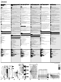
Installation
Installation
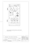
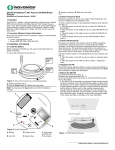
1. Use a screwdriver to open the housing (Fig. 1).
2. Pull the circuit board attachment latch and lift the circuit board out of the
housing (Fig. 2).
3. Wall tamper installation is required for BSI Class VI.
a. Use a 3/16” (4.8mm) bit to drill out the tamper rivet hole index.
b. Install the tamper wall anchor.
4. Mount the housing, using either the three wall-mount holes, or the four corner-mount holes (Fig 3).
a. Use a 5/32” (4 mm) bit to drill out the appropriate housing hole indexes.
b. Use the included screws to mount the housing.
5. If using the wall tamper, ensure the wall tamper rivet depresses the wall
tamper switch arm (Fig. 4).
6. If using the wall tamper, remove the wall tamper disable shunt (Fig 5).
7. Pull the tab from the battery’s + lead (Fig 6).
8. Use Fig 6 to select the jumper position appropriate for your geographic area.
9. Place a selection jumper on the appropriate frequency band selection pins
(Fig 5).
10. Press the Reset button (Fig 5).
11. If using the optional housing screws for added security, use a 7/64” (2.78
mm) bit to drill out the housing hole indexes on the top and bottom of the
housing.
12. Replace the housing cover.
13. If using the optional housing screws, use the included screws to secure the
housing.
1. Utilisez un tournevis pour ouvrir le boîtier (Fig. 1).
2. Tirez sur le loquet de fixation de la carte imprimée et soulevez la carte pour
la sortir du boîtier (Fig. 2).
3. L'installation murale du système anti-sabotage est obligatoire selon la norme
BSI Classe VI
a. Utilisez un foret de 4,8 mm pour percer le repère du trou du rivet antisabotage.
b. Installez la fixation murale anti-sabotage.
4. Montez le boîtier à l'aide des trois orifices muraux ou des quatre orifices de
fixation en coin (Fig. 3).
a. Utilisez un foret de 4 mm pour percer les repères appropriés des trous du
boîtier.
b. Utilisez les vis fournies pour fixer le boîtier.
5. Si vous utilisez l'anti-sabotage mural, vérifiez que le rivet anti-sabotage
mural appuie sur le bras du contacteur anti-sabotage mural (Fig. 4).
6. Si vous utilisez l'anti-sabotage mural, enlevez le conduit de désactivation de
l'anti-sabotage mural (Fig. 5).
7. Tirez la languette du fil + de la pile (Fig. 6).
8. Utilisez la Fig. 6 pour sélectionner la position correcte du cavalier pour votre
zone géographique.
9. Placez un cavalier sur les broches de sélection de la bande de fréquences
(Fig. 5).
10. Appuyez sur la touche de réinitialisation (Reset) (Fig. 5).
11. Si vous utilisez les quatre vis optionnelles du boîtier pour accroître la sécurité, utilisez un foret de 2,78 mm pour percer les repères des trous situés au
sommet et à la base du boîtier.
Testing
Once the battery is installed, the unit enters a three-minute non-alarming sta- 12. Replacez le couvercle du boîtier.
bilization period indicated by the LED flashing once per second. After the sta- 13. Si vous utilisez les vis optionnelles, utilisez les vis fournies pour fixer le
boîtier.
bilization period, the unit requires two seconds of quiet. After that two seconds, the unit will remain in walk test mode until it is left untripped for 120
Test
seconds.
1. During the three minute stabilization period, press and release the housing
Dès que la pile est installée, l'unité entre en période de stabilisation sans
tamper switch to cause a tamper transmission.
alarme pendant trois minutes, signalée par le clignotement de la DEL toutes les
2. When the stabilization period is complete, replace the housing and walk in
secondes. Après la période de stabilisation, une période de calme de deux secondes est nécessaire. Après cette période de deux secondes, l'unité reste en
front of the lens to create an alarm.
mode de test de fonctionnement jusqu'à ce qu'elle ne soit plus activée pendant
une période de 120 secondes.
Operation
1. Pendant la période de stabilisation de trois minutes, appuyez et relâchez le
Note: The LED is only used for testing. The LED will not light during normal
contacteur anti-sabotage du boîtier pour provoquer une transmission anti-sabooperation.
tage.
1. If masking is required, use the PIR zone diagram (Fig 7) and the lens inside 2. Quand la période de stabilisation est terminée, replacez le boîtier et marchez
view diagram (Fig 8) to choose the appropriate zones to be masked. Use opaque devant la lentille pour provoquer une alarme.
masking material, such as electrical tape.
2. To enable the look down zone, peel the mask from the look down lens (Fig
Fonctionnement
9).
Note : La DEL sert uniquement aux tests. La DEL ne s'allume pas pendant le fonctionnement normal.
A. Circuit board attachment latch
B. Tamper rivet hole index
1. Si un masquage est nécessaire, utilisez le schéma des zones du PIR (Fig. 7) et
C. Corner mount hole indexes
le schéma de vue interne de la lentille (Fig. 8) pour choisir le masquage des
D. Wall mount hole indexes
zones appropriées. Utilisez un matériau opaque comme du ruban isolant.
E. Tamper rivet
2. Pour activer la zone de détection vers le bas, décollez le masque de la lentille
F. Tamper switch arm
de détection vers le bas (Fig. 9).
G. Frequency selection pins
H. Wall tamper disable selection pins
A. Loquet de fixation de la carte imprimée
I. Battery
B. Repère de l'orifice du rivet anti-sabotage
J. Reset button
C. Repères des orifices de montage en coin
K. Housing tamper switch
D. Repères des orifices de fixation murale
E. Rivet anti-sabotage
F. Bras du contacteur anti-sabotage
G. Broches de sélection des fréquences
H. Broches de sélection de la désactivation de l'anti-sabotage mural
I. Pile
J. Bouton de réinitialisation
K. Contacteur anti-sabotage du boîtier
Sensore di movimento EchoStream® Select ES1262 PIR
Manuale di installazione e uso - 03844D
EchoStream® Select ES1262 Detector de movimiento PIR
Manual de instalación y funcionamiento - 03844D
Installazione
Instalación
EchoStream® Select ES1262 Passiv IR rörelsedetektor
Installations- och handhavandemanual - 03844D
EchoStream® ES-11262 PIR-ddetektor
Installations- og betjeningsmanual - 03844D
Installation
Installation
1. Con una cacciavite, aprire l'alloggiamento (Fig. 1).
1. Use un destornillador para abrir el alojamiento (Figura 1).
2. Tirare l'elemento di fissaggio della scheda circuitale e sollevare la scheda dal- 2. Tire del seguro de fijación de la placa de circuitos y levante la placa de cir-
1. Använd en flat skruvmejsel för att öppna kapslingen (Figur 1).
2. Skjut hållaren för kretskortet åt sidan och lyft ur kretskortet ur kapslingen
l'alloggiamento (Fig. 2).
3. L'installazione dell'interruttore anti-manomissione da parete è prevista per i
dispositivi di Classe VI BSI.
a. Con una punta da 3/16" (4.8 mm), trapanare il riferimento di foro del
rivetto anti-manomissione.
b. Montare l'ancoraggio antimanomissione.
4. Montare l'alloggiamento servendosi dei tre fori per montaggio a parete o dei
4 fori per montaggio all'angolo (Fig. 3).
a. Con una punta da 5/32" (4 mm), trapanare i riferimenti di fori sull'alloggiamento.
b. Utilizzare le viti incluse per montare l'alloggiamento.
5. Se si utilizza un interruttore anti-manomissione, accertarsi che il relativo rivetto premi il relativo braccio (Fig. 4).
6. Se si utilizza un interruttore anti-manomissione, rimuovere il relativo dispositivo di disattivazione (Fig. 5).
7. Tirare la linguetta del cavo positivo della batteria (Fig. 6).
8. Riferire alla Fig. 6 per selezionare la posizione del ponticello appropriata
all'area geografica di applicazione.
9. Posizionare un ponticello di selezione sui pin di selezione banda di frequenza
interessati (Fig. 5).
10. Premere il tasto Reset (Fig. 5).
11. Volendo fissare l'alloggiamento con viti opzionali per una maggiore sicurezza, con una punta da 7/64" (2.78 mm) trapanare i riferimenti di fori presenti
sulla parte superiore ed inferiore dell'alloggiamento.
12. Rimontare il coperchio dell'alloggiamento.
13. Se si utilizzano le viti opzionali, utilizzare le viti incluse per fissare l'alloggiamento.
(Figur 2).
3. Det krävs sabotageskydd för bortbrytning från vägg för installationer i BSI
Class VI.
a. Använd en 4,8 mm borr för att borra upp hålet markerat för sabotagekontakten.
b. Installera tryckankare för sabotagekontakten i väggen.
4. För montering, välj antingen de tre hålen för montering på plan yta eller de
fyra hålen för montering i hörn (Figur 3).
a. Använd en 4 mm borr för att borra upp skruvhålen för vald montering.
b. Använd sedan medföljande skruvar för att montera kapslingen.
5. Om sabotageskydd mot bortbrytning från vägg används, kontrollera att sabotagekontaktens arm trycks in av tryckankaret (Figur 4).
6. Om sabotageskydd mot bortbrytning från vägg används, tag bort bygeln som
bortkopplar ingången för denna sabotagekontakt (Figur 5).
7. Drag bort skyddet från batteriets +-ledare (Figur 6).
8. Se Figur 6 för att val av den radiofrekvens som skall gälla för detektorn.
9. Placera bygeln för vald radiofrekvens över rätt stift (Figur 5).
10. Tryck på återställningsknappen, Reset (Figur 5).
11. För att använda extra skruvar för bättre bortbrytningsskydd, använd då en
2.8 mm borr för att borra bort hålmarkeringarna upptill och nedtill i kapslingen.
12. Sätt tillbakakapslingens frontkåpa.
13. Om man så önskar, använd de extra kapslingsskruvarna för att skruva ihop
kapslingen.
1. Brug en skruetrækker til at åbne huset (Fig. 1).
2. Træk i printpladens låsepal, og løft printpladen ud af huset (Fig. 2).
3. Det er muligt at installere en sabotagekontakt mod væggen (til BSI Klasse VI
Verifica del funzionamento del trasmettitore
Una volta montata la batteria, l'unità entra in un periodo di stabilizzazione di
tre minuti, senza allarme, indicato dal LED che lampeggia una volta al secondo.
Al termine del periodo di stabilizzazione, l'unità ha bisogno di due secondi di
inattività. Al termine dei due secondi di inattività, l'unità rimane in modalità
test di movimento per 120, prima dell'attivazione.
1. Durante i tre minuti di stabilizzazione, premere e rilasciare l'interruttore antimanomissione per avviare una trasmissione e rilevare una manomissione spuria.
2. Al termine del periodo di stabilizzazione, montare l'alloggiamento e camminare davanti alla lenta per provocare un allarme.
Funzionamento
Nota: il LED è utilizzato solo per il test. Il LED non si accende durante il funzionamento normale.
1. Volendo mascherare, riferire allo schema zone PIR (Fig. 7) e allo schema vista
interna lente (Fig. 8) per scegliere le zone appropriate da mascherare. Utilizzare
materiale di mascheratura opaco (ad es. nastro per sistemi elettrici).
2. Per abilitare la zona look down, togliere la mascheratura dalla lente look
down (Fig. 9).
A. Elemento di fissaggio scheda circuitale
B. Riferimento di foro rivetto anti-manomissione
C. Riferimenti di fori montaggio all'angolo
D. Riferimenti di fori montaggio a parete
E. Rivetto anti-manomissione
F. Braccio interruttore antimanomissione
G. Pin selezione frequenza
H. Pin di selezione disattivazione interruttore antimanomissione a parete
I. Batteria
J. Tasto Reset
K. Interruttore anti-manomissione sull'alloggiamento
cuitos para sacarla del alojamiento (Figura 2).
3. Se necesita la instalación de seguridad anti-manipulación de pared para BSI
Clase VI.
a. Use una barrena de 3/16" (4,8 mm) para perforar el índice del orificio
para el remache anti-manipulación.
b. Instale el anclaje de pared anti-manipulación.
4. Monte el alojamiento, usando los tres orificios de montaje en la pared o los
cuatro orificios de montaje en el rincón (Figura 3).
a. Use una barrena de 5/32" (4 mm) para perforar el orificio de los índices
para los alojamientos apropiados.
b. Use los tornillos incluidos para montar el alojamiento.
5. Si usa el sistema anti-manipulación de pared, asegúrese de que el remache
anti-manipulación pulse el brazo del interruptor anti-manipulación de pared
(Figura 4).
6. Si usa el sistema anti-manipulación de pared, retire la derivación que desactiva el sistema anti-manipulación de pared (Figura 5).
7. Tire de la lengüeta desde el conductor + de la batería (Figura 6).
8. Utilice la figura 6 para seleccionar la posición del conector adecuada a su
área geográfica.
9. Sitúe un conector de selección en las clavijas de selección de banda de frecuencia apropiadas (Figura 5).
10. Pulse el botón de reposición (Figura 5).
11. Si usa los tornillos de alojamiento opcionales para mayor seguridad, utilice
una barrena de 7/64" (2,78 mm) para perforar los índices de los orificios del
alojamiento en las partes superior e inferior del alojamiento.
12. Vuelva a colocar la tapa del alojamiento.
13. Si usa los tornillos de alojamiento opcionales, utilice los tornillos incluidos
para fijar el alojamiento.
Test
När ett batteri satts på plats i enheten ställer sig denna först i ett treminuters
anpassningsläge, vilket indikeras genom att lysdioden blinkar en gång per
sekund. Efter denna anpassningstid behöver enheten två sekunders vila utan
någon påverkan. Efter dessa två sekunder kommer enheten att ställa sig i
Pruebas
gångtestläge till dess den lämnats opåverkad under 120 sekunder.
Una vez instalada la batería, la unidad entra en un período de estabilización de 1. Under den tre minuter långa anpassningstiden, tryck in och släpp sedan upp
tres minutos sin alarmas, indicado por el LED que parpadea una vez por segun- sabotagekontakten för att aktivera sändning av sabotagelarm.
2. När anpassningstiden löpt ut, sätt tillbaka frontkåpan och gå sedan framför
do. Luego del período de estabilización, la unidad necesita dos segundos de
silencio. Una vez transcurridos dos segundos, la unidad sigue en modo de prue- detektorns lins för att aktivera (lösa ut) larm.
ba de paseo hasta que no se activa durante 120 segundos.
1. Durante el período de estabilización de tres minutos, presione y suelte el
Funktion
interruptor anti-manipulación del alojamiento para provocar una transmisión de
Anm! Lysdioden används bara för test. Den kommer inte att lysa vid normal
manipulación indebida.
2. Una vez finalizado el período de estabilización, vuelva a colocar el alojamien- drift.
1. Om vissa zoner skall maskas bort, använd då figuren över avkänningszonernas
to y camine enfrente de la lente para generar una alarma.
placering (Figur 7) och figuren över zonernas läge på insidan av linsen (Figur 8)
för att välja rätt zoner som skall maskeras. Använd ett ogenomskinligt material
Funcionamiento
för bortmaskningen, t.ex. eltejp.
Nota: El LED se usa únicamente para las pruebas. El LED no se ilumina durante el 2. För att använda zonen för krypskydd, drag bort tejpen från linsen för krypskyfuncionamiento normal.
ddszonen (Figur 9).
1. Si se requiere un enmascaramiento, use el diagrama de zonas de PIR (Figura
A. Kretskortets hållare
7) y el diagrama de vista interior de la lente (Figura 8) para seleccionar las
zonas apropiadas a ser enmascaradas. Use material de enmascaramiento opaco, B. Hålmarkering för sabotageskydd mot vägg
C. Hålmarkeringar för hörnmontering
por ejemplo, cinta aislante.
2. Para activar la zona de observación inferior, quite la máscara de la lente de
D. Hålmarkeringar för montering på plan yta
E. Tryckankare
observación inferior (Figura 9).
F. Sabotagekontaktens arm
A. Seguro de fijación de la placa de circuitos
G. Stift för val av radioreekvens
B. Índice de los orificios de los remaches anti-manipulación
H. Stift för bygel för in-/bortkoppling av sabotageskydd mot bortbrytning från
C. Índices de los orificios de montaje en el rincón
vägg
D. Índices de los orificios de montaje en la pared
I. Batter
E. Remache anti-manipulación
J. Återställningsknapp (Reset)
F. Brazo del interruptor anti-manipulación
K. Sabotagekontakt för skydd mot öppning av enheten
G. Clavijas de selección de frecuencia
H. Clavijas de selección que desactivan el sistema anti-manipulación de pared
I. Batería
J. Botón de reposición
K. Interruptor del sistema anti-manipulación del alojamiento
- England).
a. Brug 5,0 mm bor til at bore udslagsblanketten for sabotageknappens
naglehul ud.
b. Montér sabotageknappens væganker.
4. Montér huset - enten ved hjælp af de tre vægmonteringshuller - eller de fire
hjørnemonteringshuller (Fig. 3).
a. Brug et 4,0 mm bor til at bore de relevante udslagsblanketter for husets
huller ud.
b. Benyt de medfølgende skruer til at montere huset.
5. Ved anvendelse af sabotagekontakt mod væggen kontrolleres det, at sabotagekontaktens nagle trykker dens arm ned (Fig. 4).
6. Ved anvendelse af sabotagekontakt mod væggen, fjernes den shunt som slår
den fra (Fig 5).
7. Træk tappen af batteriets +leder (Fig 6).
8. Brug Fig. 6 til at vælge den jumper-position, som passer til dit geografiske
område.
9. Placér en jumper på det ønskede frekvensbånds pins (Fig. 5).
10. Tryk på Reset-knappen (Fig. 5).
11. Hvis du benytter de ekstra skruer til huset, for at opnå større sikkerhed, så
brug et 3,0 mm bor, til at bore udslagsblanketterne for husets huller ud, på
toppen og bunden af huset.
12. Sæt huset på igen.
13. Hvis der anvendes ekstra skruer til huset, så benyt de medfølgende skruer til
at sikre det.
Afprøvning
Når batteriet er monteret, går enheden ind i tre minutters stabiliseringsperiode
uden alarmering, hvilket angives ved at lysdioden (LED) blinker én gang pr.
sekund. Efter stabiliseringsperioden har enheden brug for to sekunders stilstand. Efter disse to sekunder vil enheden forblive i gang-test mode, indtil den
efterlades upåvirket i 120 sekunder.
1. Under de tre minutters stabiliseringsperiode, skal du trykke på sabotageknappen på væggen, og slippe den igen, for at udløse en sabotagetransmission.
2. Når stabiliseringsperioden er afsluttet, sættes huset på igen, og gennemfør
en gang-test for at udløse en alarm.
Betjening
Bemærk: LED benyttes kun til afprøvning. LED´en lyser ikke under normal drift.
1. Hvis maskering er påkrævet, anvendes PIR-zonediagrammet (Fig. 7) - og diagrammet over linsens indadvendte segmenter (Fig. 8) - til at udvælge de zoner,
som skal maskeres. Brug et uigennemsigtigt materiale til maskering, som f.eks.
isoleringsbånd.
2. For at gøre brug af "look down"-zonen, trækkes masken af "look down"-linsen
(Fig. 9).
A.Printpladens fastgørelsespal
B. Udslagsblanket for sabotagekontaktens naglehul
C. Udslagsblanketter for hjørnemonteringshuller
D. Udslagsblanketter for vægmonteringshuller
E. Sabotagekontaktens nagle
F. Sabotagekontaktens arm
G. Pins til valg af frekvens
H. Pins til at slå sabotagekontakt mod væggen fra
I. Batteri
J. Reset-knap
K. Sabotagekontakt på huset (mod åbning)
Specifications
Spécifications
Dati tecnici
Especificaciones
Tekniska specifikationer
Specifikationer
Dimensions: 11.4 cm x 6.4 cm x 4.1 cm (4.5”H x 2.5”W x 1.6”D)
Operating temperature: 0° to 60°C (32° to 140°F)
Humidity: 0 - 90% (non-condensing)
Battery: 3V Lithium (CR123A or DL123A)
Typical battery life: Two years
Tamper: Housing and/or Wall (optional)
PIR: Detection Systems RF940U
PIR RF interference immunity: Greater than 30 v/m 26 MHz - 1 GHz
Detection zone: 12.2m x 12.2 m (40’ x 40’) with lookdown zone
Alarm Lockout Time: Three minutes
Mounting height: 2.1 to 2.7 m (7 to 9 feet)
Dimensions : 11,4 cm x 6,4 cm x 4,1 cm
Température d'utilisation : 0° à 60°C
Humidité : 0 - 90% (sans condensation)
Pile : 3V lithium (CR123A ou DL123A)
Vie utile de la pile : Deux ans
Système anti-ssabotage : Boîtier et/ou mural (en option)
PIR : Systèmes de détection RF940U
Immunité du PIR aux perturbations radioélectriques : Plus de 30 v/m 26 MHz - 1 GHz
Zone de détection : 12,2 m x 12,2 m avec zone de détection vers le bas
Délai de déclenchement de l'alarme : Trois minutes
Hauteur de montage : 2,1 à 2,7 m
Dimensioni: 11.4 (altezza) x 6.4 (larghezza) x 4,1 (profondità) cm (4.5 x 2.5 x
1.6")
Temperatura di esercizio: da 0° a 60°C (da 32° a 60,00°C)
Umidità: 0 - 90% (senza condensa)
Batteria: al litio da 3V (CR123A o DL123A)
Durata tipica della batteria: 2 anni
Interruttore anti-m
manomissione: sull'alloggiamento e/o da parete (opzionale)
PIR: Sensori di rilevamento: RF940U
PIR Immunità alle interferenze RF: superiore a 30 v/m 26 MHz - 1 GHz
Zona di rilevamento: 12.2 x 12.2 m (40" x 40") con zona look down
Tempo disattivazione allarme: 3 minuti
Altezza di montaggio: da 7 a 9 piedi (da 2.1 a 2.7 m)
Dimensiones: 11,4 cm x 6,4 cm x 4,1 cm (4,5" altura x 2,5" ancho x 1,6" profundidad)
Temperatura de funcionamiento: 0° a 60° C (32° a 140° F)
Humedad: 0 - 90% (sin condensación)
Batería: 3,0 V de litio (CR123A o DL123A)
Vida típica de la batería: Dos años
Seguridad anti-m
manipulación: De alojamiento y/o pared (opcional)
PIR: Sistemas de detección RF940U
Inmunidad contra interferencias de RF en la unidad PIR: Superior a 30 v/m 26 MHz - 1 GHz
Zona de detección: 12,2m x 12,2 m (40' x 40') con zona de observación inferior
Tiempo de bloqueo de alarma: Tres minutos
Altura de montaje: 2,1 a 2,7 m (7 a 9 pies)
Mått (H x B x D): 11,4 x 6,4 x 4,1 cm
Temperaturopmråde i drift: 0° - 60° C
Luftfuktighet: 0 - 90 % (icke kondenserande)
Batteri: 3V litium (CR123A eller DL123A)
Batteriets normala livslängd: Två år
Sabotageskydd: Mot öppning och/eller bortbrytning från underlaget
Passiv IR: Detection Systems RF940U
Immunitet mot radiostörningar: Bättre än 30 V/m för 26 MHz - 1 GHz
Bevakningsområde: 12,2 x 12,2 m med krypskyddzon
Blockeringstid (utan rörelse) efter utlöst larm: Tre minuter
Monteringshöjd: 2,1 - 2,7 m
Dimensioner:
(tillval)
11,4 cm x 6,4 cm x 4,1 cm (4.5"H x 2.5"B x 1.6"D)
Dimensioner: (h x b x d): 11,4 cm x 6,4 cm x 4,1 cm
Driftstemperatur: 0° til 60°C
Fugtighed: 0 - 90% R.F. - ikke kondenserende
Batteri: 3V Lithium (CR123A eller DL123A)
Typisk levetid for batteri: 2 år
Sabotagekontakt: Mod åbning og/eller mod nedrivning (ekstraudstyr)
PIR: Detektionssystem RF940U
HF-iimmunitet: Større end 30 V/m, fra 26 MHz til 1 GHz
Detektions-zzone: 12,2 m x 12,2 m, "lookdown"-zone
Alarmens lockout-ttid: 3 minutter
Monteringshøjde: 2,1 til 2,7 m
email: [email protected] i www.inovonicswireless.com
© 2005 Inovonics Wireless Corporation
G
H
B
D
C
NZ (921-9928 MHz)
I
C
D
EU (868-8869 MHz)
E
F
A
J
AU (915-9928 MHz)
K
D
C
Fig 1
Fig 2
Fig 3
NA (902-9928 MHz)
C
Fig 4
Fig 5
Fig 6
Fig 7
Fig 8
Fig 9