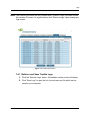
1
EN6080 Area Control Gateway User Manual Table of Contents Preface 4 Chapter 1 EN6080 Area Control Gateway Overview 6 1.1 Introduction ..................................................................................................... 6 1.2 Recommended System Requirements ......................................................... 7 1.3 EN6080 Area Control Gateway Initial Setup and Connection .................... 7 1.3.1 Disable Delayed ACK Mode on the Windows® 7 Operating System .............7 1.3.2 Configure Network Settings (for Windows 7) ...................................................9 1.3.3 Browse to the EN6080 Area Control Gateway Web Server Screens ..............10 1.3.4 License Key Setup ..............................................................................................10 Chapter 2 Home 12 2.1 Home ................................................................................................................ 12 2.1.1 System Connection Summary ...........................................................................13 2.1.2 Device Information ..............................................................................................13 2.2 Site Information .............................................................................................. 14 2.2.1 ACG Information .................................................................................................15 2.2.2 Contact Information ............................................................................................15 Chapter 3 ACG Setup 16 3.1 User Administration ....................................................................................... 16 3.1.1 Update User or Admin Password ......................................................................17 3.2 IP Administration ............................................................................................ 17 3.2.1 Configure a Static IP Address ...........................................................................18 3.2.2 Configure a DHCP IP Address ...........................................................................18 3.3 Date and Time Setup ...................................................................................... 19 3.3.1 Poll NTP Servers for Time and Date ..................................................................20 3.18.15 06443E © 2015, Inovonics - www.inovonics.com 1 Table of Contents 3.3.2 Synchronize Time and Date with your PC ........................................................21 Chapter 4 Partitions 22 4.1 Partitions ......................................................................................................... 22 4.2 Define a New Partition .................................................................................... 24 4.3 Assign Devices to a Partition ........................................................................ 24 4.4 Remove Devices from a Partition ................................................................. 24 4.5 Update a Partition ........................................................................................... 25 4.6 Delete a Partition ............................................................................................ 25 Chapter 5 Wireless Setup 26 5.1 Wireless Setup ................................................................................................ 26 5.1.1 Update the NID ....................................................................................................27 Chapter 6 Device Setup 29 6.1 Manual Administration ................................................................................... 30 6.1.1 Manually Register a Device ................................................................................31 6.1.2 Unregister a Registered Device .........................................................................32 6.2 Automatic Administration .............................................................................. 32 6.2.1 Start Discovery ....................................................................................................33 6.2.2 Edit and Register the Devices ...........................................................................33 6.2.3 Unregister a Registered Device .........................................................................34 6.3 Upload Administration ................................................................................... 34 6.3.1 Upload a Spreadsheet of Devices to Register ..................................................36 Chapter 7 Logs 38 7.1 Logs ................................................................................................................. 38 7.2 Alarm Logs ...................................................................................................... 39 7.2.1 Retrieve and Save Logs .....................................................................................40 7.3 System Logs ................................................................................................... 40 7.3.1 Retrieve and Save System Logs ........................................................................41 7.4 Trouble Logs ................................................................................................... 41 7.4.1 Retrieve and Save Trouble Logs .......................................................................42 3.18.15 06443E © 2015, Inovonics - www.inovonics.com 2 Table of Contents Chapter 8 File Management 43 8.1 System and Configuration Files .................................................................... 43 8.1.1 Back Up Configuration Files ..............................................................................44 8.1.2 Restore Configuration Files ...............................................................................44 8.2 Firmware Update ............................................................................................ 45 8.2.1 Update Firmware .................................................................................................46 Glossary 3.18.15 06443E © 2015, Inovonics - www.inovonics.com 47 3 Preface Notice © 2015, Inovonics Inovonics intends this manual for use by Inovonics customers only. All comments concerning the contents of this manual should be directed to the Inovonics marketing department. No part of this work covered by copyright may be reproduced in any form either graphically, electronically or mechanically; including photocopying, recording, taping or storing in an information retrieval system without prior written permission from Inovonics. Document Part Number 06443E Trademarks Windows is a registered trademark of Microsoft Corporation in the United States and other countries. Mozilla and Firefox are registered trademarks of the Mozilla Foundation. Celeron, Core, Pentium, and Intel are trademarks of Intel Corporation in the U.S. and/or other countries. All brand other names and product names used in this manual are trademarks, registered trademarks or trade names of their respective holders. 3.18.15 06443E © 2015, Inovonics - www.inovonics.com 4 Preface Technical Services Contact Information For Inovonics technical services: • E-mail: [email protected] • Phone: (800) 782-2709; (303) 939-9336 Document Conventions The following notices are used throughout this document: Note: Emphasizes points, provides supplementary information or indicates minor problems in an expected outcome. Caution: Indicates possible damage to equipment or loss of data, as well as potential problems in an expected outcome. Warning: Indicates the possibility of minor injury to oneself or others. Danger: Indicates the possibility of serious or fatal injury to oneself or others. 3.18.15 06443E © 2015, Inovonics - www.inovonics.com 5 Chapter 1 EN6080 Area Control Gateway Overview 1.1 Introduction The Inovonics EN6080 area control gateway bridges the Inovonics proprietary commercial mesh network to a standard TCP/IP over Ethernet LAN, allowing the entire range of Inovonics physical security products to be added to any IPbased or PSIA revision 0.8 compliant system using RESTful web services. Inovonics security products include motion detectors, glassbreak sensors, panic buttons and door/window sensors. All of these operate on the selfmonitored and fully-supervised Inovonics EchoStream commercial mesh network. Designed to move small amounts of data over a moderate range in commercial environments, the commercial mesh network uses a frequencyhopping, spread-spectrum technology that sends redundant messages across multiple channels to avoid interference obstacles. Due to its low latency and high reliability, the EchoStream commercial mesh network is an ideal solution for security applications. The network is secure and dedicated, ensuring personal security messages are delivered without interference from less critical applications. The EN6080 area control gateway includes a built-in web page server for complete system setup and configuration, as well as enhanced, on-demand system supervision for detailed event audits. This manual covers the EN6080 area control gateway’s web page server. For installation information, see the EN6080 Area Control Gateway Installation Instructions; for information about integrating the EN6080 area control gateway into a PSIA revision 0.8 system, see the EN6080 Area Control Gateway Integration Guide. 3.18.15 06443E © 2015, Inovonics - www.inovonics.com 6 EN6080 Area Control Gateway Overview 1.2 Recommended System Requirements The computer used to access the EN6080 area control gateway should meet the following requirements: • Windows® 7 operating system or later. • Mozilla® Firefox® version 35 or later; Internet Explorer® version 11 or later. • Wired Ethernet interface. • Minimum MTU 1280 bytes 1.3 EN6080 Area Control Gateway Initial Setup and Connection 1.3.1 Disable Delayed ACK Mode on the Windows® 7 Operating System The EN6080 area control gateway currently does not respond to the delayed ACK mode of operation that some Windows 7 machines use. Microsoft has provided a fix for this as outlined below. A future revision of the EN6080 software will eliminate the need for this fix. To disable delayed ACK mode in Windows 7 Service Pack 1 or above: 3.18.15 06443E © 2015, Inovonics - www.inovonics.com 7 EN6080 Area Control Gateway Overview 1. Open up the registry. Figure 1-1 Open the registry 2. Un-collapse the following entry: [HKEY_LOCAL_MACHINE\SYSTEM\CurrentControlSet\services\Tcpip\P arameters\Interfaces] 3. You will probably find several subfolders. Click through each folder until you find the one with the most entries in the right pane. The correct interface will have many entries. For example: DGCPDefaultGateway, DHCPDomain, DHCPIPAddress, Lease, NameServer, T1, etc. Figure 1-2 Find the subfolder with the most entries 3.18.15 06443E © 2015, Inovonics - www.inovonics.com 8 EN6080 Area Control Gateway Overview 4. For each of those entries in the Interfaces folder, create two DWORD registry keys called TCPAckFrequency and TCPNoDelay. Figure 1-3 Create DWORD registry keys Here’s an example what it should look like: Figure 1-4 Edited entry example 5. Double-click on each new registry key and change the value from 0 to 1. (Base hexadecimal.) 6. Exit the registry editor. 7. Reboot your PC. 1.3.2 Configure Network Settings (for Windows 7) The EN6080 area control gateway comes from the factory configured with a static IP address of 192.168.60.80. To initially communicate with the EN6080 area control gateway, you will need to connect to a computer's Ethernet port. This might mean disconnecting from your LAN. To connect to the EN6080 area control gateway, you will first need to configure the network settings on your computer. Note: This procedure will change your network settings. Make a note of your current network configuration, so you can return to it when finished interfacing with the EN6080 area control gateway. 1. From the control panel, click “Network and Internet.” 2. Click “Network and Sharing Center.” 3. Click “Change adapter settings.” 4. Right click on the local area connection used to connect to the network, and select “Properties.” 3.18.15 06443E © 2015, Inovonics - www.inovonics.com 9 EN6080 Area Control Gateway Overview 5. Double click “Internet Protocol Version 4 (TCP/IPv4).” 6. Select the “Use the following IP address” radio button. 7. Set the IP address to 192.168.60.1. 8. Set the subnet mask to 255.255.255.0. 9. Click “OK.” 1.3.3 Browse to the EN6080 Area Control Gateway Web Server Screens 10. Open the Mozilla Firefox or Internet Explorer web browser and enter “http://192.168.60.80” in the address field. 11. When prompted, enter the admin username and password. 12. Click the “OK” button. Note: For more information about placing the EN6080 area control gateway on your local network see 3.2, “IP Administration” on page 17. 1.3.4 License Key Setup You should have received a license key to enable your EN6080 area control gateway from the Inovonics customer service department. To enter the license key: 1. Click the “File Management” tab. 2. Click “License Key” to display the license key page. 3.18.15 06443E © 2015, Inovonics - www.inovonics.com 10 EN6080 Area Control Gateway Overview Figure 1-5 The license key screen 3. Enter the license key received from Inovonics in the “Enter License Key:” field. 4. Click the “Update” button. 5. Once the “License Update” message has displayed and the EN6080 area control gateway has rebooted, click the “Refresh” button. 6. Your EN6080 is now enabled to support the number of end devices allowed within the purchased tier. 3.18.15 06443E © 2015, Inovonics - www.inovonics.com 11 Chapter 2 Home 2.1 Home The home screen displays a overview of system information, and allows access to the site information screen. Figure 2-1 EN6080 area control gateway home screen 3/18/15 06443E © 2015, Inovonics - www.inovonics.com 12 Home 2.1.1 System Connection Summary The system connection summary fields on the home screen allow the system to be viewed at a glance. • The “Devices Registered” field displays the total number of devices registered to the EN6080 area control gateway. • The “Devices In Alarm” field displays the number of registered devices that are in alarm. • The “Devices Inactive” field displays the number of registered devices that are inactive. A device is considered inactive if the EN6080 area control gateway has not received a check-in message from the device during the supervision window, indicating the radio link has been broken. 2.1.2 Device Information The device information table (located below the system connection summary) displays an overview of each registered device. All columns are sortable; simply click on any column header to sort in ascending or descending order. The search field can be used to locate specific devices; it covers data in all fields, and accepts letters and numbers, but no wildcard characters. The following information is included: • The “TX ID” field displays the factory coded unique identification number of the transmitter. The TX ID is primarily used for registration. • The “Device Status” field displays whether the device is active or inactive. A device is considered active if a check in message has been received during the programmed supervision period, indicating the radio link is sound. • The “Alarm State” field displays whether or not the device is in a state of alarm. • The “Type” field displays the Inovonics model number and device type. • The “Description” field displays the user defined description of the device. Typically, this is a brief indication of where the end device is used, or, in the case of a mobile device, the name of the person to whom it is assigned. • The “Partition” field displays the user defined area to which devices are assigned as a single entity. For instance, “front door,” or “lobby.” Placing 3/18/15 06443E © 2015, Inovonics - www.inovonics.com 13 Home the cursor over any number in the partitions column will display the name of the partition, as shown in Figure 2-2. Figure 2-2 Partition name 2.2 Site Information The site information screen is used to view EN6080 area control gateway information and edit site information. It is only accessible to admin level users. Figure 2-3 The EN6080 area control gateway site information screen 3/18/15 06443E © 2015, Inovonics - www.inovonics.com 14 Home 2.2.1 ACG Information Displays information about the EN6080 area control gateway. • The “EN6080 Serial Number:” field displays the factory coded unique serial number of the EN6080 area control gateway. • The “Manufacture Date:” field displays the manufacture date of the EN6080 area control gateway. • The “Firmware Version:” field displays the version of the firmware loaded in the EN6080 area control gateway. 2.2.2 Contact Information Though optional, contact information should be provided to allow a remote administrator to contact the local technician in the event of maintenance or updates. To fill out contact information: 1. Enter the name of the facility in which the EN6080 area control gateway is being used in the “Facility Name” field. Up to 30 characters can be entered. 2. Enter the first name of the contact for the facility in the “First Name” field. Up to 100 characters can be entered. 3. Enter the last name of the contact for the facility in the “Last Name” field. Up to 100 characters can be entered. 4. Enter the phone number for the contact for this facility in the “Phone 1” field. The two phone number formates accepted are: XXX XXX-XXXX and XXXXXXXXXX. 5. Optionally, enter a second phone number for in the “Phone 2” field. The two phone number formates accepted are: XXX XXX-XXXX and XXXXXXXXXX. 6. Click “Update” to submit the site information to the EN6080 area control gateway for storage. 3/18/15 06443E © 2015, Inovonics - www.inovonics.com 15 Chapter 3 ACG Setup 3.1 User Administration When the ACG setup tab is clicked, the user administration screen displays. The user administration screen is used to edit user and admin passwords, and provides access to the IP administration and date and time setup screens. It is only accessible to admin level users. Figure 3-1 EN6080 area control gateway user administration screen 3/18/15 06443E © 2015, Inovonics - www.inovonics.com 16 ACG Setup 3.1.1 Update User or Admin Password To change the user or admin password: 1. Enter the new password in the “Password” field under “Username: Admin” or “Username: User.” Passwords must be 15 characters or less, and can include alpha-numeric characters only. 2. Reenter the new password in the “Reenter Password” field. 3. Click “Update” to change the password. Note: An admin password change will take effect immediately, and you will be asked to re-enter it to leave the page. 3.2 IP Administration The IP administration screen is used to configure the IP address of the EN6080 area control gateway. It is only accessible to admin level users. Figure 3-2 EN6080 area control gateway IP setup screen 3/18/15 06443E © 2015, Inovonics - www.inovonics.com 17 ACG Setup 3.2.1 Configure a Static IP Address By default, the EN6080 is configured with a static IP of 192.168.60.80 and a subnet mask of 255.255.255.0. Before configuring the IP address, you will need to attain a known good static IP address, subnet mask, and gateway on the target network from your IP administrator. To configure a static IP address: 1. Select “Static” to choose a static IP address for the EN6080 area control gateway. 2. Enter the known good IP address in the “IP:” field. 3. Enter the subnet mask of the IP network in the “Subnet:” field. 4. Enter the gateway for this IP network in the “Gateway:” field. 5. Click “Update” to configure the EN6080 area control gateway IP address. 6. A dialog box will display, reading “This update will require a reboot of the ACG. Once you make this change the browser will automatically update to the new address. Are you sure you want to make this change?” Click “OK.” 7. When the “Refresh” button displays, click it. 3.2.2 Configure a DHCP IP Address By default, the EN6080 is configured with a static IP of 192.168.60.80 and a subnet mask of 255.255.255.0. You will also need to ensure that the target network has a DHCP server on it. 1. Select the “DHCP” radio button. 2. Click “Update.” 3. A dialog box will display, reading “This update will require a reboot of the ACG. Once you make this change the browser will automatically update to the new address. Are you sure you want to make this change?” Click “OK.” 3/18/15 06443E © 2015, Inovonics - www.inovonics.com 18 ACG Setup The EN6080 area control gateway will request a new IP address from the DHCP server and, if successful, display the IP update dialog box shown in Figure 3-3. Write down the new IP address displayed in the IP update dialog box. Figure 3-3 IP update dialog box 4. Click “Accept New IP.” 5. The EN6080 area control gateway will reboot. When the “Refresh” button displays, click it. 3.3 Date and Time Setup The EN6080 area control gateway contains a real time clock that is used to tag events and log entries. The date and time setup screen is used to configure the date and time of that clock. It is only accessible to admin level users. The area control gateway can either poll the Network Time Protocol servers to automatically synchronize the time and date, or synchronize time and date with the computer connected to the EN6080. If the time reported by the EN6080 area control gateway differs from the time setting on the computer by more than five seconds, it will be reported on the home page. Discrepancies as small as one second will be reported on the date and time setup page. 3/18/15 06443E © 2015, Inovonics - www.inovonics.com 19 ACG Setup Figure 3-4 EN6080 area control date and time setup screen 3.3.1 Poll NTP Servers for Time and Date This requires that the EN6080 area control gateway be on a network that allows access to NTP servers. To automatically synchronize time and date with Network Time Protocol servers: 1. Click “Use NTP: (IP).” 2. A default NTP server address displays. If you do not want to use the default IP address, enter any known NTP server IP address. 3. Click “Update.” 4. When the “Date and Time configuration updated” dialog box displays, click “OK.” If the new time setting differs from the time on your computer by more than one second, it will be noted on the date and time setup page. 3/18/15 06443E © 2015, Inovonics - www.inovonics.com 20 ACG Setup If the IP address for the NTP server is invalid or the area control gateway is unable to connect, a message will display reading, “NTP Time Server is unreachable,” and the area control gateway will continue trying again to retrieve the time once a minute until it is successful. 3.3.2 Synchronize Time and Date with your PC To synchronize time and date with your computer: 1. Ensure the time and date is correct on your host computer. 2. Click the “Sync with PC:” button. 3. Click “Update” to update time and date. 4. When the “Date and Time configuration updated” dialog box displays, click “OK.” Note: If the new time and date is earlier than what is currently set on the EN6080 area control gateway, every event that happens after you set the new time will have a time stamp of 1 millisecond greater than the last entry before the time change. This will continue until the current time is greater than what the modified event time would be. At that point events will display the proper time stamp. This prevents log irregularities. 3/18/15 06443E © 2015, Inovonics - www.inovonics.com 21 Chapter 4 Partitions 4.1 Partitions The partitions tab is used to add, delete and manage partitions. Partitions are user defined controllable areas to which devices are assigned and managed as a single entity. For instance, “lobby” might be a partition, with all the devices that provide security to the lobby assigned to it so they can be managed together. The EN6080 area control gateway can manage up to 500 individual partitions. It is only accessible to admin level users. All columns in the registered devices and partitions fields are sortable; simply click on any column header to sort in ascending or descending order. The search fields can be used to locate specific devices or partitions; they cover data in all fields, and accept letters and numbers, but no wildcard characters. 3/18/15 06443E © 2015, Inovonics - www.inovonics.com 22 Partitions Figure 4-1 Partitions screen Once a partition is defined, the assigned number will display on the home page in the partitions field. Placing the cursor over any number in the partitions column will display the name of the partition, as shown in Figure 4-2. Figure 4-2 Partition name 3/18/15 06443E © 2015, Inovonics - www.inovonics.com 23 Partitions 4.2 Define a New Partition To define a new partition: 1. Click “Define New.” 2. Enter a descriptive name for the partition in the pop-up text field. The name can be up to 63 characters. 3. Click “Create.” The first partition will be created starting with an ID of “1.” Additional partitions will be created with sequentially increasing IDs. 4.3 Assign Devices to a Partition The create and assign partition field displays all devices in the system and allows them to be added and removed from partitions. Each device can be assigned to up to four partitions, so they can be managed separately. For instance, a door contact transmitter mounted on the door to a pharmacy in a supermarket might be assigned to both a “pharmacy” and a “building” partition. That way one could manage the pharmacy separately from the rest of the building, or manage the entire building as a whole. To assign devices to a partition: 1. Click the checkbox next to all devices you wish to assign to the partition. 2. Select the partition to which you wish to assign the devices. 3. Click the “Assign to Partition” button. 4.4 Remove Devices from a Partition To remove devices from a partition: 1. Click the checkbox next to all devices you wish to remove from a partition. 2. Select the partition from which you wish to remove the end devices. 3. Click the “Remove from Partition” button. 3/18/15 06443E © 2015, Inovonics - www.inovonics.com 24 Partitions 4.5 Update a Partition The name of an assigned partition may be edited. To edit an existing partition: 1. Click the partition you wish to update. 2. Click “Edit.” 3. Edit the name of partition in the pop-up text field. 4. Click “Update.” Once edited, the ID number assigned when the partition was created will remain the same. 4.6 Delete a Partition All devices must be removed from a partition before it can be deleted. To delete a partition: 1. Click the partition you wish to delete. 2. Click “Delete.” 3. Click “OK” to confirm deletion. 3/18/15 06443E © 2015, Inovonics - www.inovonics.com 25 Chapter 5 Wireless Setup 5.1 Wireless Setup The wireless setup tab is used to set up the network id (NID) of the EchoStream network. The NID is used by the network of high-power repeaters and two-way end devices to keep messages in separate EchoStream networks from overlapping. It is only accessible to admin level users. Figure 5-1 Wireless setup screen 3/18/15 06443E © 2015, Inovonics - www.inovonics.com 26 Wireless Setup 5.1.1 Update the NID To update the NID. 1. Select a NID from the “Network ID (NID)” dropdown menu. Make sure the NID you select is different from that of any other EchoStream systems that might interfere with yours. Caution: The NID setting of 0 is only used for diagnostics purposes. Make sure the NID you pick is greater than 0. 2. Click “Update” to change to the new NID. 3. The following displays. Click “Update” to continue. Figure 5-2 Repeater reset warning message 4. A list of repeaters registered to the system will display in a pop-up window. Figure 5-3 Registered repeaters 5. Go to the first repeater in your system. 3/18/15 06443E © 2015, Inovonics - www.inovonics.com 27 Wireless Setup 6. Open the cover and press the reset button. 7. Wait ten seconds and replace the cover. 8. Make sure a check displays next to the repeater you just reset in the window shown in Figure 5-3. If not, reset the repeater again, making sure to wait ten seconds before replacing the cover; if so, reset the next repeater. Repeat until all repeaters in the system have been reset. 9. Once all repeaters are reset, Click “Close” on the reset checkbox window. All repeaters are now registered. 10. Navigate to the home screen and ensure all repeaters are shown as active within three to four minutes. 3/18/15 06443E © 2015, Inovonics - www.inovonics.com 28 Chapter 6 Device Setup The device setup tab is used to register, unregister and manage the Inovonics devices and repeaters that make up your system. It is only accessible to admin level users. There are three ways to register the Inovonics end devices and repeaters that make up your security system: • Manually, by inputting device information • Automatically, with a reset button push • By uploading a .csv file with all registration information already inputted Up to 3000 Inovonics end devices and 500 repeaters can be added to a single EN6080 area control gateway, depending on the type of license purchased. 3/18/15 06443E © 2015, Inovonics - www.inovonics.com 29 Device Setup 6.1 Manual Administration The manual administration screen is used to register, unregister and manage devices and repeaters by directly inputting transmitter information. All columns are sortable; simply click on any column header to sort in ascending or descending order. The search field can be used to locate specific devices; it covers data in all fields, and accepts letters and numbers, but no wildcard characters. Figure 6-1 Manual administration screen 3/18/15 06443E © 2015, Inovonics - www.inovonics.com 30 Device Setup 6.1.1 Manually Register a Device 1. Enter the transmitter number of the Inovonics device to be registered in the “TX ID” field. The TX ID label is usually found on the printed circuit board of the device, or in the case of some devices, such as panic buttons, on the external housing. TX ID label Figure 6-2 TX ID label on a printed circuit board Note: The TX ID consists of the initial two smaller digits and the following six larger digits. Enter all digits. In the example shown in Figure 6-2, for instance, you would enter “07155450”. 2. Enter a 31 character or less text description of the device in the “Description:” field. Typically, this is a brief indication of where the device is used, or, in the case of a mobile device, the name of the person to whom it is assigned. 3. Choose the Inovonics part number of the device from the “Type:” dropdown menu. Note: If the exact product match is not available, choose the closest part number. E.g., “EN5040” may be selected for “EN5040-20T.” 4. In the “Supervision Window:” field, enter a supervision window for the device in seconds. Note: The supervision window is the period of time during which the EN6080 must hear a check-in message from the device or consider it inactive. For instance, if a device is set with a supervision window of 540 seconds and 540 seconds elapses without the EN6080 hearing a check-in message, then the device will be considered inactive. A good rule of thumb is to set the supervision window at a minimum of ten times the device’s check-in rate. 3/18/15 06443E © 2015, Inovonics - www.inovonics.com 31 Device Setup 5. Click “Register” to complete registration of the device. 6.1.2 Unregister a Registered Device To unregister a registered device: 1. Click the checkbox next to the registered device you wish to unregister. 2. Click “Unregister.” 3. Click “OK” to confirm. 6.2 Automatic Administration The automatic administration screen is used to discover Inovonics end devices and repeaters by the push of a reset button. Once the EN6080 area control gateway is set into discovery mode, a push of a transmitter’s reset button will automatically populate the transmitter’s identification number and product type. All columns are sortable; simply click on any column header to sort in ascending or descending order. The search field can be used to locate specific devices; it covers data in all fields, and accepts letters and numbers, but no wildcard characters. Figure 6-3 Automatic administration screen 3/18/15 06443E © 2015, Inovonics - www.inovonics.com 32 Device Setup 6.2.1 Start Discovery To discover devices by automatic administration: 1. Click “Start Discovery” to start discovery mode. During discovery mode, all unregistered end devices from which a reset message is heard will populate in the discovered devices field. 2. Press the reset button on all devices which you wish to register. Note: For specific information about the location of device’s reset button, refer to the installation instructions for the device you are registering. All installation instructions are available at www.inovonics.com. 3. When you have discovered all the devices to be registered, click the “Stop Discovery” button. 6.2.2 Edit and Register the Devices Once devices are discovered, they must be registered to include a description and supervision window. 4. All of the devices discovered in the last session will be highlighted in green, indicating they are ready to be registered. If you do not wish to register a device at this point, click anywhere in the device’s field to deselect it. 5. Click the “Edit” button. 6. Enter a text description (32 character or less) of the end device in the “Description:” field. Typically, this is a brief indication of where the end device is used, or, in the case of a mobile device such as a panic button, the name of the person to whom it is assigned. 7. In the “Supervision Window:” field, enter a supervision window for the end device in seconds. 3/18/15 06443E © 2015, Inovonics - www.inovonics.com 33 Device Setup Note: The supervision window is the period of time during which the EN6080 must hear a check-in message from the end device or consider it inactive. For instance, if a device is set with a supervision window of 540 seconds and 540 seconds elapses without the EN6080 hearing a check-in message, then the device will be considered inactive. A good rule of thumb is to set the supervision window at a minimum of ten times the device’s check-in rate. Most Inovonics security products have a check-in time of three minutes, or 180 seconds. Note: When you enter the supervision time for the first listed device, it will automatically populate the supervision field for all other listed devices. If this is desirable, no further input for supervision time is needed. If not, you can overwrite devices with different supervision times. 8. When you have edited all devices, click “Register.” 6.2.3 Unregister a Registered Device To unregister a registered device: 1. Click the checkbox next to the registered device you wish to unregister. 2. Click “Unregister.” 3. Click “OK” to confirm. 6.3 Upload Administration The upload administration screen is used to register Inovonics end devices and repeaters by uploading a spreadsheet with the transmitter information already entered. The file needs to be a comma delimited text file, and each device to be registered needs to be a separate line in the following format: TX ID, Type, Description, Supervision Window, Reserved1, Reserved2, Reserved3 • TX ID is the unique serial number for each Inovonics end device. The serial number can usually be found on the printed circuit board of the end device. 3/18/15 06443E © 2015, Inovonics - www.inovonics.com 34 Device Setup • Type represents the Inovonics model number of the end device, including: EN1210, EN1210-240, EN1210-60, EN1210EOL, EN1210W, EN1210W-60, EN1212, EN1212-60, EN1215, EN1215EOL, EN1215W, EN1215WEOL, EN1216, EN1223D EN1223D-15, EN1223S, EN1223S-15, EN1223S-60, EN1224, EN1224-ON, EN1233D, EN1233S, EN1235D, EN1235DF, EN1235S, EN1235SF, EN1235SF-15, EN1236D, EN1238D, EN1240, EN1241-60, EN1242, EN1247, EN1249, EN1252, EN1260, EN1261HT, EN1262, EN1265, EN1941, EN1941-60 • Description is a 32 or less character string describing the device. Typically, this is a brief indication of where the end device is used, or, in the case of a mobile device such as a panic button, the name of the person to whom it is assigned. • Supervision is a decimal number between 1 and 999999999, up to nine digits, representing the seconds to wait until a device is declared inactive. The EN6080 area control gateway trims the extra spaces on the start and end, and they are case-insensitive. TX ID, Type, and Supervision are required fields. All other fields may be empty, but must have a comma. Following is an example of a correctly formatted .csv file: • 1050958,EN1249,all team,7200,,, • 1009716,EN1223S,joes office,7200,,, • 1289716,EN1242,hallway,7200,,, • 1059246,EN1215W,lab area,7200,,, • 1664246,EN1240,board room,7200,,, 3/18/15 06443E © 2015, Inovonics - www.inovonics.com 35 Device Setup Figure 6-4 Upload administration screen 6.3.1 Upload a Spreadsheet of Devices to Register 1. Click “Browse.” 2. Navigate to the .csv file of devices you wish to register. 3. Click “Open.” 4. Click the “Load” button. 5. All devices that parse properly and are unregistered will be selected by default. Deselect any devices that you do not want to register. 6. Click “Register”. Note: You can also unregister devices by highlighting the devices you want to unregister and clicking “Unregister.” 3/18/15 06443E © 2015, Inovonics - www.inovonics.com 36 Device Setup If there are lines that cannot be parsed due to formatting errors a red warning with the number of unparsed lines will display in the bottom left portion of the screen as shown in Figure 6-5. Hold the cursor over the warning message for details. Figure 6-5 Formatting errors message 3/18/15 06443E © 2015, Inovonics - www.inovonics.com 37 Chapter 7 Logs 7.1 Logs The EN6080 area control gateway stores logs of all events that impact the system. Each log displays the entries in chronological order from oldest to newest. Logs are stored in a circular buffer that overwrites the oldest entry when the log is full. The logs tab is only accessible to admin level users. The EN6080 area control gateway logs events into three categories: alarm, system and trouble. Up to 3000 events can be stored. • The alarm log includes alarm and alarm clear events for Inovonics end devices. • The system log includes IP address changes, reboot requests, shutdowns and other system events. • The trouble log includes non-alarm events for Inovonics end devices, including repeater tampers, repeaters resets and time adjustments. 3/18/15 06443E © 2015, Inovonics - www.inovonics.com 38 Logs 7.2 Alarm Logs When the logs tab is clicked, the alarm logs screen displays. The alarm logs screen is used to view and save alarm events, as well as to access the system logs and trouble logs screens. All columns are sortable; simply click on any column header to sort in ascending or descending order. The search field can be used to locate specific logs; it covers data in all fields, and accepts letters and numbers, but no wildcard characters. Note: The alarm logs screen will only refresh when the “Retrieve Logs” button at the bottom of the screen has been clicked. As a matter of course, it is a good idea to click “Retrieve Logs” upon viewing any logs screen. Figure 7-1 Alarm logs screen 3/18/15 06443E © 2015, Inovonics - www.inovonics.com 39 Logs 7.2.1 Retrieve and Save Logs 1. Click the “Retrieve Logs” button. All available alarm events will display. 2. Click “Save Logs” to open the list of events as a comma separated file in your web browser. 3. As desired, save the comma separated file as a text file to your computer. 7.3 System Logs The system logs screen is used to view and save system events. All columns are sortable; simply click on any column header to sort in ascending or descending order. The search field can be used to locate specific logs; it covers data in all fields, and accepts letters and numbers, but no wildcard characters. Note: The systems logs screen will only refresh when “Retrieve Logs” has been clicked. As a matter of course, it is a good idea to click “Retrieve Logs” upon viewing any logs screen. 3/18/15 06443E © 2015, Inovonics - www.inovonics.com 40 Logs Figure 7-2 System logs screen 7.3.1 Retrieve and Save System Logs 1. Click the “Retrieve Logs” button. All available system events will display. 2. Click “Save Logs” to open the list of events as a text file which can be saved to your computer. 7.4 Trouble Logs The trouble logs screen is used to view and save trouble events. All columns are sortable; simply click on any column header to sort in ascending or descending order. The search field can be used to locate specific logs; it covers data in all fields, and accepts letters and numbers, but no wildcard characters. 3/18/15 06443E © 2015, Inovonics - www.inovonics.com 41 Logs Note: The trouble logs screen will only refresh when “Retrieve Logs” has been clicked. As a matter of course, it is a good idea to click “Retrieve Logs” upon viewing any logs screen. Figure 7-3 Trouble logs screen 7.4.1 Retrieve and Save Trouble Logs 1. Click the “Retrieve Logs” button. All available trouble events will display. 2. Click “Save Logs” to open the list of events as a text file which can be saved to your computer. 3/18/15 06443E © 2015, Inovonics - www.inovonics.com 42 Chapter 8 File Management 8.1 System and Configuration Files When the file management tab is clicked, the system and configuration files screen displays. The system and configuration files screen is used to back up and restore configuration files. It is only accessible to admin level users. Included in the configuration file are: • All end device information • All partition information • All site information • All user authorization information 3/18/15 06443E © 2015, Inovonics - www.inovonics.com 43 File Management Figure 8-1 System and Configuration Files screen 8.1.1 Back Up Configuration Files To backup configuration files: 1. Click the “Backup” button. 2. Follow the prompts from your web browser to save the file. 8.1.2 Restore Configuration Files To restore configuration files: 1. Click the “Browse” button. 2. Navigate to the configuration backup file. 3. Click the “Open” button. 4. Click “Restore.” 5. Once configuration is restored, click “Close.” The EN6080 area control gateway will reboot, completing configuration. 3/18/15 06443E © 2015, Inovonics - www.inovonics.com 44 File Management 8.2 Firmware Update The firmware update screen is used to update the EN6080 area control gateway firmware to the latest version. It is only accessible to admin level users. Figure 8-2 Firmware update screen Note: All of the EN6080 area control gateway’s logs will be reset during the firmware process. Ensure that any logs you need to save are updated to the host application before updating the firmware. For more information about logs, see “Logs” on page 38. Note: The EN6080 area control gateway will not stream events while the update is in progress; no alarms will be processed while this update is occurring. 3/18/15 06443E © 2015, Inovonics - www.inovonics.com 45 File Management 8.2.1 Update Firmware Inovonics will send you firmware update files as necessary. To update firmware: 1. Click the “Browse” button. 2. Navigate to the firmware update file. 3. Click the “Start Firmware Update” button. 4. Once the firmware update is complete, click the “Close” button. The EN6080 area control gateway will reboot, completing the update. 3/18/15 06443E © 2015, Inovonics - www.inovonics.com 46 Glossary Alarm message The alarm message indicates an end device change of state, such as an open/close contact alarm. Check-in message A check-in message is a supervisory message sent between EchoStream devices at set periods of time to ensure the device is functioning properly. Device Any component in an EchoStream system, including end devices, repeaters, as well as the EN6080 area control gateway. End device Any transmitter or transceiver used by an EchoStream system to send data. Mobile duress pendant A pendant transmitter worn on a person, allowing them to send an alarm anywhere within the coverage area. NID/network ID The NID is used by the network of high-power repeaters and two-way end devices for avoiding messages sent from overlapping EchoStream networks. The NID of the network coordinator is assigned a random value between 1 and 31 at the factory. The NID of one-way end devices is always zero and the NID of high-power repeaters and two-way end devices default to a value of zero from the factory but may be set to that of the network coordinator at time of registration in the system. Your application controller may also change the NID in the event that there is a nearby EchoStream network with the same NID. Noise floor The running average of signal strength for each channel that is measured when a valid signal is not present on the channel. Partition Partitions are a security term used to group devices together so they can be acted upon as one entity. In the context of the EN6080 area control gateway, partitions are assigned to devices and typically describe the physical location of the device. They are reported with the device's alarm. Point A point is the programmable setting to which an end device is registered in the EchoStream system. RF Radio frequency. Repeater A line-powered device that intelligently amplifies transmission from any EchoStream series transmitter while ignoring background noise. 3.18.15 06443E © 2015, Inovonics - www.inovonics.com 47 Glossary Signal level Signal strength of a message as measured in decibels, ranging from 0 to 99. Signal margin The difference between the signal level of a message and noise floor of channel. Status message A status message is a supervisory message that contains information on the status of the device, such as a low-battery condition. Supervision time The interval of time in which at least one supervision message must be received from a device before the EN6080 area control gateway considers it inactive. Supervisory message Either a check-in message sent by one device to another to verify a successful link between the devices, or a status message, sent to report a status change. TXID Transmitter identification number. A unique identifier assigned to each device at the factory, primarily used for registration. Transmitter A one-way end device that transmits RF messages outward through the repeater network to the EN6080 area control gateway. 3.18.15 06443E © 2015, Inovonics - www.inovonics.com 48 This page intentionally left blank