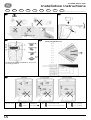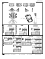
1
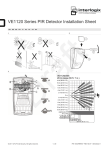
1. Form: 110x200 mm double sided printing, stapled booklet.
2. Fold to fit in box.
1 A 15-05-'07
2 A 2 8 - 11 - ' 0 7
White paper: 75 gr/m, progresso; overprint black.
MANUAL EV1012, EV1012AM and EV1012AMZ
Mikhail Sleptsov
A4
146169999-
17-11-'08
GE Security
110-01
07-683
4 A 11 - 0 7 - ' 0 8
17152664
18499434
5 A 1 7 - 11 - ' 0 8
21555637
3 A 06-05-'08
EV1000 Series PIRs
Installation Instructions
EN
FR
NL
DE
IT
ES
PT
PL
SV
Revision 4.3 (December 2008) • Part number 146169999-5A
!
"
Not pet immune (PI)
#
$
EV1012(AM)(Z)
12 m range (39' 4")
For EN 50131 grade 3 installations, do not use
mounting position C.
%
J1: Not used.
J2:
LED on.
J3 and J4:
LED off.
See Figure '.
J5:
Terminal 8 = D/N.
Terminal 8 = Remote test.
J6:
CV + polarity.
CV - polarity.
www.gesecurity.eu • Copyright © 2008 GE Security B.V. All rights reserved
EV1000 Series PIRs
Installation Instructions
2
&
(7'10")
(2'12")
'
PIR/AM
PIR
PIR/AM
EV1012AMZ
EV1012
EV1012AM
EV1012AM
EV1012
= Control panel
WT = Walk test
AM = Anti-masking
D/N = Day/Night
Rtest = Remote test
EV1000 Series PIRs
Installation Instructions
3
EN Installation instructions
Introduction
The EV1000/1000AM family is made up of PIR/PIR-AM motion
sensors. They have a patented mirror, pyro and signal processing
technology.
Installation guidelines
The technology used in these detectors resists false alarm
hazards. However, avoid potential causes of instability such as
(see Fig. !):
Direct sunlight on the detector.
SW 3: Resetting the AM/TF output
The system will only reset an AM alarm if it has ensured that the
cause of the AM alarm has been removed. If the AM circuitry
cannot return to its original reference levels, then either the
detector is still masked or possibly has been damaged. The owner
should then visually check that the detector is still fully functional.
On: Resets the AM or TF status 40 seconds after a PIR alarm.
Off: Resets the AM or TF status after a PIR alarm when the
system is in Day and Walk Test status. The yellow LED will
blink quickly. When the system is in Night status, the yellow
LED will turn off and the system is reset (ex-factory).
SW 4: Signaling AM or TF output
Heat sources within the detector field of view.
This DIP switch is not used with the AMZ version of
detectors.
Strong draughts onto the detector.
Large animals within the detector field of view.
Objects within 50 cm (20 in.) of the anti-masking (AM)
detector.
Obscuring the detector field of view with large objects, such
as furniture.
Installing two detectors facing each other and less than
50 cm (20 in.) apart.
Installing the detector
1.
Lift off the custom insert and remove the screw (see Fig. ",
step 1).
2.
Using a screwdriver, carefully prise open the detector (see
Fig. ", steps 2 and 3).
3.
Fix the base to the wall between 1.8 m and 3.0 m (5.9 and
9.8 ft.) from the floor. For flat mounting use a minimum of two
screws (DIN 7998) in positions A. For corner-mounting use
screws in positions B or C (Fig. #). To install a pry-off tamper,
use position A or B.
On: Signals AM on both the AM and Alarm relays. Signals TF on
the AM relay only (EN 50131).
Off: Signals AM and TF on the AM relay (ex-factory)
SW 5: Setting LEDs
On: Enables both LEDs on the detector at all times (ex-factory).
Off: Puts both LEDs under the control of the Walk Test and
Day/Night input. This activates the memory feature of the
detector.
LED indication
Continuously on
Normal blinking (1 Hz)
Fast blinking (4 Hz)
PIR
Red
LED
Yellow Alarm AM relay
LED
relay
To reset
Start up
Closed
Automatically after
25 s
Low voltage
Open
(Alarm)
Apply correct voltage
Open
(Alarm)
Automatically after
3s
4.
Wire the detector (see Figs. # and ').
5.
Select the desired jumper and DIP switch settings (see
Fig. %). See section Setting the detector for more information.
PIR intruder
alarm
6.
Remove the blinders and add the stickers, if required (see
Fig. & for an example)
PIR/AM
7.
For ceiling-mount applications that require a 90° coverage
use the SB01 swivel-mount bracket.
Start up
Closed Closed
Automatically after
60 s
8.
Close the cover.
Low voltage
Apply correct voltage
9.
Insert the screw and place the custom insert.
Open Open
(Alarm) (Alarm)
PIR intruder
alarm
Open
(Alarm)
Automatically after
3s
10. For EN 50131 grade 3 installations, do not use mounting
position C.
Setting the detector
Red
LED
See figure % for the jumper locations in the detector.
J1: Not used
Switch toNight mode
Open* Open
(Alarm) (Alarm)
On:
Enables the detector LED at all times (ex-factory).
Off:
Puts the LED under control of the control panel and
disables the detector LED at all times (no memory
feature).
J3 and J4: Dual loop setting
Switch to Night mode
J5: D/N mode (Day/Night) or Rtest (remote test) setting
Do a successful walk
test
Technical specifications
EV1012
EV1012AMZ
PIR
DSP
Range
12 m
Optical
Memory
J6: Polarity setting of the control voltage (CV)
On: “Active High” provides the standard GE Security logic with
“Active High” logic to enable Walk Test (WT) and Day/Night
inputs.
Off: “Active Low” provides “Active Low” logic to enable Walk Test
and Day/Night inputs.
Input power
EV1012AM
PIR + AM
Signal processing
Use this jumper to set terminal 8 to either D/N or Rtest.
GE Security recommends that you use D/N to manage the AM/TF
activation when required. Use Rtest to test the detector from the
control panel. The detector will activate the Alarm relay if the test
result is positive, and the AM relay if the test result is negative.
Terminal 8 = Remote test
Terminal 8 = D/N
Ex-factory
Active Low
Open
(Alarm)
* Depends on the setting of the DIP switch SW4.
Detector
This sets the alarm and tamper relays. It allows you to connect the
detector to any control panel. Use jumpers 3 and 4. See figure '.
See DIP switch 3
After AM
reset
Technical
fault
J2: PIR enabling the LED
To reset
Latched PIR
(Memory)
AM alarm
Jumper settings
Active High
Ex-factory
Yellow Alarm AM relay
LED
relay
9 high-density mirror curtains
No
Yes
9 VDC to15 VDC (12 V nominal)
Peak-to-peak ripple
2 V (at 12 VDC)
Detector start-up time
25 s
Normal current
consumption (mA)
4.4
3.8
10
Current consumption in
Alarm (mA)
1.2
3.9
3.8
Max. current consumption
(mA)
11
24
24
Mounting height
Target speed range
60 s
Min. 1.8 m, max. 3.0 m
(Min. 5.90 ft., max. 9.84 ft.)
30 cm/s to 3 m/s
(1 ft./s to 10 ft./s)
20 cm/s to 3 m/s
(8 in./s to 10 ft./s)
Alarm (NC) / Tamper relay
characteristic
80 mA
30 VDC
SW 1: When to signal AM (anti-masking) or TF (technical fault)
output
Pry-off tamper
Optional
On-board (Yes)
—
80 mA at 30 VDC max.
On: Signals AM or TF only when the system is in Day mode (exfactory).
Alarm time
Off: Always signals AM or TF during Day and Night mode.
Dimensions
(H x W x D)
DIP switch setting
SW 2: AM sensitivity
On: Selects a higher level of AM sensitivity. AM relay reacts within
6 seconds.
Off: Selects the standard AM sensitivity. AM relay reacts within
12 seconds (ex-factory).
AM relay characteristic
Operating temperature
IP/IK rating
80 mA
30 VDC
3s
-10°C to +55°C (14°F to 130°F)
108 × 60 × 46mm (4.25 × 2.36 × 1.81 in.)
Relative humidity
Weight
non
Max. 95%
120 g (4.2 oz.)
128 g (4.5 oz.)
IP30 IK02
EV1000 Series PIRs
Installation Instructions
4
Manuel d’installation
FR
Introduction et compatibilité
Réglage commutateur DIP
SW 1 : Quand signaler les sorties AM (anti-masque) ou PT
(problème technique)
Signale les alarmes AM ou PT uniquement quand le
système est en mode jour (sortie d’usine).
La gamme EV1000 / 1000AM est constituée de détecteurs de
mouvements IRP/IRP-AM. Ceux-ci possèdent une technologie
brevetée de miroir, capteur pyro et traitement du signal. Le
détecteur EV1012AMZ est uniquement utilisable avec les centrales
de la Gamme ATS équipées d’une version de firmware égale ou
supérieure à 04-09-XX (ATS2102/2402/3402/4602) et version 0410-04 pour l’ATS1002.
Activé :
Instructions d'installation
Désactivé : Sélectionne la sensibilité d’anti-masque standard. Le
relais AM réagit en moins de 12 secondes (sortie
d’usine).
La technologie utilisée dans ces détecteurs est conçue pour
résister aux risques de fausses alarmes. Toutefois, il est conseillé
d’éviter les causes d'instabilité potentielles, telles que (voir fig. !) :
L’exposition du détecteur à la lumière directe du soleil.
Les sources de chaleur dans le champ de vision du détecteur.
Les courants d’air puissants sur le détecteur.
La présence de grands animaux dans le champ de vision du
détecteur.
La présence d’objets à moins de 50 cm du détecteur antimasque (AM).
L’obstruction du champ de vision du détecteur par des objets
volumineux, comme des meubles.
L’installation de deux détecteurs face à face à moins de
50 cm de distance.
Installation du détecteur
1.
Soulevez le couvercle et retirez la vis (voir fig. ", étape 1).
2.
A l’aide d’un tournevis, ouvrez délicatement le détecteur en
faisant levier (voir fig. ", étapes 2 et 3).
3.
Fixez la base au mur à une hauteur comprise entre 1,8 m et
3 m du sol. Pour un montage à plat utiliser au minimum deux
vis (DIN 7998) en position A. Pour le montage en coin, utilisez
les vis en positions B ou C (fig. #). Utiliser la position A ou B
pour installer l'autoprotection, pour les modèles avec anti
masque.
4.
5.
Raccordez le détecteur (voir figures # et ') en utilisant un
câble de 3 à 5 paires, en fonction du type de raccordement,
avec ou sans écran et constitué de conducteurs, souples ou
rigides, d’un diamètre de 0.8mm.
Sélectionnez le cavalier requis et la configuration des
commutateurs DIP (voir fig. %). Pour plus d’informations,
consultez la section Réglage du détecteur.
Désactivé : Signale toujours l’AM ou le PT en mode Jour et Nuit.
SW 2 : Sensibilité d’anti-masque
Activé :
Augmente la sensibilité d’anti-masque. Le relais AM
réagit en moins de 6 secondes.
SW 3 : Réinitialisation des sorties AM/PT
Le système réinitialise une alarme AM une fois qu’il est sûr que la
cause de l’alarme AM a été supprimée. Si le circuit AM ne peut pas
revenir à ses niveaux de référence d’origine, soit le détecteur est
toujours masqué, soit il a été endommagé. Le propriétaire doit
alors vérifier physiquement si le détecteur est toujours fonctionnel.
Activé :
Réinitialise l’état AM ou PT 40 secondes après une
alarme IRP.
Désactivé : Réinitialise l’état AM ou PT suite au déclenchement
d’une alarme IRP, lorsque le système est en mode
jour et test de marche. Le témoin jaune clignote
rapidement. Lorsque le système est en état nuit, le
témoin jaune s’éteint et le système se réinitialise
(sortie d’usine).
SW 4 : Signalisation des sorties AM ou PT
Ce commutateur DIP n’est pas utilisé avec la version AMZ
des détecteurs.
Activé :
Signale les sorties AM à la fois sur les relais AM et
d’alarme. Signale les sorties PT sur le relais AM
uniquement (EN 50131).
Désactivé : Signale les sorties AM et PT sur le relais AM (sortie
d’usine).
SW 5 : Réglage des témoins lumineux
Activé :
Active en permanence les deux témoins lumineux du
détecteur (sortie d’usine).
Désactivé : Met les deux témoins sous contrôle des entrées test
de marche et jour/nuit. Ceci active la fonction de
mémoire du détecteur.
Explication des témoins
6.
Retirez les masques et ajoutez les autocollants si nécessaire
(voir fig. & pour exemple).
7.
Pour les applications de montage au plafond requérant une
couverture de 90 °, utilisez la patte de fixation à pivot SB01.
IRP
8.
Fermez le panneau de couverture.
Démarrage
Fermé
9.
Insérez la vis et remettez le couvercle en place.
Automatiquement
après 25 s
Basse tension
Ouvert
(alarme)
Utiliser une tension
correcte
Alarme intrusion
IRP
Ouvert
(alarme)
Automatiquement
après 3 s
10. Pour les installations EN 50131 grade 3, ne pas utiliser le
montage en position C.
Réglage du détecteur
Réglage du cavalier
Allumé en continu
Clignotement rapide (4 Hz)
Témoin Témoin Relais
Relais
rouge jaune d'alarme AM
IRP/AM
Reportez-vous à la figure % pour connaître les emplacements
du cavalier dans le détecteur.
J1 : Non utilisé
J2 : Activation du témoin lumineux avec l'IRP
Témoin Témoin Relais
Relais
rouge jaune d'alarme AM
Fermé
Basse tension
Ouvert
(alarme)
Ouvert Utiliser une tension
(alarme) correcte
Ouvert
(alarme)
Alarme intrusion
IRP
Off
(Désactivé) :
Met le témoin lumineux sous le contrôle de la
centrale et désactive le témoin lumineux du
détecteur (pas de fonction de mémoire).
IRP verrouillé
(mémoire)
Alarme AM
J6 : Réglage de la polarité de tension de contrôle (TC)
Activé :
« Sortie active » fournit la logique GE Security
standard avec une sortie active pour activer les
entrées test de marche et jour/nuit.
Désactivé : « Sortie non active » fournit une sortie non active
pour activer les entrées test de marche et jour/nuit.
Logique active haute
Sortie d’usine
Actif Bas
Automatiquement
après 60 s
Automatiquement
après 3 s
Passer au mode
nuit
Ouvert*
(alarme)
Ouvert Voir commutateur
(alarme) DIP 3
Passer en mode
nuit
Après réinitialisation de l’AM
Ouvert Réussir un test de
(alarme) marche
Problème
technique
J5 : Paramètre du mode J/N (Jour/Nuit) ou du test à distance
Utilisez ce cavalier pour régler le terminal 8 sur J/N ou test à
distance. GE Security recommande l’utilisation de J/N pour gérer
l’activation d’AM/PT quand cela est nécessaire. Utilisez le test à
distance pour tester le détecteur à partir de la centrale. Le
détecteur active le relais d’alarme si le résultat du test est positif
et le relais AM si le résultat du test est négatif.
Terminal 8 = Test à distance
Terminal 8 = J/N
Sortie d’usine
Réinitialisation
Fermé
Active le témoin lumineux du détecteur à tout
moment (sortie d’usine).
J3 et J4 : Configuration de la boucle double
Réinitialisation
Démarrage
On
Activé) :
La boucle double permet de régler les relais d’alarme et
d’autoprotection. Elle permet de connecter le détecteur à tout
type de centrale. Elle utilise les cavaliers 3 et 4. Voir fig. '.
Clignotement normal (1 Hz)
* Dépend du paramétrage du commutateur DIP SW4.
Spécifications techniques
EV1012
Statut
Traitement du signal
Mémoire
EV1012AM
IRP + AM
DSP
Catégorie
Optique
EV1012AMZ
IRP
12 m
9 miroirs à rideau haute densité
Non
Tension d’alimentation
Oui
9 à 15 V CC (12 V nominal)
Ondulation crête à crête
2 V (à 12 V CC)
Temps de démarrage du
détecteur
25 s
60 s
Consommation au repos,
hors alarme (mA)
4.4
3.8
10
Consommation en alarme,
sans activation Led (mA)
1.2
3.9
3.8
EV1000 Series PIRs
Installation Instructions
5
EV1012
Consommation en alarme
avec Led activée (mA)
EV1012AMZ
11
Hauteur de montage
EV1012AM
24
24
Min. 1,8 m, max. 3,0 m
Vitesse cible
De 30 cm/s
à 3 m/s
Caractéristiques du relais
d’alarme (NC) /
d’autoprotection
Protection contre
l’arrachement
80 mA,
30 V CC
De 20 cm/s à 3 m/s
J5: Instelling van D/N-modus (Dag/Nacht) of Rtest (test op
afstand)
non
Met deze jumper kunt u aansluiting 8 op D/N of Rtest instellen.
GE Security raadt aan dat u D/N gebruikt voor het controleren van
de AM/TF-activering, indien nodig. Gebruik Rtest om de detector te
testen vanaf de centrale. De detector activeert het alarmrelais als
het testresultaat positief is en activeert het AM-relais als het
testresultaat negatief is.
Terminal 8 =
Terminal 8 = D/N
Test op afstand
(fabrieksinstelling)
80 mA, 30 V CC
Optionnelle
Oui, d’origine
—
80 mA à 30 V cc max.
Caractéristiques du
relais AM
Temps d’alarme
3s
Température de
fonctionnement
de -10 °C à +55 °C
Dimensions (H x L x P)
108 × 60 × 46 mm
Humidité relative
J6: Polariteitsinstelling van de regelspanning (CV)
Aan: “Actieve hoge” biedt de standaard GE Security-logica met
“Actieve hoge”-logica om de ingangen Looptest (WT) en
Dag/Nacht (D/N) in te schakelen.
95 % max.
Poids
120 g
128 g
Classe IP/IK
IP30 IK02
Angle de détetion NFA2P
79° à 8m
Portée max NFA2P
J3 en J4: Dubbele lusinstelling
Hiermee stelt u de alarm- en sabotagerelais in. U kunt de detector
hiermee op elk controlepaneel aansluiten. Gebruik de jumpers 3
en 4. Zie fig.'.
Uit: “Actieve lage” biedt “Actieve lage”-logica om de ingangen
Looptest en Dag/Nacht in te schakelen.
Actieve hoge
(fabrieksinstelling)
12m
EV1012
: NFA2P grade 2 n° xxxxxx-xx
EV1012AM
: NFA2P grade 3 n° xxxxxx-xx
EV1012AMZ
: NFA2P grade 3 n° xxxxxx-xx
CNPP
B.P. 2265
27950 St Marcel
Tel : 02 32 53 64 22
Instelling DIP-switch
SW 1: Wanneer u AM (anti-maskering) of TF (technische fout)
moet melden
AFNOR
11 rue Pressensé
93571 La Plaine St Denis
Tel : 01 46 11 37 00
Aan:
AM of TF alleen melden wanneer het systeem in de modus
Dag staat uitgeschakeld (fabrieksinstelling).
Uit:
Geeft altijd het signaal AM of TF tijdens Dag- en
Nacht-modus.
SW 2: AM-gevoeligheid
Aan:
NL
Installatie-instructies
Een hoge AM-gevoeligheid selecteren. AM-relais reageert
binnen 6 seconden.
De standaard AM-gevoeligheid selecteren. AM-relais
reageert binnen 12 seconden (fabrieksinstelling).
SW 3: De AM/TF-uitgang resetten
Het systeem zal alleen een AM-alarm resetten als is geconstateerd
dat de oorzaak van het AM-alarm is verwijderd. Als het AM-niveau
niet kan terugkeren naar de oorspronkelijke referentieniveaus, dan
is de detector nog steeds gemaskeerd of is mogelijk beschadigd.
De eigenaar moet vervolgens visueel controleren of de detector
nog steeds volledig functioneel is.
Uit:
Inleiding
De EV1000 / 1000AM-serie bestaat uit PIR / PIR-AMbewegingssensors. Ze zijn voorzien van gepatenteerde spiegel-,
pyro- en signaalverwerkingstechnologie.
Richtlijnen voor de installatie
De technologie in deze detectors maakt het systeem minder
gevoelig voor valse alarmen. Vermijd echter bepaalde situaties die
instabiliteit kunnen veroorzaken, zoals (zie fig. !):
Rechtstreeks zonlicht op de detector.
Warmtebronnen binnen het detectieveld van de detector.
Aan:
Stelt de AM- of TF-status 40 seconden na een PIR-alarm
opnieuw in.
Uit:
De AM- of TF-status wordt gereset na een PIR-alarm, mits
ingesteld op een Dag- en Loopteststatus. De gele lLED
gaat snel knipperen. Als het systeem zich in de stand
Nacht bevindt, gaat de gele LED uit en wordt het systeem
gereset (fabrieksinstelling).
Veel tocht op de detector.
Grote dieren binnen het detectieveld van de detector.
Objecten binnen 50 cm van de AM-detector (anti-maskering).
Het kijkveld van de detector afschermen met grote objecten,
zoals meubels.
Twee detectors recht tegenover elkaar en met minder dan
50 cm tussenruimte installeren.
SW 4: Signalering van AM- of TF-uitgang
Deze DIP-schakelaar wordt niet gebruikt voor de AMZversie van detectors.
Aan:
Antimaskeringssignaal afgeven op zowel het AM-relais als
het alarmrelais. Technische storing alleen melden op het
AM-relais (EN 50131).
Uit:
AM en TF alleen melden op het AM-relais
(fabrieksinstelling).
De detector installeren
11. Til het afdekplaatje omhoog en verwijder de schroef (zie
fig. ", stap 1).
12. Maak
de
detector
voorzichtig
open
schroevendraaier (zie fig. ", stappen 2 en 3).
Actieve lage
met
een
13. Monteer de achter box tegen de muur tussen 1,8 m en 3,0 m
vanaf de vloer. Gebruik voor vlakke montage minimaal twee
schroeven (DIN 7998), in positie A. Gebruik voor hoekmontage
schroeven in de positie B of C (fig. #). Bij installatie van de
afneem sabotage beveiliging gebruik positie A of B.
14. Breng de bedrading van de detector aan (zie fig. # en ').
15. Selecteer de gewenste instellingen voor de jumper en DIPschakelaars (zie fig. %). Zie het gedeelte De detector instellen
voor meer informatie.
SW 5: LEDs instellen
Aan:
Beide leds op de detector blijven permanent ingeschakeld
(fabrieksinstelling).
Uit:
Wanneer het systeem is uitgeschakeld, worden beide leds
geregeld door de ingang Looptest en Dag/Nacht in te
schakelen. Dit activeert de geheugenfunctie van de
detector.
LED-indicatie
Continu aan
Normaal knipperend (1 Hz)
Snel knipperen (4 Hz)
16. Verwijder de spiegelsegment afschermingen kapjes maskers
en breng de stickers aan, indien nodig (zie fig. &).
PIR
17. Als u de detector aan het plafond wilt bevestigen voor een
90° dekking, moet u de SB01-beugel gebruiken.
Opstarten
Gesloten
Automatisch na
25 sec
19. Breng de schroef weer aan en zet het afdekplaatje terug.
Lage
spanning
Open (Alarm)
Correcte spanning
toepassen
20. Voor EN 50131 grade 3 installaties, maak geen gebruik van
montagepositie C.
PIRinbraakalarm
Open (Alarm)
Automatisch na
3 sec
De detector instellen
PIR/AM
18. Plaats het front terug.
Jumperinstellingen
Zie figuur % voor de locatie van de jumpers in de detector.
J1: Niet in gebruik
J2 : PIR voor inschakelen van de LED
Aan:
Schakelt de LED permanent aan (fabrieksinstelling).
Uit:
Plaatst de LED onder de controle van de centrale en
schakelt de LED permanent uit (geen geheugenfunctie).
Rode Gele Alarmrelais
LED LED
Rode Gele Alarmrelais
LED LED
AM-relais
Opnieuw instellen
AM-relais
Opnieuw instellen
gesloten
Automatisch na
60 sec
Opstarten
gesloten
Lage
spanning
Open (Alarm) Open
(Alarm)
Correcte spanning
toepassen
PIRinbraakalarm
Open (Alarm)
Automatisch na
3 sec
Vergrendeld
PIR
(geheugen)
Overschakelen naar
Nacht-modus
EV1000 Series PIRs
Installation Instructions
6
PIR/AM
Rode Gele Alarmrelais
LED LED
AM-alarm
AM-relais
Open* (Alarm) Open
(Alarm)
Na AM-reset
Technische
storing
Open
(Alarm)
Opnieuw instellen
9.
Zie DIPschakelaar 3
10. Bei
EN50131
Grad
3
Installationen
Montageposition C nicht verwendet werden.
Overschakelen naar
Nacht-modus
Einstellen des Melders
Een looptest goed
uitvoeren
* Is afhankelijk van de instelling van dip schakelaar SW4.
EV1012
EV1012AMZ
PIR
EV1012AM
PIR + AM
DSP
Bereik
12 m
Optisch
9 spiegelgordijnen met hoge dichtheid
Aansluitspanning
Nee
Opstarttijd detector
2 V (bij 12 VDC)
25 sec
4.4
3.8
10
Stroomverbruik in
alarmtoestand (mA)
1.2
3.9
3.8
Maximaal stroomverbruik
(mA)
11
24
24
Alarm (NC) /
Sabotagerelais kenmerk
Verwenden Sie diese Steckbrücke, um Anschlussklemme 8
entweder auf D/N oder Rtest einzustellen. GE Security empfiehlt
für die erforderliche Verwaltung der AM/TF-Aktivierung die
Einstellung D/N. Verwenden Sie Rtest, um den Melder von der
Einbruchmeldezentrale aus zu testen. Der Melder aktiviert das
Alarmrelais, wenn das Testergebnis positiv ist. Bei einem
negativen Testergebnis wird das Abdeckungs (AM)-Relais aktiviert.
Min. 1,8 m. en max. 3,0 m
30 cm/s tot
3 m/s
Anschlussklemme 8 = D/N
Werkseinstellung
20 cm/s tot 3 m/s
80 mA
30 VDC
niet
80 mA
30 VDC
Afneembeveiliging
Optioneel
Ingebouwd (Ja)
AM-relais kenmerk
—
80 mA bij 30 VDC max.
Alarmtijd
Omgevingstemperatuur
3 sec
-10°C tot +55°C (14°F tot 130°F)
Afmetingen (H x B x D)
Gewicht
Max. 95%
120 g
Aktiv Low
DIP-Schaltereinstellung
128 g
IP/IK-klasse
Anschlussklemme 8 =
Ferntest
J6: Polaritätseinstellung der Steuerspannung (CV)
Ein: „Aktiv High“ stellt der standardmäßigen GE SecuritySteuerlogik die „Aktiv High“ Logik zur Verfügung, um die
Eingänge für Gehtest (WT) und Scharf/Unscharf zu steuern.
Aus: „Aktiv Low“ die stellt „Aktiv Low“ Logik zur Verfügung, um die
Eingänge für Gehtest und Scharf/Unscharf zu ermöglichen.
Aktiv High
Werkseinstellung
108 × 60 × 46 mm
Relatieve luchtvochtigheid
Die LED wird von der Einbruchmeldezentrale gesteuert
und die Melder-LED ist immer deaktiviert (keine
Speicherfunktion).
J5: Einstellung für D/N-Modus (Scharf/Unscharf) oder Rtest
(Ferntest)
60 sec
Normaal stroomverbruik
(mA)
Bewegingsnelheid
J2: PIR aktiviert die LED
Die Melder-LED ist immer aktiviert (Werkseinstellung).
Ein:
Dient zur Einstellung des Alarm- und Sabotagerelais. Sie können
damit den Melder an eine beliebige Einbruchmeldezentrale
anschließen. Verwenden Sie die Steckbrücken 3 und 4 (Abb. ').
9 VDC tot 15 VDC (12 V nominaal)
Montagehoogte
Siehe Abbildung % für die Steckbrückenpositionen (J1-6) im
Melder.
J3 und J4: Einstellung für Dual-Meldegruppe
Ja
Max rimpelspanning piektot-piek
die
Steckbrückeneinstellungen
Aus:
Signaalverwerking
Geheugen
darf
J1: Nicht verwendet
Technische specificaties
Detector
Setzen Sie die Schraube und die kundenspezifische
Abdeckkappe wieder ein.
SW 1: Wann eine Abdeckungs(AM)- oder Technischer
Fehler(TF)-Ausgabe signalisiert werden sollte
Ein: Signalisiert AM oder TF nur, wenn sich das System im
Tagbetrieb (unscharf) befindet (Werkseinstellung).
IP30 IK02
DE Installationsanweisungen
Aus: Signalisiert AM oder TF immer im Scharf- und
Unscharfbetrieb.
Einführung
SW 2: AM-Empfindlichkeit
Die Serie EV1000-D/1000AM-D besteht aus PIR/PIR-AMBewegungsmeldern. Letztere verfügen über einen patentierten
Spiegel sowie Pyro- und Signalverarbeitungstechnologie.
Ein: Wählt eine höhere Stufe der Abdeckungsempfindlichkeit aus.
AM-Relais reagiert innerhalb von 6 Sekunden.
Installationsanleitungen
Aus: Wählt die Standard-Abdeckungsempfindlichkeit aus.
Große Tiere innerhalb des Erfassungsbereichs des Melders.
AM-Relais reagiert innerhalb von 12 Sekunden
(Werkseinstellung).
SW 3: Zurücksetzen des AM/TF-Ausgangs
Das System setzt einen AM-Alarm nur zurück, wenn er sicher ist,
dass die Ursache des AM-Alarms behoben wurde. Wenn der AMSchaltkreis nicht zu seiner ursprünglichen Referenzebene
zurückkehren kann, ist entweder der Melder noch abgedeckt oder
wurde möglicherweise beschädigt. Der Betreiber sollte dann
nachschauen, ob der Melder noch voll funktionsfähig ist.
Objekte innerhalb von
Abdeckerkennung (AM).
mit
Ein: Setzt den AM- oder TF-Status 40 Sekunden nach einem PIRAlarm zurück.
Verdecken des Erfassungsbereichs des Melders durch große
Objekte, z. B Möbel.
Aus: Setzt den AM- oder TF-Status nach einem PIR-Alarm zurück,
wenn das System in den Unscharf- und Gehtest-Modus
geschaltet wurde. Die gelbe LED wird schnell blinken. Wenn
sich das System im Scharfmodus befindet, erlischt die gelbe
LED-Anzeige und das System wird zurückgesetzt
(Werkseinstellung).
Die in diesen Meldern eingesetzte Technologie dient zur
Vermeidung falscher Alarmmeldungen. Dennoch sollten Sie
potenzielle Instabilitätsfaktoren vermeiden (Abb. !), darunter:
Direkte Sonneneinstrahlung auf den Melder.
Hitzequellen innerhalb des Erfassungsbereichs.
Starke auf den Melder gerichtete Zugluft.
50 cm
des
Melders
Montage zweier gegenüberliegender Melder in einem
Abstand von weniger als 50 cm.
Installation des Melders
1.
Nehmen Sie die kundenspezifische Abdeckkappe ab und
entfernen Sie die Schraube (Abb. ", Schritt 1).
2.
Öffnen Sie den Melder vorsichtig mit einem Schraubendreher
(Abb. ", Schritte 2 und 3).
3.
Befestigen Sie die Basis in einem Abstand von 1,80 m bis 3 m
vom Boden an der Wand. Verwenden Sie bei der
Wandmontage mindestens 2 Schrauben (DIN 7998) in den
Positionen A. Verwenden Sie für eine Eckmontage Schrauben
in den Positionen B oder C (Abb. #). Bei Installation eines
Abreißkontakts, verwenden Sie die Positionen A oder B.
4.
Verkabeln Sie den Melder (Abb. # und ').
5.
Wählen Sie die gewünschten Steckbrücken- und DIPSchaltereinstellungen aus (Abb. %). Weitere Informationen
finden Sie im Abschnitt Einstellen des Melders.
6.
Entfernen Sie die Spiegel-Abdeckungen und bringen Sie bei
Bedarf die Aufkleber an (Abb. & enthält ein Beispiel)
7.
Verwenden Sie für Deckenmontagen, bei der eine
Überwachung von 90° erforderlich ist, den Befestigungssatz
für Wand- und Deckenmontagen (SB01).
8.
Schließen Sie die Abdeckung.
SW 4: Signalisiert AM- oder TF-Ausgang
Dieser DIP-Schalter hat bei AMZ-Melderversionen keine
Funktion.
Ein: Signalisiert AM (Abdeckung) auf dem AM- und auf dem
Alarmrelais. Signalisiert TF nur auf dem AM-Relais (EN 50131).
Aus: Signalisiert AM und TF auf dem AM-Relais (Werkseinstellung).
SW 5: Einstellen von LEDs
Ein: Aktiviert ständig beide LEDs auf dem Melder
(Werkseinstellung).
Aus: Beide LEDs werden durch den Eingang für Gehtest und
durch die Einstellung für Scharf/Unscharf gesteuert.
Dies aktiviert die Speicherfunktion des Melders.
EV1000 Series PIRs
Installation Instructions
7
LED-Anzeige
Installazione del rivelatore
Ständig Ein
Normales Blinken (1 Hz)
Schnell blinkend (4 Hz)
PIR
Rote
LED
Gelbe
LED
Alarmrelais
AMRelais
Geschlossen
Automatisch nach
25 Sek.
Unterspannung
Offen
(Alarm)
Verwenden Sie die
korrekte Spannung
PIREinbruchalarm
Offen
(Alarm)
Automatisch nach
3 Sek.
Rote
LED
Gelbe
LED
Alarmrelais
AMRelais
Zurücksetzen
Start
Geschlossen
Geschlossen
Automatisch nach
60 Sek.
Unterspannung
Offen
(Alarm)
Offen
(Alarm)
Verwenden Sie die
korrekte Spannung
PIREinbruchalarm
Offen
(Alarm)
Automatisch nach
3 Sek.
PIR-Speicher
Schalten Sie 1 x
Scharf/Unscharf
AM-Alarm
Offen*
(Alarm)
Offen
(Alarm)
Siehe DIP-Schalter 3
Schalten Sie 1 x
Scharf/Unscharf
Nach
Zurücksetzen
von AM
Technischer
Fehler
Offen
(Alarm)
Führen Sie einen
erfolgreichen
Gehtest durch
* Abhängig von der Einstellung von DIP-Schalter SW4.
Technische Daten
EV1012-D
Melder
EV1012AMZ
PIR
EV1012AM
PIR + AM
Signalauswertung
DSP
Reichweite
12 m
Optik
9 Spiegelvorhänge mit hoher Dichte
Speicher
Nein
Versorgungsspannung
Meldereinschaltzeit
Ja
9 bis 15 V Gleichspannung (12 V nominal)
Spitze/SpitzeBrummspannung
2 V (bei 12 V Gleichspannung)
25 Sek.
Normale Stromaufnahme
(mA)
4,4
3,8
10
Stromaufnahme bei Alarm
(mA)
1,2
3,9
3,8
Maximale Stromaufnahme
(mA)
11
24
24
Min. 1.8 m, max. 3.0 m
Erfassungsgeschwindigkeitsbereich
Notschalter für
Gehäuseöffnung
Optional
Intern (Ja)
—
80 mA bei 30 V
Gleichspannung max.
Betriebstemperatur
keine
80 mA
30 VDC
3 Sek.
-10 °C bis +55 °C (14 °F bis 130 °F)
Abmessungen (H x B x T)
108 × 60 × 46 mm
Relative Luftfeuchtigkeit
Max. 95 %
Gewicht
IP/IK-Einstufung
3.
Fissare la base al muro ad un'altezza dal pavimento
compresa tra 1,8 e 3 m. Per il fissaggio a parete utilizzare
almeno due viti (DIN7998) nelle posizioni A. Per il montaggio
angolare, utilizzare le viti nelle posizioni B o C (fig. #). Per
installare un contatto antirimozione, utilizzare la posizione A
o B.
4.
Collegare il rivelatore (fig. # e ').
5.
Selezionare le impostazioni desiderate dei ponticelli e dei
commutatori DIP switch (vedere fig. %). Per ulteriori
informazioni, vedere la sezione Impostazione del rivelatore.
6.
Rimuovere la schermatura e applicare gli adesivi secondo
necessità (per un esempio vedere la fig. &).
7.
Per applicazioni con montaggio a soffitto che richiedano una
copertura a 90°, utilizzare il supporto mobile SB01.
8.
Chiudere il coperchio.
9.
Inserire la vite e riposizionare al suo posto la chiusura a
incastro.
120 g
10. Per installazioni l'EN 50131 grado 3, non utilizzare la
posizione C.
Dispositivo antirimozione
EV1012
Su questi modelli il dispositivo antirimozione è opzionale. Inserire il
dispositivo ST400 quando viene richiesta la protezione
antirimozione (per la conformità alle norme CEI 79.2 è obbligatorio
l’utilizzo del kit antirimozione ST400).
EV1012AM, EV1012AMZ
Su questi modelli il dispositivo antirimozione è integrato nel
circuito stampato del rivelatore. Viene attivato con l’apposito pin
riportato in figura # sopra la morsettiera del rivelatore. Per
utilizzare il sistema antirimozione, si deve fissare il rivelatore alla
parete tramite uno dei fori di montaggio indicati con A e B posti
sopra la morsettiera del rivelatore (vedi figura #). Il sistema
antirimozione può essere utilizzato in posizione di montaggio su
parete piana e in una sola posizione di montaggio ad angolo
(Figura #, B).
Impostazione del rivelatore
Impostazioni dei ponticelli
Per le posizioni dei ponticelli nel rivelatore, vedere la figura %.
J1: non utilizzato
Chiuso:
80 mA
30 VDC
Alarmdauer
Aprire il rivelatore facendo leva con un cacciavite (fig. ",
punti 2 e 3).
J2: PIR che attiva il LED
20 cm/Sek. bis 3 m/Sek.
Eigenschaften Alarm- (NC) /
Sabotagerelais
Eigenschaften AM-Relais
2.
Per la conformità alle norme CEI 79.2 è obbligatorio
l’utilizzo della protezione antirimozione.
60 Sek.
Montagehöhe
Sollevare la chiusura a incastro e rimuovere la vite (vedere
fig. ", punto 1).
Zurücksetzen
Start
PIR/AM
1.
128 g
IP30 IK02
IT Istruzioni per l'installazione
Introduzione
La famiglia EV1000 / 1000AM è costituita da rivelatori di
movimento PIR/PIR-AM. Sono dotati di uno specchio brevettato,
sensore pirolettrico ed elaborazione del segnale.
Linee guida per l'installazione
La tecnologia utilizzata per questi rivelatori è a prova di falsi
allarmi. È tuttavia necessario evitare potenziali cause di instabilità,
quali (vedere la fig. !):
Esposizione del rivelatore alla luce solare diretta.
Fonti di calore nel campo visivo del rivelatore.
Forti correnti d'aria in prossimità del rivelatore.
Animali di grosse dimensioni nel campo visivo del rivelatore.
Presenza di oggetti nel raggio di 50 cm dal rivelatore
antimascheramento (AM).
Oscuramento del campo visivo del rivelatore con oggetti di
grandi dimensioni (es. mobilio).
Installazione di due rivelatori l'uno di fronte all'altro a meno di
50 cm di distanza.
Aperto:
attiva il LED del rivelatore (impostazione di
fabbrica).
mette il LED sotto il controllo della centrale
(nessuna funzione memoria).
J3 e J4: impostazione circuito doppio bilanciamento
Imposta i relè di allarme e antimanomissione e consente di
collegare il rivelatore a qualsiasi centrale. Utilizzare i ponticelli 3 e
4. Vedere fig. '.
J5: impostazione del modo D/N (giorno/notte) o Rtest (test
remoto)
Utilizzare questo ponticello per impostare il terminale 8 su D/N o
Rtest. GE Security consiglia di utilizzare D/N per gestire
l'attivazione AM/TF quando necessario. Utilizzare Rtest per testare
il rivelatore dalla centrale. Il rivelatore attiva il relè allarme se il
risultato del test è positivo e il relè antimascheramento se il
risultato del test è negativo.
Terminale 8 =
Terminale 8 = D/N
Test remoto
impostazione di fabbrica
J6: impostazione della polarità della tensione di controllo (CV)
Chiuso: "Attiva alta" fornisce la logica standard GE Security attiva
alta che abilita gli ingressi test di copertura (WT) e
giorno/notte (D/N).
Aperto: "Attiva bassa" fornisce la logica attiva bassa che abilita
gli ingressi test di copertura e giorno/notte.
Attiva alta
Impostazione di fabbrica
Attiva bassa
Impostazione commutatore DIP-switch
SW 1: quando segnalare l'uscita AM (antimascheramento)
o TF (guasto tecnico)
On: segnala l'uscita AM o TF solo quando il sistema è nel modo
giorno (impostazione di fabbrica).
Off: segnala sempre AM o TF durante il modo giorno e notte.
SW 2: sensibilità AM
On: seleziona un elevato livello di sensibilità antimascheramento.
Il relè antimascheramento reagisce entro 6 secondi.
EV1000 Series PIRs
Installation Instructions
8
Off: seleziona la sensibilità antimascheramento standard. Il relè
antimascheramento reagisce entro 12 secondi
(impostazione di fabbrica).
SW 3: reset dell'uscita AM/TF
Il sistema consente il reset di un allarme antimascheramento solo
dopo aver accertato che la causa dell'allarme è stata rimossa. Se i
circuiti antimascheramento non possono tornare ai livelli di
riferimento iniziali, significa che il rivelatore è ancora mascherato
o è possibile che sia stato danneggiato. L'utente deve accertarsi
tramite ispezione visiva della corretta funzionalità del rivelatore.
On: resetta lo stato AM o TF da 40 secondi dopo l’attivazione,
mediante un allarme PIR .
Off: resetta lo stato AM o TF mediante un allarme PIR, quando il
sistema è impostato nello stato giorno e l’ingresso test di
copertura (walk test) è attivato. Il LED giallo lampeggerà
velocemente. Quando il sistema è nello stato notte, il LED
giallo si spegne e il sistema si resetta (impostazione di
fabbrica).
EV1012
Tempo di allarme
On:
segnala AM su entrambi i relè AM e allarme e TF solo sul
relè AM (EN 50131).
Off:
segnala AM e TF solo sul relè AM (impostazione di fabbrica).
SW 5: impostazione dei LED
On:
attiva entrambi i LED del rivelatore in qualsiasi momento
(impostazione di fabbrica).
Off:
mette entrambi i LED sotto il controllo degli ingressi test di
copertura (walk test) e giorno/notte (day/night). Ciò attiva la
funzione di memoria del rivelatore.
Dimensioni (A x L x P)
Approvals
Regno Unito Omologato IMQ II° Livello (per la conformità alle
norme CEI 79-2 è necesssario l'utilizzodel kit antirimozione ST400).
EV1012, EV1012AM, EV1012AMZ
Introducción
La gama EV1000/1000AM está fabricada con sensores de
movimiento PIR/PIR-AM. Cuentan con tecnología patentada de
espejos, sensores piroeléctricos y procesamiento de la señal.
Instrucciones para la instalación
La tecnología utilizada en estos detectores resiste riesgos de
falsas alarmas. Sin embargo, debe evitar posibles causas de
inestabilidad, como por ejemplo (consulte la figura !):
Luz solar directa en el detector.
Fuentes de calor dentro del campo de visión del detector.
Fuertes corrientes de aire sobre el detector.
Oscurecer el campo de visión del detector con objetos de
gran tamaño, como por ejemplo mobiliario.
Relè AM Reset
Automatico dopo 25 s
Bassa
tensione
Aperto
(allarme)
Applicazione della
tensione corretta
Allarme anti
intrusione PIR
Aperto
(allarme)
Automatico dopo 3 s
LED
giallo
Relè di
allarme
Relè AM Reset
Avviamento
Chiuso
Chiuso
Bassa
tensione
Aperto
Aperto
Applicazione della
(allarme) (allarme) tensione corretta
Allarme anti
intrusione PIR
Aperto
(allarme)
PIR
memorizzato
(memoria)
Allarme AM
Automatico dopo 60 s
Aperto* Aperto
Vedere DIP switch 3
(allarme) (allarme)
Commutazione modo
notte
Guasto
tecnico
Aperto
Effettuazione con
(allarme) esito positivo di un
test di copertura
* Dipende dall'impostazione del DIP switch SW4.
Specifiche tecniche
EV1012
Rivelatore
EV1012AMZ
PIR
EV1012AM
PIR + AM
Elaborazione segnale
DSP
Portata
12 m
9 tende a specchio ad alta densità
Memoria
No
Sì
Corrente d'ingresso
9-15 V (12 V nominale)
Ondulazione residua
picco-picco
2 V (a 12 V)
Consumo di corrente
normale (mA)
4,4
3,8
10
Consumo di corrente in
stato di allarme (mA)
1,2
3,9
3,8
Consumo di corrente max.
(mA)
11
24
24
60 s
2.
Usando un destornillador, abra el detector con cuidado
(consulte la figura ", pasos 2 y 3).
3.
Fije la base a la pared a una altura de entre 1,8 m y 3 m del
suelo. Para montaje plano utilice un mínimo de dos tornillos
(DIN 7998) en las posiciones A. Para los montajes en esquinas
los tornillos tienen que colocarse en las posiciones B o C
(figura #). Para instalar un tamper de pared, utilice las
posiciones A o B.
4.
Conecte los cables del detector (consulte las figuras # y ').
5.
Seleccione la configuración de puente e interruptor DIP que
desee (consulte la figura %). Consulte la sección
Configuración del detector para obtener más información.
6.
Retire las máscaras y pegue las etiquetas si es necesario
(consulte la figura & como ejemplo).
7.
Para aplicaciones de montaje en el techo que precisen de
una cobertura de 90º utilice el soporte de montaje
giratorio SB01.
8.
Cierre la carcasa.
9.
Ponga el tornillo en su sitio y vuelva a colocar la tapa de la
carcasa.
10. Para instalaciones EN 50131 grado 3, no utilice la posición C
de montaje.
Configuración de puentes
Consulte la figura % para saber dónde están situados los
puentes en el detector.
Activado:
Activa el LED del detector en todo
momento (programación por defecto).
Desactivado:
Pone el LED bajo control del panel de
control y desactiva el LED del detector en
todo momento (sin función de memoria).
PJ3 y PJ4: Configuración de bucle doble
Da 20 cm/s a 3 m/s
Configura los relés de alarma y tamper. Le permite conectar el
detector a cualquier panel de control. Utilice los puentes 3 y 4.
Consulte la figura '.
no
PJ5: Configuración de modo D/N (Día/Noche) o de Rtest
(prueba remota)
Min. 1,8 m, max. 3,0 m
Relè antimanomissione /
allarme (NC) caratt.
80 mA
30 V
Protezione antirimozione
Opzionale
(ST400)
Su scheda (sì)
—
80 mA a 30 V max
Relè AM caratt.
Levante la tapa de la carcasa retire el tornillo (consulte la
figura ", paso 1).
PJ2: PIR que activa el LED
25 s
Da 30 cm/s
a 3 m/s
1.
PJ1: No se utiliza
Tempo di avvio rivelatore
Velocità di rilevamento
Instalación del detector
Configuración del detector
Caratteristiche ottiche
Altezza di montaggio
Instalar dos detectores uno en frente del otro a menos de
50 cm de distancia.
Automatico dopo 3 s
Commutazione modo
notte
Dopo il reset
AM
IP30 IK02
Objetos a menos de 50 cm del detector antimáscara (AM).
Chiuso
LED
rosso
128 g
Animales de gran tamaño dentro del campo de visión del
detector.
Avviamento
PIR/AM
120 g
Grado di protezione IP/IK
Lampeggio veloce (4 Hz).
Relè di
allarme
Max 95%
Peso
Lampeggiamento normale (1 Hz)
LED
giallo
108 × 60 × 46 mm
Umidità relativa
Indicatori LED
LED
rosso
Da -10°C a +55°C
Certificata da +5°C a + 40°C
ES Instrucciones de instalación
Questo DIP non viene utilizzato con la versione AMZ dei
rivelatori.
PIR
EV1012AM
3s
Temperatura di
funzionamento
SW 4: segnalazione uscita AM o TF
Acceso fisso
EV1012AMZ
80 mA
30 V
Utilice este puente para configurar la terminal 8 como D/N o
Rtest. GE Security recomienda utilizar D/N para administrar la
activación de AM/FT cuando sea necesario. Utilice Rtest para
realizar una prueba del detector desde el panel de control. El
EV1000 Series PIRs
Installation Instructions
9
detector activará el relé de alarma si la prueba da resultados
positivos, y el relé de AM si la prueba da resultados negativos.
Terminal 8 = Prueba
Terminal 8 = D/N
remota
Programación por defecto
EV1012
Detector
EV1012AMZ EV1012AM
PIR
PIR + AM
Procesamiento de la señal
PJ6: Configuración de polaridad del voltaje de control (VC)
Activado:
Especificaciones técnicas
“Activo nivel Alto” proporciona la lógica GE Security
estándar con la lógica "Activo nivel Alto" para
permitir las entradas Prueba de paseo (WT) y
Día/Noche.
Desactivado: “Activo nivel Bajo” proporciona la lógica "Activo
nivel Bajo" para permitir las entradas Prueba de
paseo y Día/Noche.
DSP
Alcance
12 m
Óptico
9 cortinas de espejo de alta densidad
Memoria
No
Alimentación de entrada
Sí
9 a 15 VCC (12 V nominal)
Onda de pico a pico
12 V (a 12 VCC)
Tiempo de arranque del
detector
25 s
Consumo de corriente en
estado normal (mA)
4.4
3.8
10
Consumo de corriente en
alarma (mA)
1.2
3.9
3.8
INTERRUPTOR 1: Para señalar la salida AM (antimáscara) o FT
(fallo técnico)
Señala AM o FT sólo cuando el sistema está en
Activado:
modo Día (programación por defecto).
Consumo máximo de corriente
(mA)
11
24
24
Altura de instalación
Mín. 1,8 m, máx. 3 m
(mín. 5,9 pies, máx. 9,84 pies)
Desactivado: Siempre señala AM o FT en el modo Día y Noche.
Rango de velocidades de
destino
30 cm/s a
3 m/s (1 pie/s
a 10 pies/s)
Característica del relé de
alarma (NC) / tamper
80 mA, 30 VCC
Activo nivel Alto
Activo nivel Bajo
Programación por defecto
Configuración de interruptor DIP
INTERRUPTOR 2: Sensibilidad de AM
Activado:
Selecciona un nivel más alto de sensibilidad de AM.
El relé de AM reacciona a los 6 segundos.
Desactivado: Selecciona la sensibilidad estándar de AM. El relé
de AM reacciona a los 12 segundos (programación
por defecto).
INTERRUPTOR 3: Restablecimiento de la salida AM/FT
El sistema sólo restablecerá una alarma de AM si tiene total
seguridad de que la causa de la alarma de AM se ha eliminado. Si
el circuito de AM no puede volver a sus niveles de referencia
originales, entonces es que el detector aún está enmascarado o
que ha sufrido algún posible daño. En este caso, el propietario
debe examinar el detector y comprobar que aún está totalmente
operativo.
Tamper de pared
Activado:
Rango de IP/IK
Restablece los estados de AM o FT 40 segundos
después de una alarma PIR.
Desactivado: Restablece el estado de AM o FT después de una
alarma PIR si el sistema está en los estados de
Prueba de paseo y Día. El indicador LED amarillo
parpadeará rápidamente. Si el sistema está en
estado Noche, el indicador LED amarillo se
apagará y el sistema se restablecerá
(programación por defecto).
INTERRUPTOR 4: Señalización de salida AM o FT
Señala AM en el relé de AM y el relé de alarma.
Señala FT en el relé de AM solamente (EN 50131).
Indicación LED
Parpadeo normal (1 Hz)
Parpadeo rápido (4 Hz)
LED
Relé de
amarillo alarma
Relé de
AM
Restablecimiento
Inicio
Cerrado
Automáticamente
después de 25 s
Tensión baja
Abierto
(alarma)
Aplicar el voltaje
adecuado
Alarma PIR
de intruso
Abierto
(alarma)
Automáticamente
después de 3 s
PIR/AM
LED
rojo
3s
-10°C a +55°C (14°F a 130°F)
Dimensiones (Al x An x Pro)
108 × 60 × 46 mm
(4,25 × 2,36 × 1,81 pulgadas)
Humedad relativa
Peso
Máx. 95%
120 g
(4,2 onzas)
PT
128 g (4,5 onzas)
IP30 IK02
Instruções de instalação
Introdução
A família EV1000/1000AM é composta por sensores de
movimento PIR/PIR-AM. Incluem um espelho patenteado,
tecnologia piro e de processamento de sinais.
A tecnologia utilizada nestes detectores é resistente a riscos de
falsos alarmes. No entanto, evite potenciais causas de
instabilidade como, por exemplo (consulte a fig. !):
Luz solar directa no detector.
Fontes de calor dentro do campo de visão do detector.
Correntes de ar fortes que incidam no detector.
Animais grandes no campo de visão do detector.
Activa ambos LED en el detector en todo momento
(programación por defecto).
LED
rojo
En la placa (Sí)
80 mA a 30 VCC máx.
Temperatura de
funcionamiento
Objectos a uma distância de 50 cm do detector antimáscara (AM).
Desactivado: Pone a ambos indicadores LED bajo el control de
las entradas Prueba de paseo y Día/Noche. Esto
activa la función de memoria del detector.
PIR
80 mA,
30 VCC
–
Tiempo de alarma
INTERRUPTOR 5: Configuración de indicadores LED
Encendido de forma continua
Ninguna
Opcional
Característica del relé de AM
Desactivado: Señala AM y FT en el relé de AM (programación por
defecto)
Activado:
20 cm/s a 3 m/s
(8 pulgadas/s a 10 pies/s)
Orientações de instalação
Este interruptor DIP no se utiliza en las versiones AMZ de
los detectores.
Activado:
60 s
Que obscurecem o campo de visão do detector com objectos
grandes, tais como mobília.
Instalação de dois detectores virados um para o outro e a
uma distância inferior a 50 cm.
Instalação do detector
1.
Levante o insert personalizado e remova o parafuso
(consulte a fig. ", passo 1).
2.
Inserindo uma chave de parafusos, abra cuidadosamente o
detector (consulte a fig. ", passos 2 e 3).
3.
Prenda a base à parede entre 1,8 m e 3,0 m do solo. Para
montagem normal utilize dois parafusos (DIN7998) na
posição A. Para montagem em canto, utilize os parafusos
nas posições B ou C (fig. #). Para instalação com tamper
contra remoção utilize as posições A ou B.
4.
Ligue o detector (consulte as figs. # e ').
5.
Seleccione o jumper desejado e as configurações DIP switch
(consulte a fig. %). Consulte a secção Configurar o detector
para obter mais informações.
LED
Relé de
amarillo alarma
Relé de
AM
Restablecimiento
Inicio
Cerrado
Cerrado
Automáticamente
después de 60 s
Tensión baja
Abierto
(alarma)
Abierto
(alarma)
Aplicar el voltaje
adecuado
6.
Retire as máscaras e adicione os autocolantes, se necessário
(consulte a fig. & para obter um exemplo)
Alarma PIR
de intruso
Abierto
(alarma)
Automáticamente
después de 3 s
7.
Para aplicações em tectos onde seja necessária uma
cobertura de 90°, utilize o suporte de montagem
rotativo SB01.
8.
Feche a tampa.
9.
Insira o parafuso e substitua o insert personalizado.
PIR cerrado
(memoria)
Alarma AM
Cambio a modo
Noche
Abierto* Abierto
(alarma) (alarma)
*Dependiendo
de
la
microinterruptores SW4.
10. Para instalações EN50131 grade 3, não utilizar a posição de
montagem C.
Cambio a modo
Noche
Después de
restablecer
AM
Fallo técnico
Ver interruptor
DIP 3
Abierto
(alarma)
Realizar una prueba
de paseo con éxito
programacion
de
los
Definir o detector
Definições do jumper
Consulte a figura % para saber quais as localizações do jumper
no detector.
EV1000 Series PIRs
Installation Instructions
10
J1: Não utilizado
PIR/AM
LED
vermelho
J2: PIR que activa o LED
Ligado:
Activa o LED do detector em qualquer altura (de
fábrica).
Desligado:
Coloca o LED sob o controlo do painel de controlo
e desactiva o LED do detector em qualquer altura
(sem função de memória).
J3 e J4: Definição de loop dupla
J5: Modo D/N (Dia/Noite) ou definição Rtest (teste remoto)
Utilize este jumper para definir o terminal 8 para D/N ou Rtest. A
GE Security recomenda que utilize D/N para gerir a activação
AM/TF, se necessário. Utilize Rtest para testar o detector a partir
do painel de controlo. O detector activa o relé de alarme se o
resultado do teste for positivo e o relé AM se o resultado do teste
for negativo.
Terminal 8 = Teste remoto
J6: Definição de polaridade da tensão de controlo (CV)
Ligado:
Desligado:
“Active High” acrescenta a lógica padrão da
GE Security com a lógica “Active High” para activar
as entradas Walk Test (WT) e Dia/Noite.
“Active Low” acrescenta a lógica “Active Low” de
modo a activar as entradas Walk Test e Dia/Noite.
Active High
Active Low
De fábrica
Configuração do DIP switch
SW 1: Quando sinalizar AM (anti-máscara) ou output TF (falha
técnica)
Assinala AM ou TF apenas quando o sistema estiver
Ligado:
no modo Dia (de fábrica).
Desligado:
Assinala sempre AM ou TF durante o modo Dia e
Noite.
SW 2: Sensibilidade AM
Ligado:
Selecciona um nível mais elevado de
sensibilidade AM. O relé AM reage dentro de 6
segundos.
Desligado:
Selecciona a sensibilidade AM padrão. O relé AM
reage dentro de 12 segundos (de fábrica).
SW 3: Repor a saída AM/TF
O sistema repõe apenas um alarme AM depois de garantir que a
causa do alarme AM foi removida. Se não for possível repor o
circuito AM para os níveis originais de referência, o detector
continua com máscara ou provavelmente está danificado.
Em seguida, o proprietário deve inspeccionar visualmente se o
detector continua a funcionar.
Ligado:
Repõe o estado de AM ou TF 40 segundos após um
alarme PIR.
Desligado:
Repõe o estado de AM ou TF depois de um alarme
PIR quando o sistema está no estado Dia e Walk
Test. O LED amarelo começa a piscar rapidamente.
Quando o sistema estiver no estado Noite, o LED
amarelo desliga-se e o sistema é reposto (fora de
fábrica).
SW 4: Sinalizar a saída AM ou TF
Este DIP switch não é utilizado com a versão AMZ dos
detectores.
Relé AM Para repor
Baixa tensão
Aberto
(Alarme)
Alarme contra
intrusos PIR
Aberto
(Alarme)
Aberto
(Alarme)
Aplicar tensão
correcta
Automaticamen
te após 3 s
PIR em latch
(memória)
Mudar para o
modo Noite
Alarme AM
Isto define o relé tamper e de alarme. Isto permite-lhe ligar o
detector a qualquer painel de controlo. Utilize os jumpers 3 e 4.
Consulte a fig. '.
Terminal 8 = D/N
De fábrica
LED
Relé de
amarelo alarme
Aberto*
(Alarme)
Aberto
(Alarme)
Consulte DIP
switch 3
Mudar para o
modo Noite
Depois da
reposição AM
Falha técnica
Aberto
(Alarme)
Efectue um
walk test bem
sucedido
* Depende da configuração do DIP switch SW4.
Especificações técnicas
EV1012
Detector
EV1012AMZ
PIR
EV1012AM
PIR + AM
Processamento de sinais
DSP
Intervalo
12 m
Óptico
9 cortinas de espelho de elevada densidade
Memória
Não
Entrada de alimentação
Sim
9 VDC a 15 VDC (12 V nominal)
Ripple pico a pico
2 V (a 12 VDC)
Tempo de início do detector
25 s
Consumo normal de
corrente (mA)
4,4
3,8
10
Consumo de corrente no
alarme (mA)
1,2
3,9
3,8
Consumo máx. de corrente
(mA)
11
24
24
Altura da instalação
Mín. de 1,8 m, máx. de 3,0 m
Velocidade ao “alvo”
30 cm/s
a 3 m/s
Característica do alarme
(NC) / relé do tamper
80 mA,
30 VDC
Tamper de remoção
Característica de relé AM
60 s
20 cm/s a 3 m/s
não
80 mA,
30 VDC
Opcional
No equipamento (Sim)
—
80 mA a um máx. de 30 VDC.
Hora de alarme
3s
Temperatura de
funcionamento
-10 °C a +55 °C
Dimensões (A x L x P)
108 × 60 × 46 mm
Humidade relativa
Peso
Máx. de 95%
120 g
Classificação de IP/IK
PL
128 g
IP30 IK02
Instrukcja instalacji
Wprowadzenie
Rodzina EV1000/1000AM obejmuje czujki ruchu PIR/PIR-AM. W
czujkach zastosowano opatentowany system luster, detektor
podczerwieni, a także technologię przetwarzania sygnału.
Instalacja - wskazówki
Technologia zastosowana w tych czujkach zabezpiecza je przed
fałszywymi alarmami. Tym niemniej należy unikać potencjalnych
przyczyn niestabilności, takich jak (patrz rys. !):
Ligado:
Sinaliza AM em ambos os relés AM e Alarme. Sinaliza
TF apenas no relé AM (EN 50131).
Światło słoneczne padające bezpośrednio na czujkę.
Desligado:
Sinaliza AM e TF no relé AM (fora de fábrica)
Silne strumienie powietrza skierowane na czujkę.
Źródła ciepła w polu widzenia czujki.
SW 5: Configurar LEDs
Duże zwierzęta w polu widzenia czujki.
Ligado:
Activa ambos os LED no detector em qualquer altura
(fora da fábrica).
Obiekty w odległości do 50 cm (20 cali) od czujki z
układem AM.
Desligado:
Coloca ambos os LEDs sob o controlo da entrada
Walk Test e Dia/Noite. Isto activa a função de
memória do detector.
Przesłonięcie pola widzenia czujki przez duże przedmioty,
takie jak meble.
Indicação do LED
Ligado de forma contínua
Piscar rápido (4HZ)
Começa a piscar normalmente (1 Hz)
PIR
LED
vermelho
LED
Relé de
amarelo alarme
Relé AM Para repor
Arranque
Fechado
Automaticame
nte após 25 s
Baixa tensão
Aberto
(Alarme)
Aplicar tensão
correcta
Alarme
contra
intrusos PIR
Aberto
(Alarme)
Automaticame
nte após 3 s
PIR/AM
Arranque
LED
vermelho
LED
Relé de
amarelo alarme
Relé AM Para repor
Fechado Fechado Automaticamen
te após 60 s
Instalacja dwóch czujek naprzeciw siebie w odległości poniżej
50 cm (20 cali).
Instalacja czujki
1.
Unieś maskownicę i wyjmij śrubę (rys. ", krok 1).
2.
Otwórz czujkę, podważając ją ostrożnie wkrętakiem (rys. ",
krok 2 i 3).
3.
Umocuj podstawę do ściany na wysokości od 1,8 m do 3,0 m
(od 5,9 do 9,8 stopy) od podłogi. W przypadku montażu
płaskiego użyj co najmniej dwóch śrub (DIN 7998) w
pozycjach A. W przypadku montażu narożnego użyj śrub w
pozycji B lub C (rys. #). Jeżeli jest wymagane zainstalowanie
czujnika oderwania od ściany, użyj pozycję A lub B.
4.
Podłącz czujkę (rys. # i ').
5.
Wybierz żądane ustawienia zworek i przełączników DIP
(rys. %). Szczegółowe informacje można znaleźć w części
Konfiguracja czujki.
6.
Zdejmij przesłony i w razie potrzeby dodaj naklejki (przykład:
rys. &).
EV1000 Series PIRs
Installation Instructions
11
7.
W przypadku montażu do sufitu, gdzie wymaga się obszaru
pokrycia o kącie 90°, zastosuj wspornik obrotowy SB01.
PIR
8.
Zamknij pokrywę.
Zwarty
9.
Wsuń śrubę i załóż maskownicę.
Uruchomienie
Automatycznie po
25 s.
Niskie
napięcie
Rozwarty
(alarm)
Zastosuj
prawidłowe
napięcie
Alarm intruza
PIR
Rozwarty
(alarm)
Automatycznie po
3 s.
10. W przypadku instalacji EN50131 stopnia 3 nie należy używać
otworu C do montażu.
Konfiguracja czujki
Ustawienia zworek
PIR/AM
Lokalizacja zworek czujki została przedstawiona na rysunku %.
J1: Nieużywany
J2: Włączenie diody LED detektora podczerwieni
On
(Włączony):
Włącza diodę LED czujki we wszystkich
sytuacjach (ustawienie fabryczne).
Off
(Wyłączony):
Włącza sterowanie diodą LED z centrali
alarmowej i wyłącza diodę LED czujki we
wszystkich innych sytuacjach (brak funkcji
pamięci).
J3 i J4: Ustawienie linii dualnej
Ustawia przekaźniki alarmu i sabotażu. Pozwala na podłączenie
detektora do centrali. Użyj zworek 3 i 4. Patrz rys. '.
J5: Ustawienie trybu D/N (dzień/noc) lub Rtest (zdalny test)
Zworka pozwala ustawić zasick 8 do sterowania trybem D/N lub
Rtest. Firma GE Security zaleca korzystanie z trybu D/N do
sterowania pracą układu AM/TF (w razie potrzeby). Tryb Rtest
umożliwia przeprowadzenie testu czujki z centrali. Czujka
aktywuje przekaźnik alarmu, jeśli wynik testu jest pozytywny lub
przekaźnik AM, jeśli wynik testu jest negatywny.
Styk 8 = Zdalny test
Styk 8 = D/N
Ustawienie fabryczne
J6: Ustawienie polaryzacji napięcia sterującego (CV)
Włączony:
„Aktywny wysoki” zapewnia standardowy dla central
GE Security stan „aktywny wysoki” w celu włączania
wejść testu czujek (WT) oraz wejścia dzień/noc.
Wyłączony: „Aktywny niski” zapewnia stan „aktywny niski” do
włączenia wejść testu czujek oraz wejść dzień/noc.
Aktywny wysoki
Aktywny niski
Ustawienie fabryczne
Ustawienia przełącznika DIP
SW 1: Czas sygnalizacji AM ( maskowania) lub TF (usterka
techniczna) na wyjściu
Włączony:
Sygnalizuje AM lub TF, jeśli system pracuje w trybie
Dzień (ustawienie fabryczne).
Wyłączony: Zawsze sygnalizuje AM lub TF w trybie Dzień i Noc.
SW 2: Czułość AM
Włączony:
Ustawienie wyższej czułości AM. Wyjście AM działa w
czasie 6 sekund.
Wyłączony: Ustawienie standardowej czułości AM. Wyjście AM
działa w czasie 12 sekund (ustawienie fabryczne).
SW 3: Zerowanie wyjścia AM/TF
System wyzeruje alarm AM wyłącznie w sytuacji, kiedy otrzyma
potwierdzenie o usunięciu alarmu AM . Jeśli obwód AM nie może
powrócić do wyjściowych poziomów odniesienia, oznacza to, że
czujka jest nadal maskowana lub została uszkodzona. Użytkownik
powinien wizualnie sprawdzić, czy czujka nadal funkcjonuje.
Włączony:
Zeruje stan AM lub TF po 40 sekundach od
alarmu PIR.
Wyłączony: Zeruje stan AM lub TF po alarmie PIR, kiedy system
pracuje w stanie Dzień i testu czujek. Żółta dioda LED
zacznie szybko migać. Jeśli system pracuje w trybie
Noc, żółta dioda LED zgaśnie, a system zostanie
wyzerowany (ustawienie fabryczne).
SW 4: Sygnalizacja wyjścia AM lub TF
Ten przełącznik DIP nie jest używany w czujkach w
wersji AMZ.
Włączony:
Czerw. Żółta
LED
LED
Sygnalizuje AM zarówno na przekaźniku AM,
jak i Alarm. Sygnalizuje TF tylko na przekaźniku AM
(EN 50131).
Czerw. Żółta
LED
LED
Przekaźnik Przekaźnik Zerowanie
alarmu
AM
Przekaźnik Przekaźnik Zerowanie
alarmu
AM
Uruchomienie
Zwarty
Zwarty
Automatycznie po
60 s.
Niskie
napięcie
Rozwarty
(alarm)
Rozwarty
(alarm)
Zastosuj
prawidłowe
napięcie
Alarm intruza
PIR
Rozwarty
(alarm)
Automatycznie po
3 s.
Zablokowany
PIR (pamięć)
Alarm AM
Przełącz w tryb
Noc
Rozwarty
(alarm)*
Rozwarty
(alarm)
Po zerowaniu
AM
Patrz Przełącznik
DIP 3
Przełącz w tryb
Noc
Usterka
techniczna
Rozwarty
(alarm)
Przeprowadź
prawidłowy test
czujki
* Funkcjonalność zależy od pozycji przełącznika DIP SW4.
Parametry techniczne
EV1012
Czujka
EV1012AMZ
PIR
EV1012AM
PIR + AM
Przetwarzanie sygnału
DSP
Zakres
12 m
Optyka
9 kurtyn lustrzanych o wysokiej gęstości
Pamięć
Nie
Zasilanie
Tak
Napięcie stałe od 9 do 15 V
(nominalnie 12 V)
Dopuszczalne tętnienia
(p-p)
2 V (przy napięciu stałym 12 V)
Czas uruchamiania czujki
25 s
Nominalny pobór prądu (mA)
4.4
3.8
60 s
10
Pobór prądu w stanie
alarmowym (mA):
1.2
3.9
3.8
Maksymalny pobór prądu (mA)
11
24
24
Wysokość montażu
Od 1,8 m do 3,0 m
Zakres prędkości celu
Od 30 cm/s
do 3 m/s
Charakterystyka przekaźnika
Alarm (NC) / Sabotaż
80 mA, 30 V
(stałe)
Brak
Zabezpieczenie przed
oderwaniem
Opcjonalne
Zastosowane (Tak)
—
80 mA przy 30 V (maks.),
prąd stały
Charakterystyka przekaźnika
AM
Od 20 cm/s do 3 m/s
Czas alarmu
80 mA, 30 V
(stałe)
3s
Temperatura działania:
od -10°C do +55°C
Wymiary (S x W x G)
108 × 60 × 46 mm )
Wilgotność względna
Waga:
Maks. 95%
120 g
Klasa IP/IK
128 g
IP30 IK02
SV Installationsmanual
Introduktion
EV1000/1000AM familjen består av PassivIR / PassivIR-AM rörelsedetektorer. De har en patenterad spegel, pyro och
signalbehandling teknik.
Riktlinjer för installation
Den teknik som används i dessa detektorer förebygger falsklarms
risker. Undvik dock att utsätta detektorn för potentiella orsaker till
instabilitet som t.ex. (se bild !):
Wyłączony: Sygnalizuje AM i TF tylko na przekaźniku AM
(ustawienie fabryczne).
Direkt solljus på detektorn.
Värmekällor i detektorns täckningsområde.
SW 5: Konfiguracja diod LED
Kraftigt drag på detektorn.
Włączony: Włącza obie diody LED czujki w każdej sytuacji
(ustawienie fabryczne).
Stora djur i detektorns täckningsområde.
Föremål inom 50 cm av antimaskdetektor (AM).
Wyłączony: Sterowanie dwiema diodami LED zostaje przejęte
przez centralę i wejścia testu czujek i trybu
Dzień/Noc. Uruchamia to funkcję pamięci czujki.
Avskärmning av detektorns täckningsområde med stora
föremål, såsom möbler, skyltar.
Dioda LED
Installera inte två detektorer mot varandra, närmare än
50 cm.
Świeci w sposób ciągły
Miga szybko (4 Hz)
Miga normalnie (1 Hz)
Montering av detektorn
1.
Lyft av luckan och ta bort den bifogade skruven (se bild ",
Steg 1).
2.
Bänd försiktigt med hjälp av en skruvmejsel, öppna detektorn
(se bild ", Steg 2 och 3).
EV1000 Series PIRs
Installation Instructions
12
3.
Montera botten på väggen mellan 1,8 m och 3,0 m från
golvet. För plan montering använd minst två skruvar (DIN
7998), minst en skruv i position A och en i läge B. För
hörnmontering använd skruvar i positionerna B eller C
(bild #). För att installera bortbrytningsskydd använd
position A och B.
4.
Koppla in detektorn (se bild # och ').
5.
Välj önskade byglar och DIP switchinställningar (se bild %).
Se avsnittet ”Inställningar av detektorn” för mer information.
6.
Ta bort maskskydden och sätt dit klisterskydd på spegeln, om
så krävs (se bild & för ett exempel).
7.
Tillämpningar för takmontering som kräver en 90° täckning
använd SB01 vridbart tak-och väggfäste.
8.
Sätt på fronen.
9.
Sätt i skruven och tryck fast luckan.
10. För EN 50131
monteringsläge C.
klass
3
anläggningar,
använd
J1: Används ej
J2: Aktivering av LED
På:
Detektorns LED visar status vid aktivitet
(Fabriksinställning).
Av:
LED är släckt, kan aktiveras fjärr från centralapparat
(inget minnesfunktionen).
J3 och J4: Utgångar för larm- och sabotagerelä
Använd bygel 3 och 4 för att välja brytande funktion eller använda
inbyggda motstånd. Se figur '.
Larm och sabotageutgångarna har en brytande
funktion vid aktivering.
Detektorn använder Inbyggda motstånd för larm- och
slutmotstånd (4,7kOhm var). Anslutning av larmslingan
på skruv 4 och 6 för att få dubbelbalanserad slinga.
J5: Dag/Natt eller Fjärrtest (D/N eller R.test)
Välj med bygel J5 om styringång på anslutningsskruv 8 ska
aktivera Dag/Nattläge eller Fjärrtest.
Detektorn kan ställas i dag- eller nattläge. I nattläge är
Antimask eller Tekniskt fel bortkopplade med DIPswitch 1 I läge PÅ. Skruv 8 = D/N (Fabriksinställning).
GE Security rekommenderar att använda D/N för att
styra AM/TF aktivering.
Använd R.Test (Fjärrtest) för att avprova detektorn fjärr
i från centralapparaten. Detektorn aktiverar Larmrelät
om resultatet lyckas eller aktiverar AM relät om testet
misslyckas. Skruv 8 = Fjärrtest.
J6: Polaritet på styrspänningen
På:
Av:
För att aktivera Gångtest ska en hög styrspänning
(+12V) anslutas till skruv 7 (Walk Test). För att aktivera
Dag/Nattläge/Fjärrtest ska en styrspänning (+12V)
anslutas till skruv 8. (Fabriksinställning).
För att aktivera Gångtest ska en låg spänning (0V)
anslutas till skruv 7 (Walk Test). För att aktivera
Dag/Nattläge/Fjärrtest ska en låg spänning (0V)
anslutas till skruv 8.
DIP-switch inställningen
SW 1: Aktivering av AM- (antimask) eller TF- (tekniskt fel)
utgången
På
Av
På:
Aktiverar AM på både AM- och Larmrelä. Aktiverar TF endast
på AM-relä (EN 50131).
Av:
Aktiverar AM och TF på AM-relä. (Fabriksinställning).
SW 5: Inställning av LED (lysdioder)
På:
Aktiverar både lysdioderna på detektorn vid alla tillfällen
(Fabriksinställning).
Av:
Lysdioder aktiveras av Gångtest och Dag/natt styrning.
Dessa aktiverar minnet i detektorn.
Fast LED
ej
Se figur % för byglarnas placering i detektorn.
Av:
OBS! Denna DIP-switch kan inte användas med AMZversionen av detektorn.
LED indikering
Inställningar av detektorn
På:
SW 4: AM eller TF utgång
Aktivera AM eller TF endast då systemet är i dagläge.
EN 50131-2-2 kompatibel (Fabriksinställning).
Alltid aktiv utgång vid AM eller TF under både dag- och
nattläge.
SW 2: AM känslighet
På
Högre AM känslighet. AM-relä reagerar inom 6 sekunder.
Av
Standard AM känslighet. AM-relä reagerar inom 12 sekunder
(Fabriksinställning).
SW 3: Återställning av AM / TF (tekniskt fel) utgången
PIR
Återställning av AM eller TF-larm sker tidigast efter
40 sekunder och att detektorn detekterat en aktivering
av PIR.
Av:
Den gula lampan blinkar snabbt när detektorn är i Nattläge
vid AM/TF-larm Återställning av AM eller TF-larm sker efter
en aktivering av PIR när detektorn är i Dag och Gångtest
läge och den gula lampan kommer att släckas och
detektorn är återställd. (Fabriksinställning).
Röd Gul Larmrelä
LED LED
Fast blinking (4 Hz)
AM-relä Återställning
Uppstart
Sluten
Automatiskt efter 25 s
Låg spänning
Öppen
(Larm)
Använd rätt
styrspänning
PIR inbrottslarm
Öppen
(Larm)
Automatiskt efter 3 s
PIR/AM
Röd Gul Larmrelä
LED LED
AM-relä Återställning
Uppstart
Sluten
Sluten
Automatiskt efter 60 s
Låg spänning
Öppen
(Larm)
Öppen
(Larm)
Använd rätt
styrspänning
PIR inbrottslarm
Öppen
(Larm)
Automatiskt efter 3 s
Latched PIR
(Minne
AM larm
Växla till Nattläge
Öppen
(Larm)
Öppen
(Larm)
Se DIP-switch 3
Efter AM återställning
Växla till Nattläge
Tekniskt fel
Öppen
(Larm)
Efter en lyckad
gångtest
Tekniska specifikationer
EV1012
Detektor
EV1012AMZ
PIR
DSP
Täckningsområde
12 m
Optik
Minne
EV1012AM
PIR + AM
Signalprocess
9 high-density spegelridåer
Nej
Spänningsmatning
Ja
9-15 VDC (12 V nominellt)
Peak-till-peak rippel
2 V (vid 12 VDC)
Detektorns uppstartstid
25 s
Normal ström-förbrukning
(mA)
4.4
3.8
10
Strömförbrukning i larm (mA)
1.2
3.9
3.8
Max. ström-förbrukning (mA)
11
24
24
Monteringshöjd
60 s
Min 1,8 m, max 3,0 m
Avkänning av rörelsehastighet 30 cm/s till
3 m/s
20 cm/s till 3 m/
Larm (NC) / Sabotage relä
80 mA
30 VDC
Bortbrytningsskydd
Tillval
(ST400)
Ingår (Ja)
—
80 mA vid 30 VDC max.
AM relä
ingen
Larmtid
Vikt
80 mA
30 VDC
3s
Dimensions (H x W x D)
108 × 60 × 46 mm
120
Temperatur
128 g
-10°C to +55°C
Relativ fuktighet
Max. 95%
Miljöklass
II
IP/IK klass
IP30 IK02
Larmklass
Systemet kommer bara att återställa en AM-larm om den har
säkerställt att orsaken till AM-larmet har tagits bort. Om AMövervakningen inte kan återgå till sina ursprungliga
referensnivåer, då är antingen detektorn fortfarande maskerade
eller eventuellt har skadats. Anläggningsskötaren ska sedan
visuellt kontrollera att detektorn fortfarande är fullt fungerande.
På:
Blinkande LED (1 Hz)
6169-5A
3
3
3