1
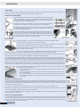
a Instalación $/0$&(1$-( $OUHFLELUODPHUFDQFtDVHGHEHYHULÀFDUTXHpVWDOOHJDHQSHUIHFWDVFRQGLFLRQHVDFRQWLQXDFLyQFRQWURODUTXHORVLWHPVTXHÀJXUDQHQHO albarán coinciden con su pedido, después, cerrar la caja y almacenar a cubierto (Fig. 1). $17(6'(/$I167$/$&IÐ1 $QWHVGHODLQVWDODFLyQGHEHYHULÀFDUVHTXHODVSDUWHVPHWiOLFDVTXHVRSRUWDQHOFRPSHQ sador están de acuerdo con el diseño y plano elaborado a tal efecto, que están libres de proyecciones de soldadura, resaltes o elementos punzantes y, que las zonas de contacto con los tejidos tienen las aristas redondeadas (Fig. 2). Si el espacio entre sectores de contrabrida es mayor de 2 mm, intercalar en la parte inferior, una chapa de 1 mm de espesor y un ancho equivalente al de la contrabrida (Fig. 3). Para juntas de expansión con bridas verticales, el taladro en la contrabrida será avellanado de forma que la cabeza del tornillo, cuando se produce el movimiento axial, no dañe la capa de cobertura del compensador (Fig. 4). Una vez revisados todos estos puntos, se desembalarán las juntas, preferentemente en el lugar en que se vaya a realizar el montaje, si alguna quedase sin instalar, permanecerá en la caja, la cual, quedará cerrada (Fig. 5). En caso de una unidad completa, los dispositivos de DUULRVWUDGR\WUDQVSRUWHQRGHEHQUHWLUDUVHKDVWDODÀQDOL]DFLyQGHOPRQWDMHDVHJXUiQGRVH que son retirados antes de la puesta en marcha (Fig. 6 & 7). I167$/$&IÐ1 &RQHOÀQGHDVHJXUDUXQDFRUUHFWDLQVWDODFLyQVHGHEHUiQWHQHUHQFXHQWDORVVLJXLHQWHVSXQWRV 8QDQGDPLRHQWRGRHOSHUtPHWURGHODMXQWDIDFLOLWDUiODLQVWDODFLyQ En caso de juntas de expansión grandes y pesadas, las cuales no pueden ser trasladadas en su caja al lugar de montaje, se prepara una plataforma para izarlas, en ningún caso directamente (Fig. 8). Durante el montaje, deben ser protegidas de proyecciones de soldadura, elementos punzantes, apoyo de andamios e incluso de caminar sobre ellas. Una vez situada y alineada la junta en su emplazamiento, ésta podrá sujetarse con mordazas, si la junta viene taladrada, la contrabrida y los tornillos se montarán de inmediato, sin apretarlas hasta que toda la junta esté instalada. Una vez terminada esta fase, se apretarán todos los tornillos con una llave dinamométrica al par correspondiente, según el tipo de compenVDGRU(QQLQJ~QFDVRVHGHEHUHWDODGUDUXQDMXQWD\DWDODGUDGDHVWRLPSOLFDUtDODSpUGLGDGHJDUDQWtD En caso de que las juntas vengan sin taladrar, el compensador se situará sobre la brida del conducto, posicionando y alineando correctamente la contrabrida, asegurándola con mordazas apretadas fuertemente, (Fig. 9), para proceder al taladrado (Fig. 10) del compensador para posteriormente introducir el tornillo con su tuerca y arandela, nunca deben realizarse más de dos taladros (una a cada lado de la mordaza); DOLJXDOTXHHQHOFDVRDQWHULRUHODSULHWHGHÀQLWLYRVHKDUiDOÀQDOGHOPRQWDMHGHWRGRHOFRPSHQVDGRUDSOLFDQGRHOSDUFRUUHVSRQGLHQWH 6LODLQVWDODFLyQHVGHXQDXQLGDGFRPSOHWDDQWHVGHVXL]DGRVHGHEHYHULÀFDUTXHHOKXHFRH[LVWHQWHHQWUHFRQGXFWRVVHFRUUHVSRQGHFRQ ODMXQWDGHQRVHUDVtORVGLVSRVLWLYRVGHDUULRVWUDGRGHEHQVHUFRUUHJLGRV(QQLQJ~QFDVRVHXVDUiQGLVSRVLWLYRVGHL]DGRTXHGDxHQODMXQWD En caso de que la junta de expansión vaya acompañada de una bolsa de aislamiento, el procedimiento de instalación dependenderá de este elemento: Si es con bridas, se instalará al mismo tiempo que la junta de expansión, siguiendo las instrucciones dadas anteriormente (Fig. 13). Si es sin bridas, está será colocada en el hueco existente en las partes metálicas, para posteriormente colocar el compensador. Si es aislamiento suelto, éste se retacará en la cavidad, para posteriormente colocar el compensador. Tanto la bolsa de aislamiento como el aislamiento deben llenar completamente el hueco existente en la parte metálica. '(638(6'(/$I167$/$&IÐ1 8QDYH]WHUPLQDGDODLQVWDODFLyQODMXQWDGHEHSURWHJHUVHGHSRVLEOHVDFFLGHQWHVKDVWDODSXHVWDHQPDUFKDFXDQGRpVWDVHSURGXFHVHYHULÀ cará que la junta esté limpia, en perfecto estado y libre de pinchazos que puedan provocar el deterioro acelerado de la misma. A continuación, y teniendo en cuenta las diferencias de compresibilidad de los materiales, acero y textil, se procederá a reapretar los tornillos, no más tarde de una semana tras la puesta en marcha. Los remates del calorifugado son muy importantes para la vida de los compensadores y deben realizarse cuidadosamente. Si la temperatura de los gases está por encima de los 350 ºC, el compensador necesita mayor disipación de calor, por tanto, se usará el remate WLSR´$µ6LODWHPSHUDWXUDHVLQIHULRUD&VHXVDUiHOUHPDWHWLSR´%µ /DVMXQWDVGHH[SDQVLyQWH[WLOHVQRGHEHQVHUFDORULIXJDGDVDH[FHSFLyQGHDTXHOODVHQODVTXHODWHPSHUDWXUDGHOÁXLGRQRVXSHUDORV& y el compensador es un FLEXEL RA. I163(&&IÐ1<0$17(1I0I(172 Las juntas de expansión textiles no necesitan un mantenimiento especial, simplemente se debe controlar si aparecen signos de descomposición HQODFDUDH[WHULRU'HSHQGLHQGRGHOWLSRpVWDVFRPLHQ]DQSRUGHFRORUDUVH\HVFDPDUVHELHQVHDHODWDTXHSRUFDXVDVWpUPLFDVRTXtPLFDVVL DSDUHFHQHVWRVVtQWRPDVGHEHSRQHUVHHQFRQWDFWRFRQSafetech para programar el suministro y montaje de la junta, evitando situaciones de entregas apresuradas con incremento de costes. Installation S725$*( On reception of the materials, verify that boxes or crates arrive in perfect conditions. Then, check that the items on the packing list match WKHSXUFKDVHRUGHU$IWHUFRUUHFWYHULÀFDWLRQFORVHWKHSDFNDJHDQGVWRUHLQDZDWHUSURRIORFDWLRQ)LJ %()25( I1S7$//$7I21 Before installation, verify that the steel parts supporting the expansion joint are in accordance with the design drawings, that they are free from welding projections, edges or cutting elements, and that the areas in contact with the materials have the edges rounded off (Fig. 2). ,IWKHVSDFHEHWZHHQEDFNÁDQJHVLVKLJKHUWKDQPPDPPWKLFNSODWHZLWKWKHVDPH ZLGWKDVWKHEDFNÁDQJHPXVWEHORFDWHGLQWKHERWWRP)LJ )RUH[SDQVLRQMRLQWVZLWKYHUWLFDOÁDQJHVKROHVLQWKHEDFNÁDQJHPXVWEHFRXQWHUVXQN such that the head of the bolt does not damage the expansion joint cover when axial movement occurs (Fig. 4). 2QFHDOOWKHDERYHSRLQWVKDYHEHHQYHULÀHGWKHH[SDQVLRQMRLQWVPD\EHXQSDFNHGSUH ferably at the same location where the installation will take place. If any of the expansion joints remain uninstalled, they shall be kept in the package, which shall be closed (Fig. 5). In the case of complete units, the bracing and transport devices must not be removed until the end of the assembly, but there must be assurance that they are all removed before initial start-up of the system. (Figs. 6 & 7). I1S7$//$7I21 In order to assure a correct installation, the following points must be observed: A scaffolding around the entire perimeter of the expansion joint will facilitate the installation. ,QWKHFDVHRIODUJHRUKHDY\H[SDQVLRQMRLQWVWKDWFDQQRWEHPRYHGLQVLGHWKHLUSDFNLQJXSWRWKHLUÀQDOORFDWLRQ a platform shall be used to lift them. Never lift expansion joints directly (Fig. 8). During the installation, the expansion joints must be protected from welding projections, cutting elements and scaffolding supports. Never walk on the expansion joints. 2QFHWKHH[SDQVLRQMRLQWKDVEHHQSODFHGDQGDOLJQHGLQLWVÀQDOSRVLWLRQÀ[LWZLWKFODPSV2ULIWKHMRLQWLV GHOLYHUHGSUHGULOOHGPRXQWWKHEDFNÁDQJHDQGLQVHUWWKHEROWVZLWKRXWWLJKWHQLQJXQWLOWKHH[SDQVLRQMRLQWLVFRPSOHWHO\LQVWDOOHG :KHQWKLVSKDVHLVÀQLVKHGDOOEROWVZLOOEHWLJKWHQHGZLWKWKHFRUUHVSRQGLQJWRUTXHNH\,QQRFDVHDGULOOHGH[SDQVLRQMRLQWVKDOOEHGULOOHG again, as this will result in the loss of the guarantee. ,IWKHH[SDQVLRQMRLQWLVGHOLYHUHGZLWKQRKROHVLWZLOOEHSRVLWLRQHGRYHUWKHGXFWÁDQJHDOLJQLQJLWFRUUHFWO\DJDLQVWWKHEDFNÁDQJHDQG assuring it with strongly tightened clamps, (Fig. 9), in order to proceed with the drilling of the expansion joint (Fig. 10). Subsequently, the bolt, QXWDQGZDVKHUVKDOOEHLQVWDOOHG1HYHUGULOOPRUHWKDQWZRKROHVRQHRQHLWKHUVLGHRIWKHFODPS$VLQWKHSUHYLRXVFDVHWKHGHÀQLWLYH torque will be applied at the end of expansion joint assembly (Fig. 11). If a complete unit, with steel frames assembled, is to be installed, check the space available between ducts before lifting the expansion joint. If the spaces do not match, the lifting devices must be corrected. Never use lifting devices that might damage the expansion joint (Fig. 12). If the expansion joint includes an insulation bag /bolster, the installation procedure may vary depending on that element: ,ILWLVDÁDQJHGEROVWHULWZLOOEHLQVWDOOHGDWWKHVDPHWLPHDVWKHH[SDQVLRQMRLQWIROORZLQJWKHDERYH instructions (Fig. 13). ,IWKHEROVWHUKDVQRÁDQJHVLWZLOOEHORFDWHGLQWKHVSDFHH[LVWLQJEHWZHHQWKHVWHHOSDUWVDQGODWHUWKH expansion joint will be assembled. ,ILWLVORRVHÀOOLQVXODWLRQWKLVZLOOEHÀWWHGDQGFRPSDFWHGLQWKHVSDFHDQGWKHQWKHH[SDQVLRQMRLQWZLOO be installed. %RWKWKHEROVWHUDQGWKHLQVXODWLRQOD\HUPXVWFRPSOHWHO\ÀOOWKHVSDFHH[LVWLQJLQWKHVWHHOSDUW $)7(5 I1S7$//$7I21 On completion of the installation, the expansion joint shall be protected against any possible accidents until the start-up of the system. At WKLVPRPHQWWKHH[SDQVLRQMRLQWPXVWEHYHULÀHGWREHFOHDQLQSHUIHFWFRQGLWLRQDQGIUHHIURPDQ\FXWWKDWPD\FDXVHIDLOXUH7KHQDQG considering the different compressibility of steel and fabric materials, the bolts shall be retightened no later than one week following start-up. The lagging is very important for the life of the expansion joint and shall be carried out carefully. If the temperature of the gases is higher than 350 ºC, the expansion joint will need a higher protection against heat, and therefore Type A lagging will be used. If the temperature is lower than 350 ºC, Type B lagging will be used. 7KHIDEULFH[SDQVLRQMRLQWVVKDOOQRWEHODJJHGH[FHSWZKHUHWKHÁXLGWHPSHUDWXUHGRHVQRWUHDFK&DQGWKHH[SDQVLRQMRLQWLVD)/(;(/ RA type. I1S3(&7I21 $1' 0$I17(1$1&( )DEULFH[SDQVLRQMRLQWVGRQRWQHHGDQ\VSHFLDOPDLQWHQDQFHRWKHUWKDQVLPSOHYHULÀFDWLRQRIWKHH[WHUQDOOD\HUWRFKHFNIRUGHFRPSRVLWLRQ Depending on the type of expansion joint, the external layer may start losing its original colour or develop scales due either to thermal attack or chemical attack. If these symptoms appear, it will be necessary to contact Safetech in order to schedule the supply and installation of the expansion joint, avoiding urgent delivery situations with the corresponding increase in cost.