1
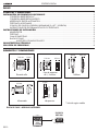
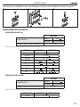
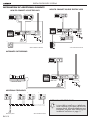
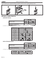
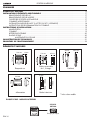
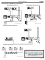
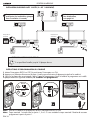
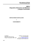
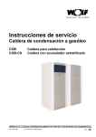
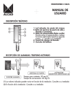
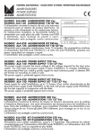
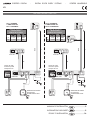
PORTERO DIGITAL
-
DIGITAL DOOR ENTRY SYSTEMS
-
PORTIER NUMÉRIQUE
KITS
TED-001
GRF-200
Tabla de secciones
Section table
Tableau de sections
D1
D2
KIT 2 VIVIENDAS
2 DWELLINGS KIT
KIT 2 LOGEMENTS
D1
D2
KIT 1 VIVIENDA
1 DWELLING KIT
KIT 1 LOGEMENT
ALC-041
Tabla de secciones
Section table
Tableau de sections
TED-001
TED-001
AWG
Dist.
AWG
Dist.
A
1 mm2
17
100m
A
1 mm2
17
100m
B
1 mm2
17
25m
B
1 mm2
17
25m
D1
D2
~
ALC-041 ~
–+ –+
A
230V
~
ALC-041 ~
–+ –+
B
Placa de calle
Entrance panel
Plaque de rue
–+
9 10
12
S
C 11
1
–+
7 D1 D2 D3
8 7 6 5 4 3 2 1
GRF-200
ABR-015
A
B
Placa de calle
Entrance panel
Plaque de rue
+–
BUS
230V
BUS
TED-001
9 10
12
S
C 11
1
7 D1 D2 D3
8 7 6 5 4 3 2 1
GRF-200
APERTURA DE PUERTA
EXIT BUTTON
OUVRE-PORTE LOCAL
+–
APERTURA DE PUERTA
EXIT BUTTON
OUVRE-PORTE LOCAL
ABR-015
MANUAL DE INSTALACIÓN
....................2
INSTALLATION DATA SHEET
....................9
FEUILLE D’INSTALLATION
..................16
PORTERO DIGITAL
ÍNDICE
ELEMENTOS Y DIMENSIONES .................................................................................................................... 2
INSTALACIÓN DE ELEMENTOS ADICIONALES ......................................................................................... 3
CONEXIÓN ABREPUERTAS AC ............................................................................................................. 3
CONEXIÓN ABREPUERTAS INVERSO ................................................................................................... 3
APERTURA DE PUERTA AUTOMÁTICA ................................................................................................... 3
TELÉFONOS ADICIONALES .................................................................................................................. 3
2 PLACAS DE CALLE EN VIVIENDA UNIFAMILIAR (2 x KIT 1 VIVIENDA) ................................................. 4
INSTRUCCIONES DE PROGRAMACIÓN DE LOS TELÉFONOS ................................................................ 4
INSTRUCCIONES DE INSTALACIÓN ........................................................................................................... 5
ALIMENTADOR .................................................................................................................................... 5
TELÉFONO .......................................................................................................................................... 5
CAJA DE EMPOTRAR ........................................................................................................................... 6
PLACA DE CALLE.................................................................................................................................. 6
AJUSTE DEL VOLUMEN DE AUDIO ........................................................................................... 6
CARACTERÍSTICAS TÉCNICAS ..................................................................................................................... 7
SOLUCIÓN DE PROBLEMAS ....................................................................................................................... 8
ELEMENTOS Y DIMENSIONES
84 mm
12 mm
Caja de empotrar
de 1, 2 alturas.
31 mm
B1 B2 B2 B3
3 mm
Alimentador
Abrepuertas
* Incluido según modelo
PLACA DE CALLE - MÓDULOS INTERIORES
9610018
GRF-200
Grupo fónico
ESP-2
Teléfono
160 mm
*
100 mm
230 V
60 mm
30 mm
106 mm
90 mm
224 mm
131 mm
ARRIBA
UP
HAUT
Placa de calle
50.6 mm
45 mm
114 mm
147 mm
128 mm
PORTERO DIGITAL
INSTALACIÓN DE ELEMENTOS ADICIONALES
CONEXIÓN ABREPUERTAS INVERSO
CONEXIÓN ABREPUERTAS AC
*
230V
ALC-041
~
~
230V
~
ALC-041 ~
230V
–+ –+
~
ALA-040 ~
–+ –+
–+
9 10
12
7 D1 D2 D3
9 10
12
S
C 11
1
7 D1 D2 D3
8 7 6 5 4 3 2 1
GRF-200
8 7 6 5 4 3 2 1
GRF-200
*
ASC-050
*
*
Ctrl1
Ctrl2
–+
S
C 11
1
–+
15 V .
500mA
* No incluido en el Kit
ABR-001
* No incluido en el Kit
APERTURA DE PUERTA AUTOMÁTICA
230V
ALC-041
~
~
–+ –+
–+
9 10
12
S
C 11
1
7 D1 D2 D3
8 7 6 5 4 3 2 1
GRF-200
Puerta automática
TELÉFONOS ADICIONALES
TED-001
BUS
Placa de calle
TED-001
TED-001
D1
D2
*
D1
D2
*
D1
D2
D1
D2
*
TED-001
AMPLIACIÓN CON TELÉFONOS:
Es posible instalar un total de hasta 4
teléfonos que respondan a una misma
llamada de la placa de calle. Una vez
conectados, prográmelos tal y como se
explica en la página 4 de este manual.
* No incluido en el Kit
ESP-3
PORTERO DIGITAL
230V
Deberá volver a programar
uno de los teléfonos,
consulte página XX
TED-001
230V
–+ –+
~
ALC-041 ~
Placa de calle
principal
TED-001
D1
D2
Sólo debe haber una placa
principal por instalación (Puente
J1 colocado)
D1
D2
2 PLACAS DE CALLE EN VIVIENDA UNIFAMILIAR (2 x KIT 1 VIVIENDA)
ALC-041
Placa de calle
Secundaria
J1
–+
9 10
12
S
C 11
1
~
~
–+ –+
J1
–+
7 D1 D2 D3
8 7 6 5 4 3 2 1
GRF-200
9 10
12
S
C 11
1
7 D1 D2 D3
8 7 6 5 4 3 2 1
GRF-200
+–
+–
ABR-015
ABR-015
AMPLIACIÓN CON PLACAS DE CALLE:
Es posible instalar un máximo de 10 placas de calle.
INSTRUCCIONES DE PROGRAMACIÓN DE LOS TELÉFONOS
1. Desplace el interruptor PROG a la posición OFF; Vuelva a poner el interruptor en la posición ON.
2. Pulse el botón de abrepuertas. Se activará el audio entre el teléfono y la placa principal.
3. Situado en la placa de calle principal, realice la llamada a la vivienda donde está situado el teléfono a programar.
La placa emitirá un sonido de confirmación, el teléfono ha sido programado.
1
2
3
PROG
1
2
OFF
PROG
ON
PROG
Nota: Una vez programado el teléfono, asegúrese de que el interruptor PROG queda en posición ON.
Nota: Tiempo máximo de 1 minuto entre los pasos 1, 2 y 3. Pasado el tiempo máximo deberá iniciar la programación
desde el paso 1.
ESP-4
PORTERO DIGITAL
INSTRUCCIONES DE INSTALACIÓN
ALIMENTADOR
Consulte las instrucciones de seguridad al final del presente documento. Proteja el alimentador, cumpliendo con la
normativa vigente en materia de instalaciones eléctricas (magneto térmicos, diferenciales...).
1A Montaje a pared
1B Montaje en carril DIN
2
3
TELÉFONO
1
2
3
2
1
4
5
ESP-5
PORTERO DIGITAL
CAJA DE EMPOTRAR
Rompa el tabique de las aberturas que requiera para pasar los cables, y coloque la caja de empotrar de modo que
la parte superior quede a una altura de 1,7 m.
1
2
1,7 m
PLACA DE CALLE
Coloque Las tarjetas identificadoras de los pulsadores de la placa de calle, introduzca las anillas de la placa sobre las
bisagras de la caja de empotrar y realice las conexiones eléctricas.
1
2
3
TARJETAS IDENTIFICADORAS DE LOS PULSADORES:
Puede utilizar las tarjetas preimpresas que se suministran o utilizar la plantilla que encontrará
en la página Web de Alcad: www.alcad.net, dentro del apartado Soporte técnico.
Realice una llamada de prueba y ajuste el volumen de audio de la placa de calle y de los teléfonos.
4
5
Volumen
En placa
En teléfonos
ESP-6
6
Regulador acoplamiento acústico
PORTERO DIGITAL
Cierre la placa, presionándola contra la caja de empotrar y fíjela a la misma mediante los tornillos de sujeción.
7
8
9
CARACTERÍSTICAS TÉCNICAS
GRUPO FÓNICO GRF-200
GRF-200
Tensión:
ALIMENTACIÓN:
15 V
Corriente:
TEMPERATURA DE FUNCIONAMIENTO:
650 mA (máx.)
-10.. +55 OC
TENSIONES USUALES SEGÚN EL ESTADO DEL EQUIPO
BORNAS
REPOSO
+,–
TRABAJO
15 V
±10%
D1, D2
10 - 12 V
D3, D2
10 - 12 V
22, 11
SC1, 11
15 V
4,5 V
7, 11
12, 11
0V
±10%
0V
5V
±10%
±10%
0V
15 V
±10%
, 12
TELÉFONO DIGITAL TED-001
TED-001
Tensión:
ALIMENTACIÓN:
10-12 V
Corriente:
TEMPERATURA DE FUNCIONAMIENTO:
200 mA (máx.)
+5.. +55 OC
TENSIONES USUALES SEGÚN EL ESTADO DEL EQUIPO
BORNAS
D1, D2
REPOSO
TRABAJO
10 - 12 V
ESP-7
PORTERO DIGITAL
ALIMENTADOR ALC-041
ALC-041
ALIMENTACIÓN DE RED:
Tensión:
230 V~ ±10% 50/60Hz
Potencia:
25 VA
Tensión:
SALIDA 1:
15 V
Corriente:
Tensión:
SALIDA 2:
15 V
Corriente:
TEMPERATURA DE FUNCIONAMIENTO:
±10%
0.8 A (máx.)
±10%
0.8 A (máx.)
-10.. +55 OC
SOLUCIÓN DE PROBLEMAS
No funciona nada
Verifique la tensión de red en el alimentador.
Verifique que la tensión entre + y – del alimentador
sea 17 ± 10% Vdc. Compruebe si existe algún
cortocircuito y soluciónelo. Desconecte el
alimentador de la red durante 1 minuto y vuelva a
conectarlo. Si la avería continúa, desconecte todas
las bornas + y – del alimentador, y verifique que
la tensión entre + y – sea 21 ± 10% Vdc. Si no es
correcta el alimentador puede estar averiado.
No se ilumina el piloto del pulsador de
iluminación
Verifique que la tensión entre + y – del grupo fónico
sea 17 ± 10% Vdc. Si la tensión es correcta, el
grupo fónico puede estar averiado.
No se iluminan los tarjeteros
Verifique que la tensión entre + y – del alimentador
sea 17 ± 10% Vdc. Verifique que la tensión entre 9 y
10 del grupo fónico, con el pulsador de iluminación
accionado, sea 17 ± 10% Vdc. Compruebe que la
lámpara no esté fundida.
La placa de calle no emite ningún sonido
al llamar
Revise las conexiones entre el grupo fónico y los
pulsadores. Si no detecta el fallo, el grupo fónico
puede estar averiado.
Si la placa emite tonos intermitentes al
llamar
La llamada no ha sonado en el teléfono: Compruebe
que el auricular está colgado. Compruebe que el
interruptor de programación del teléfono está en la
posición ON (a la izquierda). Revise la conexión
D1, D2 del grupo fónico hacia los teléfonos. Si es el
caso, revise las conexiones D3, D2 de los equipos
de la instalación. Si no detecta el fallo, el teléfono o
el grupo fónico pueden estar averiados.
No se oye ningún teléfono desde la placa de calle
Compruebe el ajuste del regulador de volumen
de audio en placa. Si no detecta el fallo, el grupo
fónico puede estar averiado.
No se oye un teléfono desde la placa de
calle
Revise las conexiones del cable entre el auricular
y la base del teléfono. Compruebe el pulsador de
colgado de la base del teléfono. Si no detecta el
fallo, el teléfono puede estar averiado.
El sonido se acopla.
Ajuste el regulador de desacoplo del grupo fónico
(vea página 6). Si el acoplo persiste baje el volumen
de sonido mediante los reguladores de volumen del
grupo fónico.
Suena la llamada en los teléfonos pero
en la placa de calle no se oye la confirmación de llamada
No funciona el abrepuertas
Si el led rojo de la placa parpadea continuamente
En instalaciones de múltiple acceso, llamando en una de las placas de calle no
se inhabilitan el resto de placas del sistema.
Compruebe el ajuste del regulador de volumen
de audio en placa. Si no detecta el fallo, el grupo
fónico puede estar averiado.
Verifique que ha definido una sola placa de
calle como principal. Compruebe si existe algún
cortocircuito en las conexiones D1, D2 del grupo
fónico hacia teléfonos. Si es el caso, revise las
conexiones D3, D2 de los equipos de la instalación.
Si no detecta el fallo, el grupo fónico puede estar
averiado.
ESP-8
Con el puente entre las bornas 10 y , verifique
que la tensión entre las bornas 12 y 11 del grupo
fónico, sea 17 ± 10% Vdc, realizando un puente
entre las bornas 22 y 11. Si no detecta el fallo, el
abrepuertas puede estar averiado.
Compruebe las conexiones D3, D2 entre las
diferentes placas del sistema. Si no detecta el fallo,
el grupo fónico puede estar averiado.
DIGITAL DOOR ENTRY SYSTEMS
INDEX
ELEMENTS AND DIMENSIONS ................................................................................................................... 9
INSTALLATION OF ADDITIONAL ELEMENTS ........................................................................................... 10
HOW TO CONNECT AC ELECTRIC LOCK ........................................................................................... 10
HOW TO CONNECT INVERSE ELECTRIC LOCK ................................................................................... 10
AUTOMATIC DOOR OPENING ........................................................................................................... 10
ADDITIONAL TELEPHONES................................................................................................................. 10
INSTALLATION IN DETACHED HOUSES WITH 2 POINTS OF ENTRY (2 X 1 DWELLING KIT) ................... 11
TELEPHONE PROGRAMMING INSTRUCTIONS .................................................................................... 11
INSTALLING INSTRUCTIONS .................................................................................................................... 12
POWER SUPPLY UNIT ......................................................................................................................... 12
TELEPHONE ....................................................................................................................................... 12
FLUSH MOUNTED BOX ...................................................................................................................... 13
ENTRANCE PANEL ............................................................................................................................. 13
ADJUSTING THE VOLUME ..................................................................................................... 13
TECHNICAL CHARACTERISTICS................................................................................................................. 14
TROUBLE SHOOTING ................................................................................................................................ 15
ELEMENTS AND DIMENSIONS
84 mm
114 mm
131 mm
ARRIBA
UP
HAUT
Flush-mounted box
of 1, 2 storeys.
*
31 mm
B1 B2 B2 B3
3 mm
Power supply
Telephone
160 mm
230 V
60 mm
100 mm
90 mm
106 mm
30 mm
Entrance panel
50.6 mm
45 mm
224 mm
12 mm
147 mm
128 mm
Lock release
* On certain models only
ENTRANCE PANEL - INSIDE MODULES
9610018
GRF-200
Audio unit
ENG-9
DIGITAL DOOR ENTRY SYSTEMS
INSTALLATION OF ADDITIONAL ELEMENTS
HOW TO CONNECT INVERSE ELECTRIC LOCK
HOW TO CONNECT AC ELECTRIC LOCK
*
230V
ALC-041
~
~
230V
~
ALC-041 ~
230V
–+ –+
~
ALA-040 ~
–+ –+
–+
9 10
12
7 D1 D2 D3
9 10
12
S
C 11
1
7 D1 D2 D3
8 7 6 5 4 3 2 1
GRF-200
8 7 6 5 4 3 2 1
GRF-200
*
ASC-050
*
*
Ctrl1
Ctrl2
–+
S
C 11
1
–+
15 V .
500mA
* Not included in the Kit
ABR-001
* Not included in the Kit
AUTOMATIC GATE OPENING
230V
ALC-041
~
~
–+ –+
–+
9 10
12
S
C 11
1
7 D1 D2 D3
8 7 6 5 4 3 2 1
GRF-200
Automatic Gate
ADDITIONAL TELEPHONES
TED-001
BUS
Entrance panel
ENG-10
TED-001
TED-001
D1
D2
*
D1
D2
*
D1
D2
D1
D2
*
TED-001
EXTENSION WITH TELEPHONES:
It is possible to install up to 4 telephones
which respond to the same call from the
entrance panel. When the telephones are
connected, program them following the
installation instructions in page 11.
* Not included in the Kit
DIGITAL DOOR ENTRY SYSTEMS
230V
You will have to re-program
one of the telephones,
see page 14
TED-001
230V
–+ –+
~
ALC-041 ~
Main entrance
panel
TED-001
D1
D2
An installation must have only
one main entrance panel (panel
with the jumper J1 installed)
D1
D2
INSTALLATION IN DETACHED HOUSES WITH 2 POINTS OF ENTRY (2 x 1 DWELLING KIT)
ALC-041
~
~
–+ –+
Secondary entrance
Panel
J1
J1
–+
9 10
12
S
C 11
1
–+
7 D1 D2 D3
8 7 6 5 4 3 2 1
GRF-200
9 10
12
S
C 11
1
7 D1 D2 D3
8 7 6 5 4 3 2 1
GRF-200
+–
+–
ABR-015
ABR-015
EXTENSION WITH ENTRANCE PANELS:
It is possible to install up to 10 entrance panels.
TELEPHONE PROGRAMMING INSTRUCTIONS
1. Turn the PROG switch to the OFF position; Turn the switch back to the ON position.
2. Push the lock release button. The audio will be activated between the telephone and the main panel.
3. From the main entrance panel, make the call to the apartment where the telephone to be programmed is installed.
The panel emits a confirmation tone, the telephone has been programmed.
1
2
3
PROG
1
2
OFF
PROG
ON
PROG
Note: Once the telephone has been programmed, leave the PROG switch to the ON position.
Note: Maximum time limit of 1 minute between steps 1, 2 and 3. If the time limit is exceeded the process must be
repeated from step 1.
ENG-11
DIGITAL DOOR ENTRY SYSTEMS
INSTALLING INSTRUCTIONS
POWER SUPPLY UNIT
See the safety instructions at the end of this booklet. Protect the power supply unit by complying with existing regulations
governing electrical installations (avoid high-temperature locations and strong magnetic fields, ensure correct fusing,
etc.).
1A Mounting on a wall
1B Mounting on a DIN rail
2
3
TELEPHONE
1
2
3
2
1
4
ENG-12
5
DIGITAL DOOR ENTRY SYSTEMS
FLUSH MOUNTED BOX
Break off the perforated holes that you need to pass the cables through, and place the flush-mounted box in position
so that the top is 1.7 m high.
1
2
1,7 m
ENTRANCE PANEL
Insert the pushbutton identification cards; place the rings of the entrance panel over the extracted fixing pins of the
flush mounted box and make the electrical connections.
1
2
3
PUSHBUTTON IDENTIFICATION CARDS:
You can use either the preprinted cards which are provided or print your own using the
template available from the Technical Support section of the Alcad web site: www.alcad.net.
Make a test call and adjust the entrance panel and telephones volume level.
4
5
Volumen
6
Regulador acoplamiento acústico
En placa
En teléfonos
ENG-13
DIGITAL DOOR ENTRY SYSTEMS
Close the panel, press it against the flush-mounted box and fix it to this using the clamping screws.
7
8
9
TECHNICAL CHARACTERISTICS
AUDIO UNIT GRF-200
GRF-200
Voltage:
POWER SUPPLY:
15 V
Current:
650 mA (max.)
-10.. +55 OC
OPERATING TEMPERATURE:
NORMAL VOLTAGES DEPENDING ON THE STATE OF THE EQUIPMENT
TERMINALS
AT REST
+,–
15 V
D1, D2
SC1, 11
10 - 12 V
15 V
0V
±10%
0V
4,5 V
7, 11
12, 11
±10%
10 - 12 V
D3, D2
22, 11
WORKING
5V
±10%
±10%
0V
15 V
±10%
, 12
DIGITAL TELEPHONE TED-001
TED-001
Voltage:
POWER SUPPLY:
10-12 V
Current:
200 mA (max.)
+5.. +55 OC
OPERATING TEMPERATURE:
NORMAL VOLTAGES DEPENDING ON THE STATE OF THE EQUIPMENT
TERMINALS
D1, D2
ENG-14
AT REST
WORKING
10 - 12 V
DIGITAL DOOR ENTRY SYSTEMS
POWER SUPPLY UNIT ALC-041
ALC-041
MAINS SUPPLY:
OUTPUT 1:
OUTPUT 2:
OPERATING TEMPERATURE:
Voltage:
Power:
Voltage:
Current:
Voltage:
Current:
230 V~ ±10% 50/60Hz
25 VA
15 V
±10%
0.8 A (máx.)
15 V
±10%
0.8 A (máx.)
-10.. +55 OC
TROUBLE SHOOTING
Nothing works.
Check the mains voltage in the power supply unit.
Check that the voltage between + and – of the power
supply is 17 ±10% Vdc. Check for the existence of
a short circuit and rectify this. Disconnect the power
supply for 1 minute and then reconnect it. If ithe
breakdown continues, disconnect all the power
supply + and – terminals, and check that the voltage
between + and – is 21 ±10% Vdc. If you cannot find
the fault, there may be something wrong with the
power supply.
The lighting push-button pilot does not
light up.
Check that the voltage between + and – in the audio
unit is 17 ±10% Vdc. If the voltage is correct, there
may be something wrong with the audio unit.
The card holders do not light up.
Check that the voltage between + and – of the
power supply that supplies the audio unit is 17
±10% Vdc. Check that the voltage between 9 and
10 in the audio unit, with the lighting push-button
activated, is 17 ±10% Vdc. Check whether the lamp
is burnt out.
You cannot hear any sound on the entrance panel when a call is made.
Check the connections between the audio unit and
the push-buttons. If you cannot find the fault, there
may be something wrong with the audio unit.
When a call is made, the telephones
ring but confirmation of the call cannot
be heard on the entrance panel.
Check the volume control of the entrance panel
audio unit. If you cannot find the fault, there may be
something wrong with the audio unit.
If the red indicator light flash continuosly.
Check that only one entrance panel has been defined
as the main one. Check wether there is a shortcircuit in the connections D1, D2 from the audio unit
to all the devices. If required, check connections D3,
D2 of the equipment in the installation. If you cannot
find the fault, there may be something wrong with
the audio unit.
If intermittent tones can be heard on the
entrance panel when a call is made.
The call tone cannot be heard on the telephone:
Check that the handset is not off the hook. Check
that the programming switch of the telephone is in
ON position. Check connections D1 and D2 from
the audio unit to all the telephones. If required,
check connections D3, D2 of the equipment in
the installation. If you cannot find the fault, the
telephone, the audio unit or some other equipment
in the installation may have broken down.
No telephone can be heard from the entrance panel.
Check the volume control on the panel. If you cannot
find the fault, there may be something wrong with
the audio unit.
One telephone cannot be heard from
the entrance panel.
Check the cable connections between the receiver
and the base of telephone. Check the hanging-up
button on the base of the telephone. If you cannot
find the fault, there may be something wrong with
the telephone.
The sound produces feedback.
Adjust the feedback control of the audio unit (see
page 13). If the feedback persists, lower the volume
using the volume controls of the audio unit.
The electric lock doesn’t work.
With the jumper between terminal 10 and , check
that the voltage between 12 and 11 in the audio
unit is 17 ±10% Vdc, by making a bridge between
terminals 22 and 11. If you cannot find the fault,
there may be something wrong with the electric lock.
In installations with multiple points of
entry, calling on one of the entrance
panels does not deactivate the other
panels of the system.
Check connections D3 and D2 between the different
panels of the system. If you cannot find the fault,
there may be something wrong with the audio unit.
ENG-15
PORTIER NUMÉRIQUE
SOMMAIRE
ÉLÉMENTS ET MESURES ............................................................................................................................. 16
INSTALLATION D’ÉLÉMENTS ADDITIONNELS ........................................................................................ 17
BRANCHEMENT GÂCHES AC ............................................................................................................ 17
BRANCHEMENT GÂCHE INVERSE ...................................................................................................... 17
OUVERTURE DE PORTE AUTOMATIQUE .............................................................................................. 17
COMBINÉS ADDITIONNELS ............................................................................................................... 17
INSTALLATION INDIVIDUEL AVEC 2 ACCÈS (2 X KIT 1 LOGEMENT) ..................................................... 18
INSTRUCTIONS DE PROGRAMMATION DU COMBINÉ ........................................................................ 18
INSTRUCTIONS D’INSTALLATION ............................................................................................................ 19
ALIMENTATION.................................................................................................................................. 19
COMBINÉ .......................................................................................................................................... 19
BOÎTIER ENCASTRABLE ...................................................................................................................... 20
PLAQUE DE RUE ................................................................................................................................ 20
AJUSTEMENT DU VOLUME .................................................................................................... 20
CARACTÉRISTIQUES TECHNIQUES ........................................................................................................... 21
PROBLÈMES DE FONCTIONNEMENT ....................................................................................................... 22
ÉLÉMENTS ET MESURES
84 mm
114 mm
131 mm
ARRIBA
UP
HAUT
Boîtier encastrable
de 1, 2 étages.
*
31 mm
B1 B2 B2 B3
3 mm
Alimentation
Gâche à émission
PLAQUE DE RUE - MODULES INTERIEURS
9610018
GRF-200
Groupe phonique
FRA-16
Combiné
160 mm
230 V
60 mm
100 mm
90 mm
106 mm
30 mm
Plaque de rue
50.6 mm
45 mm
224 mm
12 mm
147 mm
128 mm
* Inclus selon modèle
PORTIER NUMÉRIQUE
INSTALLATION D’ÉLÉMENTS ADDITIONNELS
BRANCHEMENT GÂCHES AC
BRANCHEMENT GÂCHE À RUPTURE
*
230V
ALC-041
~
~
230V
~
ALC-041 ~
230V
–+ –+
~
ALA-040 ~
–+ –+
–+
9 10
12
7 D1 D2 D3
9 10
12
S
C 11
1
7 D1 D2 D3
8 7 6 5 4 3 2 1
GRF-200
8 7 6 5 4 3 2 1
GRF-200
*
ASC-050
*
*
Ctrl1
Ctrl2
–+
S
C 11
1
–+
15 V .
500mA
* Non inclus dans le Kit
ABR-001
* Non inclus dans le Kit
OUVERTURE DE PORTE AUTOMATIQUE
230V
ALC-041
~
~
–+ –+
–+
9 10
12
S
C 11
1
7 D1 D2 D3
8 7 6 5 4 3 2 1
GRF-200
Porte automatique
COMBINÉS ADDITIONNELS
TED-001
TED-001
TED-001
D1
D2
*
D1
D2
*
D1
D2
D1
D2
*
TED-001
EXTENSION AVEC COMBINÉS :
Il est possible d’installer jusqu’à 4
combinés qui répondent au même
appel de la plaque d’entrée. Quand les
combinés sont connectés, programmezles en suivant du page 18.
BUS
Plaque de rue
* Non inclus dans le Kit
FRA-17
PORTIER NUMÉRIQUE
230V
il faut reprogrammer un
des téléphones,
voir page 24
TED-001
230V
–+ –+
~
ALC-041 ~
Plaque de rue
principale
TED-001
D1
D2
il n’y en a qu’une plaque de rue
principale par installation (plaque
avec le cavalier J1 monté)
D1
D2
INSTALLATION INDIVIDUEL AVEC 2 ACCÈS (2 x KIT 1 LOGEMENT)
ALC-041
Plaque de rue
secondaire
J1
–+
9 10
12
S
C 11
1
~
~
–+ –+
J1
–+
7 D1 D2 D3
8 7 6 5 4 3 2 1
GRF-200
9 10
12
S
C 11
1
7 D1 D2 D3
8 7 6 5 4 3 2 1
GRF-200
+–
+–
ABR-015
ABR-015
EXTENSION AVEC PLAQUES DE RUE :
il est possible d’installer jusqu’à 10 plaques de rue.
INSTRUCTIONS DE PROGRAMMATION DU COMBINÉ
1. Mettez l’interrupteur PROG sur OFF; Re positionnez l’interrupteur sur ON.
2. Appuyez sur le bouton d’ouverture de porte. L’audio sera activée entre la plaque principale et le combiné.
3. Situé sur la plaque de rue principale, réalise l’appel à l’appartement, là où le combiné à programmer est installé.
La plaque émettra un signal de validation, le combiné est programmé.
1
2
3
PROG
1
2
OFF
PROG
ON
PROG
Note: Une fois le combiné est programmé, laissez l’interrupteur PROG sur ON.
Note: Temps maximal 1 minute entre les points 1, 2 et 3. Si vous excèdez le temps maximal il faudra de nouveau
programmer à partir du point 1.
FRA-18
PORTIER NUMÉRIQUE
INSTRUCTIONS D’INSTALLATION
ALIMENTATION
Veuillez vous en référer aux instructions de sécurité à la fin de ce document. Protéger l’alimentation, en accord avec la
norme en matière d’installation électrique (magnéto thermiques, différentiels...)
1A Montage sur le mur
1B Montage sur rail DIN
2
3
COMBINÉ
1
2
3
2
1
4
5
FRA-19
PORTIER NUMÉRIQUE
BOÎTIER ENCASTRABLE
Cassez la cloison des ouvertures nécessaires pour faire passer les câbles, et Placez le boîtier encastrable de telle sorte
que la partie supérieure soit placée à une hauteur de 1,7 m.
1
2
1,7 m
PLAQUE DE RUE
Glissez ensuite les cartes d’identification des boutons-poussoir de la plaque d’entrée en place, introduisez les anneaux
de la plaque sur les axes de fixation retirés et réalisez les connexions électriques.
1
2
3
CARTES D’IDENTIFICATION DES BOUTONS-POUSSOIR :
Vous pouvez utiliser les étiquettes pré-imprimées qui sont fournies ou imprimer les vôtres à
partir du modèle qui se trouve dans la section Support Technique de la page Web d’Alcad:
www.alcad.net.
Réalisez un appel et régler le volume de son dans la plaque de rue et dans les combinés.
4
5
Volume
Dans plaque
Dans téléphones
FRA-20
6
Régulateur de désaccouplement
PORTIER NUMÉRIQUE
Enfoncez-la plaque contre le boîtier encastrable et fixez-la à ce boîtier grâce aux vis de fixation.
7
8
9
CARACTÉRISTIQUES TECHNIQUES
GROUPE PHONIQUE GRF-200
GRF-200
Tension:
ALIMENTATION:
15 V
Courant:
650 mA (max.)
-10.. +55 OC
TEMPÉRATURE DE TRAVAIL:
TENSIONS USUELLES EN FONCTION DE L’ÉTAT DE L’ÉQUIPEMENT
BORNES
VEILLE
+,–
D1, D2
SC1, 11
10 - 12 V
15 V
0V
±10%
0V
7, 11
12, 11
±10%
10 - 12 V
D3, D2
22, 11
TRAVAIL
15 V
4,5 V
5V
±10%
±10%
0V
15 V
±10%
, 12
COMBINÉ NUMÉRIQUE TED-001
TED-001
Tension:
ALIMENTATION:
10-12 V
Courant:
200 mA (max.)
+5.. +55 OC
TEMPÉRATURE DE TRAVAIL:
TENSIONS USUELLES EN FONCTION DE L’ÉTAT DE L’ÉQUIPEMENT
BORNES
D1, D2
VEILLE
TRAVAIL
10 - 12 V
FRA-21
PORTIER NUMÉRIQUE
ALIMENTATION ALC-041
ALC-041
ALIMENTATION DE RÉSEAU:
SORTIE 1:
SORTIE 2:
TEMPÉRATURE DE TRAVAIL:
Tension:
230 V~ ±10% 50/60Hz
Puissance:
Tension:
Courant:
Tension:
Courant:
25 VA
15 V
±10%
0.8 A (max.)
15 V
±10%
0.8 A (max.)
-10.. +55 OC
PROBLÈMES DE FONCTIONNEMENT
Ne fonctionne pas du tout.
Vérifiez la tension du réseau électrique
d’alimentation. Vérifiez que la tension entre + et –
de la source d’alimentation est bien de 17 ± 10%
Vdc. Assurez-vous qu’il n’y a pas de court-circuit.
Débranchez l’équipement du réseau électrique
pendant 1 minute et rebranchez-le ensuite. Si le
problème persiste, débranchez toutes les bornes de
+ et – de la source d’alimentation, et vérifiez que
la tension entre + et – est bien de 21 ± 10%Vdc. Si
elle n’est pas correcte, la source d’alimentation peut
être en panne.
Le pilote du bouton-poussoir d’éclairage ne s’allume pas.
Vérifiez que la tension entre + et – du groupe
phonique est bien de 17 ± 10% Vdc. Si la tension
est correcte, le groupe phonique peut être en panne.
Les panneaux d’étiquettes ne s’éclairent pas.
Vérifiez que la tension entre + et – de la source
d’alimentation est bien de 17 ± 10% Vdc. Vérifiez
que la tension entre 9 et 10 du groupe phonique
avec le bouton-poussoir d’éclairage actionné est
bien de 17 ± 10% Vdc. Assurez-vous que l’ampoule
n’est pas grillé.
La plaque de rue n’émet aucun son en appelant.
Contrôlez les branchements entre le groupe
phonique et les boutons-poussoirs. Si vous
n’observez aucune anomalie, le groupe phonique
peut être en panne.
L’appel sonne dans les combinés mais sans entendre la confirmation de l’appel dans la plaque
de rue.
Vérifier le réglage du régulateur de volume audio
de la plaque. Si vous n’observez aucune anomalie,
le groupe phonique peut être en panne.
Si la lumière rouge de la plaque clignote continuellement
Vérifiez que une plaque de rue est bien définie
comme plaque principale du système. Assurezvous qu’il n’y a pas de court-circuit entre les
branchements D1, D2 du groupe phonique vers
les combinés. Si c’est le cas, réviser les connexions
D3, D2 de l’équipement de l’installation. Si vous
FRA-22
n’observez aucune anomalie, le groupe phonique
peut être en panne.
Si la plaque émet des tonalités intermitentes en
appelant
On n’entend pas d’appel sur le combiné: Vérifiez
que le combiné est bien raccroché. Vérifiez que
l’interrupteur de programmation soit en position
ON. Contrôlez les branchements D1 et D2 du
groupe phonique vers les appareils. Si c’est le cas,
réviser les connexions D3, D2 de l’équipement de
l’installation. Si vous n’observez aucune anomalie,
il se peut que le combiné ou le groupe phonique
soient défaillants.
On n’entend aucun combiné depuis la plaque de
rue.
Vérifiez le système de réglage du volume de la
plaque. Si vous n’observez aucune anomalie, le
groupe phonique peut être en panne.
On n’entend pas un combiné depuis la plaque
de rue.
Révisez les conexions du câble entre le combiné et la
base du combiné. Vérifier le bouton d’accrochage
de la base du combiné. Si vous n’observez aucune
anomalie, le combiné peut être en panne.
Le son est accouplé.
Régler le régulateur de désaccouplement du groupe
phonique (Voir page 20). Si l’accouplement persiste
réduisez le volume du son à l’aide des régulateurs
de volume du groupe phonique.
La gâche ne fonctionne pas.
Avec le pontet entre la borne 10 et , vérifiez que
la tension entre 12 et 11 du groupe phonique, en
réalisant un pont entre les bornes 22 et 11, est
bien de 17 ± 10% Vdc. Si vous n’observez aucune
anomalie, la gâche peut être en panne.
En cas d’installation à accès multiple, lorsqu’on
appelle l’une des plaques les autres plaques du
système ne sont pas désactivées.
Vérifiez les connexions D3 et D2 entre les différentes
plaques de rue. Si vous n’observez aucun anomalie,
il se peut que les groupes phoniques soient
défaillants.
PORTIER NUMÉRIQUE
FRA-23
PORTERO DIGITAL - DIGITAL DOOR ENTRY SYSTEMS - PORTIER NUMÉRIQUE
Instrucciones de seguridad
No exponga el equipo a goteo o proyecciones de agua. No sitúe objetos llenos de líquido, como vasos, sobre el equipo. No sitúe
fuentes de llama desnuda, tales como velas encendidas, sobre el equipo. No cubra las aberturas de ventilación del equipo con objetos,
tales como periódicos, cortinas, etc. Instale el equipo dejando un espacio libre alrededor para disponer de una ventilación suficiente.
Instale el equipo de modo que la clavija de red de alimentación o el conector del equipo sean fácilmente accesibles.
Safety Instructions
Do not place the equipment where water can drip or splash onto it. Do not place objects containing liquid, such as glasses, on the
equipment. Do not place sources of naked flame, such as burning candles, on the equipment. Do not block the ventilation slots of the
equipment with objects such as newspapers, curtains, etc. When installing the equipment, leave some free space around it to provide
adequate ventilation. Install the equipment in such a way that the mains supply plug or the connector of the equipment can be easily
reached.
Consignes de sécurité
N’exposez pas l’équipement à des projections ou gouttes d’eau. Ne posez pas d’objets contenant du liquide, tels que des verres, sur
l’équipement. Ne mettez pas de source de flamme, comme des bougies, sur l’équipement. Ne bouchez pas les ouvertures de ventilation
de l’équipement avec des objets comme des journaux, des rideaux, etc. Installez l’équipement en laissant un espace libre tout autour
de lui afin de permettre une ventilation suffisante. Installez l’équipement de telle sorte que la prise d’alimentation d’électricité ou le
connecteur de l’équipement soit facilement accessible.
DECLARATION OF CONFORMITY
according to EN ISO/IEC 17050-1:2004
Company Name:
ALCAD ELECTRONICS, S.L.
Company Address:
Pol. Ind. Arreche-Ugalde, 1
Apdo. 455
20305 IRÚN (Guipúzcoa)
SPAIN
declares that the product
Model Number(s):
GRF-200, TED-001, ALC-041
Product Description:
KITS
Product Option(s):
INCLUDING ALL OPTIONS
is in conformity with:
Safety: EN 60065:2002
EMC:
EN 61000-6-3:2007
EN 61000-6-1:2007
The product herewith complies with the requirements of the Low Voltage Directive 2006/95/EC and the EMC Directive
2004/108/EC.
Supplementary Information: To comply with these directives, do not use the products without covers and operate the system as
specified.
Cod. 2633830 - Rev. 04
Irún(SPAIN), 9 Jun. 2015
Xabier Isasa
General Manager
Especificaciones sujetas a modificación sin previo aviso
Specifications subject to modifications without prior notice
Les spécifications sont soumises à de possible modifications sans avis préalable
v
ALCAD ELECTRONICS, S.L.
Tel. 943 63 96 60
Fax 943 63 92 66
Int. Tel. +34 - 943 63 96 60
[email protected]
Apdo. 455 - Pol. Ind. Arreche-Ugalde,1
20305 IRUN - Spain
www.alcad.net
FRANCE - Hendaye
Tel. 00 34 - 943 63 96 60
CZECH REPUBLIC - Ostrovacice
Tel. 546 427 059
TURKEY - Istanbul
Tel. +90 212 295 97 00
UNITED ARAB EMIRATES - Dubai
Tel. +971 4 2146140