1
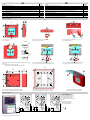
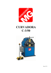
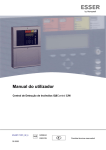
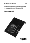
Manual de Instalación
Pulsador Manual Compacto Convencional
Installation Instruction
Electronic module / Conventional MCP
(Ref. / Part No. 804950 / 804970)
798935
03.2006
Cambios técnicos reservados!
GB
Technical changes reserved!
E
GB
Importante!
Se declina toda responsabilidad sobre daños derivados y garantía por
no seguir estas instrucciones de instalación. Estas instrucciones
deben ser tenidas en cuenta cuidadosamente antes de proceder a la
puesta en marcha del módulo electrónico / Pulsador Manual de
Alarma.
Información de seguridad
• NUNCA conecte el pulsador directamente a 220V ac
• Instale el pulsador dentro el rango de temperatura especificado.
• Solo técnicos cualificados que estén familiarizados con los
riesgos específicos y las normativas correspondientes deben
llevar a cabo las operaciones de reparación y mantenimiento del
Pulsador.
• El pulsador no debe ser alterado ni modificado.
Important!
Any damage caused by failure to observe the installation instructions
voids the product guarantee. Furthermore, no liability can be accepted
for any consequential damage arising from such failure. These
instructions must be studied carefully before commissioning the
conventional Electronic module / Manual Call Point (MCP).
General
El pulsador electrónico (Ref. 804950) ) o el pulsador manual (Ref.
804970) con carcasa roja está identificado con un símbolo de una
“casa ardiendo” para activación manual de sistemas de alarma u otros
sistemas en espacios secos no sujetos a riesgos de explosión. El
pulsador también está disponible en otras versiones para otras
aplicaciones, por ejemplo en carcasas de diferentes colores y con
elección de diferentes colores o etiqueta de identificación (ver tabla página 2).
Funccionamiento
Activar Alarma:
Revise ésta información!
Presione el cristal hacia adentro hasta que
aparezca la lengüeta amarilla (G) en la zona
superior de la ventana y el LED Rojo (F)
parpadee (Fig. 4).
Suba la cubierta de llave (A) e inserte la llave (Fig. 1)..
Rearme
Pulsador con Cristal
Abra la caja y retire el cristal. Gire la llave (C) en
sentido horario hasta el tope derecho (L) (Fig. 5).
Abra la cubierta y reemplace el cristal, gire la llave
en sentido contrahorario hasta el tope izquierdo (M)
para subir la lámina (Fig. 6).
Safety information
• NEVER connect the MCP directly to a 230V AC mains power
supply.
• Only operate in the specified ambient temperature range.
• Only qualified technicians who are fully familiar with all the
associated hazards and the applicable legislation and regulations
may perform maintenance and repair work on the call point.
• The call point may not be changed or modified in any way.
General
The conventional Electronic module (Part No. 804950) or Manual Call
Point (Part No. 804970) in the red housing identified with a “burning
house” symbol is designated for use as a call point for manually
triggering fire alarms or other hazard alarms in dry workplaces not
subject to explosion hazards. The call point is also available in other
versions for other applications, for example in housings with different
colours and with a choice of different identification labels (refer to
table - page 2)
Operation
Trigger alarm:
Push up the keyhole cover (A) to insert the key (Fig. 1).
Reset:
Novar GmbH a Honeywell Company
Instalación
Montaje
empotrado:
Dieselstraße 2, D-41469 Neuss
Montaje en
Superficie:
Internet: www.novar.de
E-Mail: [email protected]
Apertura:
Cuando se usa un Pulsador como pulsador de Alarma, se
debe usar una carcasa roja con una etiqueta de
identificación con el símbolo correcto como es mostrado en
Fig. 3 y 4.
Cuando se usan diferentes carcasas o diferentes símbolos,
el equipo está clasificado como equipo de activación y no
como Pulsador de Alarma
Observe la secuencia correcta del cableado:
Terminales 1-4: 1 (- Entrada), 2 (- Salida), 3 y 4 (+Común)
Use cable de comunicaciones claramente identificado
I-Y (St) Y n x 2 x 0.8 mm o cable para alarma de incendio!
La conexión de la malla del cable debe realizarse al
Terminal de tierra para evitar interferencias.
Se debe tener en cuenta durante el mantenimiento o
labores de reparación la activación de sistemas de aviso
como por ejemplo activación a central receptora.
Cierre:
Símbolo:
Etiqueta:
GB
When the MCP is used as a manual call point it must be
installed in a red housing with an identification label
showing the standardize-conformal symbol as shown in Fig.
3/4. When housings with different colours and identification
labels are used the unit is classed as a manual activation
device and not as a manual call point.
El pulsador puede instalarse sobre caja de
mecanismo estándar (Ø 55 – 60mm)
El pulsador se instala sobre caja de superficie
(opcional) o con marco de montaje universal
(opcional). Instale el Pulsador de un modo seguro,
en una pared apropiada sobre una superficie lisa,
con los tornillos y tacos adecuados. (Fig. 7/8).
Inserte la llave por sus dos patillas en los orificios
inferiores de la cubierta (abajo). Presione hacia
arriba para liberar la tapa (Fig. 2). Tire desde abajo
hacia fuera hasta retirar la tapa.
Gire la llave en sentido contrahorario hasta su tope
izquierdo (M) (Fig. 6). Coloque la lengüeta superior
de la cubierta sobre las ranuras del módulo del
pulsador y presione hasta encajar la cubierta en su
posición.
Abra la carcasa como se ha indicado y quite la
lámina transparente de plástico (D/E) presionando
hacia afuera, coloque el pictograma adecuado en el
frontal, coloque de nuevo la lámina transparente
sobre el nuevo pictograma y presione hasta su
posición (Fig. 3).
Para indicar equipo fuera de uso (J).
Lámina de
Gire la llave en sentido horario hasta el tope
plástico o cristal: derecho (L) (Fig. 5). Inserte la lámina o cristal en su
posición (H/K) en el hueco frontal deslice la lámina
hacia arriba girando la llave en sentido
contrahorario hasta su tope (M) (Fig. 6).
Terminales:
Los terminales 1-4 pueden extraerse para facilitar la
instalación (Fig. 10).
Use junta de paso para cableado para evitar el acceso de
humedad.
Siguiendo normas de instalación de VdS no es posible
configurar Pulsadores y Detectores en la misma zona de
Detección (max. 10 MCP por zona)
Si se usa el marco de montaje (Ref. 704967) deberá
montarse la cubierta blanca.
Gire la llave (C) en sentido horario hasta el tope
derecho (L) hasta que la lámina caiga y se indique
la activación (F/G) (Fig. 4). Para rearmar el equipo
gire la llave en sentido contrahorario hasta el tope
izquierdo (M), para subir la lámina.
Cubierta
Abatible:
Ref. 704965
(opcional)
La pantalla del cable debe interconectarse en
regleta separada. La caja de superficie tiene un
terminal apropiado para conectar la pantalla
(opcional) (Fig. 7).
Para proteger de activaciones no intencionadas y
para aumentar el grado de protección de IP 43 a IP
55. La cubierta abatible (N) se inserta en los
orificios laterales (O) de la carcasa y puede
precintarse en caso necesario (B) (Fig. 2/9).
Instalación típica (Fig. 10)
El pulsador convencional puede conectarse a la zona de incendios de
un panel convencional o a la entra de de un transponder esserbus® en
paneles 8000/IQ8Control de detección de incendio.
Conecte los cables de zona a los terminals 1-4 (Fig. 10). El ultimo
pulsador de la zona debe terminarse con la Resistencia de control de
línea, habitualmente 10KΩ en las zonas convencionales de equipos
de ESSER.
Observe the correct wiring sequence!
Terminals 1-4 (1 IN, 2 OUT, 3 u. 4 C)
Use designated communication cable
I-Y (St) Y n x 2 x 0.8 mm or fire alarm cable!
Connection of the cable shield to the ground terminal
protects the signal cables against interference.
The alarm activation and triggering of notifying systems
e.g. manned centre link (Master box) must be observed
during any Service of the MCP.
Install inlying cable with a dripping bend to protect the
device from dampness.
Pursuant to the VdS guidelines MCPs and automatic fire
detectors must not be operated in a common detector zone
(max. 10 MCP per detector zone).
By using the mounting frame (Part No. 704967) the white
covering must be fitted.
Características Técnicas
Alimentación
Tensión de funccionamiento
Consumo alarma
Número Pulsadores
Indicación alarma
Terminales
Temperatura trabajo
Temperatura almacenamiento
Grado de protección
Caja
Color
Peso
Dimensiones (a x h x f)
Diemnansiones c/ caja sup.
Especificación
Certificado VdS
:
:
:
:
:
:
:
:
:
:
:
:
:
:
:
:
:
8 V cc a 30 V cc
9 V cc
9 mA aprox. A 9Vcc
max. 10 por zona (VdS)
LED rojo / lámina amarilla
2,5 mm² máx. (AWG 26-14)
-20 °C a +70 °C
-30 °C a +75 °C
IP 43 (en carcasa)
IP 55 (con cubierta abatible)
Plástico PC/ASA
Rojo (similar RAL 3020)
110 g aprox.
88 x 88 x 21 (mm)
88 x 88 x 57 (mm)
EN 54-11, Typ A
G 205131
Detector with glass screen
Open housing and remove the broken glass. Turn
key (C) clockwise until the right (L) stop position
(Fig. 5). Replace glass screen and turn key (M)
anti-clockwise until the left stop position to lift
screen upwards (Fig. 6).
Pulsador con lámina rearmable
Gire la llave (C) en sentido horario hasta el tope
derecho (L) (Fig. 5). Coloque la lámina (K)
correctamente y gire la llave en sentido
contrahorario hasta el tope izquierdo (M) para subir
la lámina (Fig. 6).
Prueba:
Observe Info!
Press screen centre inwards until the yellow tab
indicator (G) is visible in the upper area and the red
LED (F) is flashing (Fig. 4).
Detector with plastic operating panel
Turn key (C) clockwise until the right (L) stop
position (Fig. 5). Align the plastic operating panel
(K) and turn key (M) anti-clockwise until the left stop
position to lift screen upwards (Fig. 6).
Test mode:
Installation
Flush mounting
Turn key (C) clockwise (L) until the screen moves
downwards and the activation (F/G) is indicated
(Fig. 4). To reset the detector after a test simply
turn key (M) to the left stop position to lift screen
upwards.
The Manual Call Point is installed on a conventional
standard housing (Ø 55 – 60mm).
Surface
mounting
The Manual Call Point is installed on a back box for
surface mounting (option) or with an universal
installation frame for wall mounting (option). The
call point securely on a suitable wall with a smooth
surface, e.g. with 2 screws (length ≥ 40mm) and
dowels (S6) (Fig. 7/8).
Opening:
Insert the key with the both tenons in the opening at
the bottom of the housing (Fig. 2) to release the
cover lock. Lift up the bottom edge of the cover a
little to release it and then remove it.
Closing:
Turn key lock anti-clockwise until the left (M) stop
position (Fig. 6). Position the upper edge of the
cover in the groove at the top of the base and then
press the cover down until it locks into position.
Symbolism:
Open the housing and remove the transparent
plastic cover (D/E) by prising it out. Insert the
appropriate identification label from the front. Align
the cover and snap it back into place (Fig. 3).
Paper inlay:
To indicate that the detector is out of order (J)
Plastic operating Turn key lock clockwise until the right (L) stop
panel or
position (Fig. 5). Insert screen (H/K) aligned in the
glass screen:
front recess und move screen upwards by turning
the key anti-clockwise until the left (M) stop position
(Fig. 6).
Terminals:
The screw terminals 1-4 can be removed to simplify
the installation (Fig. 10).
The cable shield of the connection cable must be
interconnected by using a single terminal block. The
back box (option) provides an integrated screw
terminal for the shield connection (Fig. 7).
Hinged cover:
Part No. 704965
(Option)
To protect the detector for unintended activation
and to increase the protection rating from IP 43 up
to IP 55.The hinged cover (N) is fixed by the
sideway dents (O) of the housing and may be
plumbed (B) if required (Fig.2/9).
Typical wiring (Fig. 10)
The MCP can be connected to a conventional detector zone of a fire
alarm control panel or to the zone input of an esserbus® transponder
in a System 8000 or IQ8Control fire alarm control panel.
Connect the signal cable to terminals 1-4 (Fig. 10). The last call point
in the zone must be fitted with a terminating resistor. This should be a
10KΩ resistor for all Esser conventional detector zones.
Specification
Power supply range
Operation voltage
Alarm current
MCP per zone
Alarm indicator
Connection terminals
Application temperature
Storage temperature
Protection rating
Housing
Colour
Weight
Housing dimensions (w x h x d)
Dimensions with back box
Call point specification
VdS approval
:
:
:
:
:
:
:
:
:
:
:
:
:
:
:
:
:
8 V DC to 30 V DC
9 V DC
approx. 9 mA @ 9 V DC
max. 10 MCP (acc. to VdS)
red LED and yellow tab
max. 2.5mm² (AWG 26-14)
-20 °C to +70 °C
-30 °C to +75 °C
IP 43 (in housing)
IP 55 (with hinged cover)
PC/ASA plastic
red (similar RAL 3020)
approx. 110 g
88 x 88 x 21 (mm)
88 x 88 x 57 (mm)
EN 54-11, type A
G 205131
E
GB
Opción
Ref.
Options
Part No.
Carcasa Azul similar RAL 5015
704951
Housing for MCP, blue similar to RAL 5015
704951
Cristal de repuesto (10 Uds.)
704960
Replacement glass screen (10 pieces)
704960
Etiqueta transparente para impresión de otros iconos (10 Uds.)
704961
Label, transparent with whit printing, differing from standard icons (10 pieces)
704961
Lámina de plástico rearmable (L) (10 Uds.)
704964
Plastic operating panel (K) resettable, white (10 pieces)
704964
Cubierta transparente abatible (O) para protección de activaciones no intencionadas y aumento de
grado de protección IP 43 a IP 55
704965
Hinged cover (N) to protect the detector for unintended activation and to increase
the protection rating from IP 43 up to IP 55
704965
Llave de repuesto (10 Uds.)
704966
Replacement key (10 pieces)
704966
Marco de monataje para pulsador compacto rojo + blanco (132 x 132 x 8 mm)
704967
Frame for small Manual Call Points incl. cover red + white (132 x 132 x 8 mm)
704967
Caja de montaje en superficie rojo similar RAL 3020
704980
Back box for surface mounting, red similar to RAL 3020
704980
Caja de montaje en superficie azul similar RAL 5015
704981
Back box for surface mounting, blue similar to RAL 5015
704981
Instalación / Mounting
21
D
15
88
88
B
E
C
A
Fig.1: Dimensiones
Fig. 1: Dimensions
Figura 2: Apertura de la tapa / carcasa
Fig. 2: Open the housing / seal
Figura 3: Etiqueta de identificación
Fig. 3: Identification label
Glasscheibe
Cristal/Glass
Glass screen
F
Oben
Arriba
Top
Top
G
J
Papiereinleger
Indicador
de Papel /
Paper inlay
inlay
Paper
Out of
Order
Außer
Betrieb
Oben
Arriba
Top
Top
K
704964 )
Kunststoffbedienfeld
(Art.-Nr.
Lámina rearmable
Ref.704964
Plastic
panel
(PartPart.Nº
No.704964)
Plasticoperating
operating
panel
704964
Arriba
Oben
Top
Top
L
M
L
Figura 4: Indicacidores LED y cubiertas de Plástico rearmable, cristal y papel
fuera de uso
Fig. 4: Mechanical alarm indicator and LED,
Glass screen, paper inlay and plastic operating panel
Figura 5: Posición de llave para prueba / extraer cristal
Fig. 5: Key lock position for test mode and removing screen
Figura. 6: Posición de llave para rearme / insertar cristal
Fig. 6: Key lock position for Reset / Replace screen
132
36
88
O
N
THIS WAY UP
88
50
132
18,5
44
Figura 7: Caja de montaje en superficie (Ref. 704980)
Fig. 7: Back box for surface mounting (Part No. 704980)
Figura 8: Marco de montaje universal (Art.-Nr. 704967)
Fig. 8: Universal installation incl. cover (Part No. 704967)
Figura 9: Cubierta abatible (Ref. 704965)
Fig. 9: Hinged cover (Part No. 704965)
8
7
6
5
C4
3
OUT 2
IN 1
8
7
6
5
C4
3
OUT 2
IN 1
8
7
6
5
C4
3
OUT 2
IN 1
System 8000 / IQ8Control
Nächster Melder oder
Siguiente equipo o final
Abschlusswiderstand
(R)de línea
EOL (resistencia).
Revise la
(Erforderlicher
Widerstandswert
documentación
de la central
o
siehe
Dokumentantion
der Zentrale)
equipo al que conecte el
pulsador para el valor del final de
línea
Next detector or
End-Of-Line resistor (R).
(Refer to Panels manual
for required resistance)
Meldergruppe /
Detector zone
MG / Zone # +
MG / Zone # -
Fig. 10: Instalación en zona convencional
Fig. 10: Wiring of the conventional detector zone
+
-
R