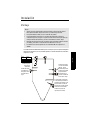
1
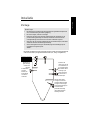
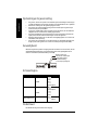
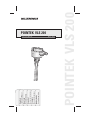
Instruction Manual
March 2002
POINTEK VLS 200
Gebruiksaanwijzing
Nederlands
Manuel d’Instructions
Français
Manual de Instrucciones
Español
Betriebsanleitung
Deutsch
Instruction Manual
English
POINTEK VLS 200
Safety Guidelines
Warning notices must be observed to ensure personal safety as well as that of others, and to
protect the product and the connected equipment. These warning notices are accompanied
by a clarification of the level of caution to be observed.
Qualified Personnel
This device/system may only be set up and operated in conjunction with this manual.
Qualified personnel are only authorized to install and operate this equipment in accordance
with established safety practices and standards.
Warning: This product can only function properly and safely if it is correctly transported,
stored, installed, set up, operated, and maintained.
Note: Always use product in accordance with specifications.
Copyright Siemens Milltronics Process
Instruments Inc. 2002. All Rights Reserved
Disclaimer of Liability
This document is available in bound version and in
electronic version. We encourage users to
purchase authorized bound manuals, or to view
electronic versions as designed and authored by
Siemens Milltronics Process Instruments Inc.
Siemens Milltronics Process Instruments Inc. will
not be responsible for the contents of partial or
whole reproductions of either bound or electronic
versions.
While we have verified the contents of
this manual for agreement with the
instrumentation described, variations
remain possible. Thus we cannot
guarantee full agreement. The
contents of this manual are regularly
reviewed and corrections are included
in subsequent editions. We welcome
all suggestions for improvement.
Technical data subject to change.
MILLTRONICS®is a registered trademark of Siemens Milltronics Process Instruments Inc.
Contact SMPI Technical Publications at the following address:
Technical Publications
Siemens Milltronics Process Instruments Inc.
1954 Technology Drive, P.O. Box 4225
Peterborough, Ontario, Canada, K9J 7B1
Email: [email protected]
For the library of SMPI instruction manuals, visit our Web site: www.milltronics.com
© Siemens Milltronics Process Instruments Inc. 2002
VLS 200 Introduction
The Pointek VLS 200 is a vibrating level switch that detects high or low levels of dry bulk
solids in bins, silos, or hoppers. The VLS 200 provides a contact output for levels of
products such as lime, styrofoam, flour, and plastic granules. With a compact design, the
VLS 200 can be top- or side-mounted. The vibrating fork design of the VLS 200 provides
constant self-cleaning to the tines.
Product Features
•
•
•
•
•
High resistance to mechanical forces
Strong vibration resistance to high bulk material loads
Rotatable enclosure
Stainless steel 1½” NPT or R 1½" DIN 2999 (tapered) threaded connection
Suitable for low density material (20 g/l or 1.2 lb/ft3)
Product Applications
•
•
Lime, styrofoam, flour, plastic granules
Low or high bulk density materials
Principle of Operation
A signal from the electronic circuit excites a crystal in the probe causing the fork to
vibrate at a frequency of 125 Hz. If the fork is covered by material, the change in vibration
is detected by electronic circuitry which causes the relay to change state after a one
second delay. When the material no longer reaches the tines, full vibration resumes and
the relay reverts to its normal condition.
7ML19981FT61
Pointek VLS 200 – INSTRUCTION MANUAL
Page 1
mmmmm
•
Installation, maintenance and commissioning must be performed by qualified
technical personnel.
The VLS 200 must be used only in the manner outlined in this instruction manual.
English
Notes
•
English
mmmmm
Specifications
Note: Siemens Milltronics makes every attempt to ensure the accuracy of these
specifications but reserves the right to change them at any time. Please ensure these
are the most recent specifications.
Check our web site at www.siemens-milltronics.com or contact your representative
for the most up-to-date information.
Power
• 19 to 230 Vac, +10%, 50 to 60 Hz, 8VA
• 19 to 55 Vdc, +10%, 1.5W
Alarm Output
• relay delay
– approx. 1 second from loss of vibration
– 1 to 2 seconds from resumption of vibration
• relay failsafe: high or low, switch selectable
• relay 8A at 250 Vac, non-inductive
relay 5A at 30 Vdc, non-inductive
Mechanical
Enclosure material
• epoxy coated aluminum
Process Connection
• thread 1½” NPT, R 1½” DIN 2999 (tapered)
• tine material: stainless steel 316Ti (1.4571)
• thread material: stainless steel 303 (1.4305)
Conduit entry
• 2 x M20 x 1.5
• 2 x ½” NPT
Weight
• approx. 1.9 kg, + 2.5 kg/m extension tube
Signal Delay
• probe free to covered: approx. 1 sec
• probe covered to free: approx 1 to 2 sec
Page 2
Pointek VLS 200– INSTRUCTION MANUAL
7ML19981FT61
Environmental
Location
Ingress Protection
• Type 4 / NEMA 4 / IP65
Ambient Temperature
• -25 to 60°C (-13 to 176°F)
Humidity
• 0 to 100%
Altitude
• max. 2000 m
Installation Category
• III
Pollution degree
• 2
Process
Temperature
• -20 to 80°C (-4 to 176°F)
• temperature code: T4A (CSA relevant)
• maximum surface temperature of the housing (Category 2D): 90ºC (194ºF) [ATEX
relevant]
Pressure
• max 0.5 bar (7 psi)
Note: The device construction allows over-pressure between -0.2 and 0.1 bar in
hazardous areas, and 0.5 bar in other applications for testing purposes only.
7ML19981FT61
Pointek VLS 200 – INSTRUCTION MANUAL
Page 3
mmmmm
English
• indoor/ outdoor
Sensitivity
English
mmmmm
• high or low, switch selectable
Minimum material density
• approx. 20 g/l (1.2 lb/ft3)
Measuring frequency
• approx. 125 Hz
Approvals
• FM/cCSA Class II, Div. 1, Group E, F, G, Class III
• CSAus Class II Div. 2, Class III
• ATEX II 1/2 D (dust explosion)
• CE
(see product nameplate for approval details)
Page 4
Pointek VLS 200– INSTRUCTION MANUAL
7ML19981FT61
Installation
Notes
•
•
•
•
•
Installation shall be performed by qualified personnel and in accordance with
local governing regulations.
Do not bend, shorten or extend the tines.
Position the tines using a 50 mm open-end wrench when installing the process
connection (do not turn the housing). Position the tines so the tine orientation
marking is vertical facing top or bottom.
After mounting, ensure the cable entries point downward to prevent water
ingress into the housing.
For VLS 200 extended model, the torque at the mounting point may not exceed
300 Nm.
The Pointek VLS 200 is normally mounted into the vessel top (full detector) or through the
tank wall at the detection level (full, demand or empty detector).
*
max. deviation max. length "L"
5º
4m
45º
1.2 m
>45º
0.6 m
*
"L"
protection in case
of high mechanical
loading
Position tines using a
50 mm open-end
wrench to turn the
process connection
so the tine
orientation marking
is vertical facing, top
or bottom.
cable gland
faces downward
to avoid water
intrusion
Only use angle mounting for
flowing material. If angle
mounting is required with
high mechanical loading,
customer supplied
protection from falling
material must be in place.
7ML19981FT61
Pointek VLS 200 – INSTRUCTION MANUAL
Page 5
mmmmm
English
Mounting
Process Cautions
Caution: Protect shaft and
tines from falling material.
English
mmmmm
Caution: Keep VLS 200 out of
path of falling material.
Dimensions
A
tine
orientation
marking
optional
process
flange
120 mm
(4.72")
VIEW A-A
A
60 mm 75 mm
(2.36") (2.95")
150 mm
(5.91")
Zone 21
(Cat. 2)
Zone 20
(Cat. 1)
60 mm
(2.36")
230 mm (9.0") compact version
300 to 4000 mm (11.81 to 157")
customer specified rigid extension
170 mm
(6.69")
Page 6
Pointek VLS 200– INSTRUCTION MANUAL
7ML19981FT61
Wiring
•
•
All field wiring must have insulation suitable for at least 250 Vac.
A disconnect switch must be in close proximity to the equipment and within easy
reach of the operator.
• Use appropriate conduit or cable glands in hazardous locations. Unused cable
conduit fittings must be locked with a closing element or plug.
• Observe all pertinent rules and regulations in the country of installation.
European requirements
• When mounting the VLS 200 in hazardous areas, make sure the customer
supplied cable glands and/or plugs are certified ATEX 100a flameproof. The
certified temperature range must be at least -25 to 70°C (-13 to 158°F). The
minimum ingress protection requirement of IP6x according to European Standard
EN 60529 must be satisfied. Observe special conditions for safe use of the cable
gland described in the gland’s approval documentation.
• The requirements of European Standard EN 50281-1-2 regarding dust deposits
and temperature must be followed.
Connection
FSH/FSL adjustment
FSL
B
sensitivity adjustment
(B=factory setting,
A=decreased sensitivity)
NC
FSH
A
NO
1
2
3
4
5
protective earth terminal
alarm output relay
AC:
terminal 1: L
terminal 2: N
19 to 230 Vac, +10%, 50 to 60 Hz, 8VA or
DC:
terminal 1: +
terminal 2: 19 to 55 Vdc, +10%, 1.5W
7ML19981FT61
Pointek VLS 200 – INSTRUCTION MANUAL
Page 7
mmmmm
English
Open VLS 200 only when supply voltage is switched off.
Connection Notes
English
mmmmm
•
•
•
•
•
•
•
Before opening the lid, ensure there are no dust deposits around the VLS 200.
Ensure that the atmosphere around the VLS 200 is settled.
Use a fuse for the signal output (max. 10A).
Make sure the main voltage does not exceed the maximum voltage listed on the
product label.
In case of inexpert handling or handling malpractice, the electrical safety of the
device cannot be guaranteed.
Provide protection for relay contacts to protect the device against spikes if inductive
loads are connected.
Ensure that a maximum of 8 mm of the pigtails are bared (danger of contact with
live parts.)
Ensure the boots for protecting cable terminations are not longer than 8 mm (danger
of contact with live parts.)
Sensitivity
If the measured material tends to cake or deposit, the sensitivity adjustment switch can
be set to position A to decrease the sensitivity of the probe (factory setting is position B).
FSH/FLS adjustment (see Switching
Logic below)
sensitivity adjustment (B=factory
setting, A=decreased sensitivity)
Switching Logic
Setting
Failsafe High
Probe
free
Relay output
3 4 5
actuated
covered
3 4 5
idle
Failsafe Low
free
3 4 5
idle
covered
3 4 5
actuated
Power Failure
free or covered
3 4 5
idle
Maintenance
The VLS 200 requires no maintenance or cleaning.
Page 8
Pointek VLS 200– INSTRUCTION MANUAL
7ML19981FT61
VLS 200: Einleitung
Hinweise:
•
•
Installation, Wartung und Inbetriebnahme müssen durch qualifiziertes,
technisches Personal vorgenommen werden.
Der VLS 200 darf nur gemäß den Anweisungen in dieser Betriebsanleitung
verwendet werden.
•
•
•
•
•
Hohe mechanische Beständigkeit
Starke Vibration, auch für starke Belastungen geeignet
Verdrehbares Gehäuse
Gewindeanschluss aus Edelstahl 1½” NPT oder R 1½" DIN 2999 (konisch)
Für leichtes Material geeignet (20 g/l oder 1.2 lb/ft3)
Applikationen des Produkts
•
•
Kalk, Styropor, Mehl, Kunststoffgranulat
Materialien mit hoher oder geringer Dichte
Funktionsweise
Die Schwingsonde schwingt piezo-elektrisch angeregt auf ihrer mechanischen
Resonanzfrequenz von ca. 125 Hz. Wird die Sonde durch das Füllgut bedeckt, so wird die
dadurch entstehende Dämpfung elektronisch registriert und ein entsprechender
Schaltausgang nach einer Sekunde Ansprechverzögerung betätigt. Sobald die
Schwingsonde frei vom Materialdruck ist, nimmt die Schwingung wieder auf und das
Relais kehrt in seinen normalen Zustand zurück.
7ML19981FT61
Pointek VLS 200 – BETRIEBSANLEITUNG
Seite 1
mmmmm
Merkmale des Produkts
Deutsch
Der Vibrations-Füllstand-Grenzstandschalter Pointek VLS 200 erfasst die An- oder
Abwesenheit rieselfähiger Schüttgüter in Behältern, Silos oder Trichtern. Der VLS 200
liefert einen Signalausgang zur Anzeige eines Min- oder Max-Alarms. Unterschiedliche
Produkte können gemessen werden, wie z. B. Kalk, Styropor, Mehl und Kunststoffgranulat. Der VLS 200 hat ein kompaktes Design und kann senkrecht oder seitlich
eingebaut werden. Die Vibration der Schwingschenkel bewirkt eine Selbstreinigung des
Gerätes.
Technische Daten
Hinweis: Siemens Milltronics ist bestrebt, die Genauigkeit der technischen Daten zu
gewährleisten, behält sich jedoch das Recht auf jederzeitige Änderungen vor. Bitte
prüfen Sie, dass es sich hierbei um die aktuellsten Daten handelt.
Wenden Sie sich an Ihren Vertreter oder vergleichen Sie mit den aktuellsten Daten
auf unserer Webseite: www.siemens-milltronics.com.
Deutsch
mmmmm
Hilfsenergie
• 19 bis 230 VAC, +10%, 50 bis 60 Hz, 8VA
• 19 bis 55 VDC, +10%, 1.5W
Alarmausgang
• Relais Ansprechverzögerung
– ca. 1 Sekunde ab Unterbrechung der Vibration
– 1 bis 2 Sekunden ab Wiederaufnahme der Vibration
• Relaisfailsafe: Min. oder Max, über Schalter wählbar
• Relais 8A bei 250 VAC, ohmsche Last
Relais 5A bei 30 VDC, ohmsche Last
Mechanische Daten
Gehäusematerial
• Aluminium mit Epoxidbeschichtung
Prozessanschluss
• 1½” NPT, R 1½” DIN 2999 (konisch) Gewinde
• Material der Schwinger: Edelstahl 1.4571 (316Ti)
• Gewindematerial: Edelstahl 1.4305 (303)
Kabeleinführung
• 2 x M20 x 1.5
• 2 x ½” NPT
Gewicht
• ca. 1.9 kg, + 2.5 kg/m Verlängerungsrohr
Signalverzögerung
• Sonde frei -> bedeckt: ca. 1 Sekunde
• Sonde bedeckt -> frei: ca. 1 bis 2 Sekunde(n)
Seite 2
Pointek VLS 200– BETRIEBSANLEITUNG
7ML19981FT61
Umgebung
Montage
• innen / im Freien
Schutzart
• Typ 4 / NEMA 4 / IP65
Umgebungstemperatur
• -25 bis 60°C (-13 bis 176°F)
Feuchtigkeit
Höhe
• max. 2000 m
Installationskategorie
• III
Verschmutzungsgrad
• 2
Prozess
Temperatur
• -20 bis 80°C (-4 bis 176°F)
• Temperaturcode: T4A (nach CSA)
• Maximale Oberflächentemperatur des Gehäuses (Kategorie 2D): 90ºC (194ºF) (nach
ATEX)
Druck
• max 0.5 bar (7 psi)
Hinweis: Die Gerätebauweise erträgt einen Überdruck von bis -0,2 zu 0.1 bar in
explosionsgefährdeten Bereichen und 0,5 bar in anderen Applikationen
(ausschließlich zu Testzwecken).
7ML19981FT61
Pointek VLS 200 – BETRIEBSANLEITUNG
Seite 3
mmmmm
Deutsch
• 0 bis 100%
Empfindlichkeit
• Min. oder Max., einstellbar
Min. Schüttgewicht
• ca. 20 g/l (1.2 lb/ft3)
Messfrequenz
• ca. 125 Hz
Deutsch
mmmmm
Zulassungen
• FM/cCSA Klasse II, Div. 1, Gruppen E, F, G, Klasse III
• CSAus Klasse II, Div. 2, Klasse III
• ATEX II 1/2 D (Staubexplosion)
• CE
(Nähere Angaben zu den Zulassungen finden Sie auf dem Typenschild)
Seite 4
Pointek VLS 200– BETRIEBSANLEITUNG
7ML19981FT61
Installation
Montage
Hinweise
•
•
•
Der VLS 200 wird üblicherweise von oben (als Vollmelder) oder seitlich in Höhe des zu
erfassenden Füllstandes (Voll-, Leer- oder Bedarfsmelder) in den Behälter eingeschraubt.
*
max. Abweichung
5º
45º
>45º
max. Länge "L"
4m
1.2 m
0.6 m
*
"L"
Schwingstäbe mit
Gabelschlüssel 50
mm vertikal
ausrichten:
Prozessanschluss
drehen, bis die
Orientierungsmarke
nach oben oder
unten zeigt.
Stahlwinkel bei
hoher mech.
Belastung
Kabelverschraubung zeigt nach
unten zur
Vermeidung von
Wassereintritt
Ein schräger Einbau
empfiehlt sich nur bei
rieselfähigem Schüttgut.
Bei einer starken
mechanischen Belastung
wird in diesem Fall ein
kundenseitiger
Stahlwinkel zum Schutz
vor herabfallendem
Material empfohlen.
7ML19981FT61
Pointek VLS 200 – BETRIEBSANLEITUNG
Seite 5
mmmmm
•
Deutsch
•
Die Installation darf nur durch qualifiziertes Personal und unter Beachtung der
örtlichen Bestimmungen durchgeführt werden.
Die Schwingstäbe nicht verbiegen oder kürzen oder verlängern.
Richten Sie die Schwingstäbe bei der Installation des Prozessanschlusses mit
einem Gabelschlüssel 50 mm aus (nicht am Gehäuse drehen). Die Schwingstäbe
sind vertikal auszurichten, so dass die Orientierungsmarke nach oben oder unten
zeigt.
Nach der Montage ist zu prüfen, dass die Kabeleinführungen zur Vermeidung von
Wassereintritt nach unten gerichtet sind.
Für die VLS 200 Ausführung mit Verlängerung darf das Drehmoment maximal
300 Nm betragen.
Prozessbedingungen
Vorsicht: Schützen Sie die
Welle und die Schwingstäbe
vor herabfallendem Material.
Deutsch
mmmmm
Vorsicht: Den VLS 200 nicht unterhalb der Befüllung anbringen.
Abmessungen
A
Orientierungsmarke für
Schwingstäbe
optionaler
Prozessflansch
120 mm
(4.72")
Ansicht
A-A
VIEW A-A
A
60 mm 75 mm
(2.36") (2.95")
150 mm
(5.91")
Zone 21
(Kat. 2)
Zone 20
(Kat. 1)
60 mm
(2.36")
230 mm (9.0") kompakte Ausführung
300 bis 4000 mm (11.81 to 157")
Rohrverlängerung nach Kundenmaß
170 mm
(6.69")
Seite 6
Pointek VLS 200– BETRIEBSANLEITUNG
7ML19981FT61
Anschluss
Vor dem Öffnen des VLS 200 ist die Stromversorgung auszuschalten.
•
•
FSL
B
Einstellschalter FSH/FSL
NC
Einstellschalter für
Empfindlichkeit
(B=Werkseinstellung,
A=verminderte
Empfindlichkeit)
FSH
A
NO
1
2
3
4
5
Erdungsanschluss
Alarmausgangsrelais
AC:
Klemme 1: L / Klemme 2: N
19 bis 230 VAC, +10%, 50 bis 60 Hz, 8VA oder
DC:
Klemme 1: + / Klemme 2: 19 bis 55 VDC, +10%, 1.5W
7ML19981FT61
Pointek VLS 200 – BETRIEBSANLEITUNG
Seite 7
mmmmm
Anschluss
Deutsch
Alle Feldanschlüsse müssen mind. gegen 250 VAC isoliert sein.
Ein Schalter als Trennvorrichtung für die Anschluss-Spannung muss in der Nähe
des Gerätes und für den Bediener leicht erreichbar angebracht sein.
• In Ex-Bereichen sind geeignete Kabeleinführungen zu verwenden. Unbenutzte
Anschluss-Stücke des Kabelschutzrohrs müssen auf geeignete Weise
verschlossen oder verstopft werden.
• Beachten Sie alle einschlägigen Regeln und Richtlinien des Installationslandes.
Europäische Normen
• Bei der Montage des VLS 200 in Ex-Bereichen muss sichergestellt sein, dass die
kundenseitigen Kabelverschraubungen und/oder Stopfen nach ATEX 100a
druckfest zugelassen sind. Der zugelassene Temperaturbereich liegt bei -25 bis
70°C (-13 bis158°F). Die minimale Schutzart IP6x muss die Europäische Norm EN
60529 erfüllen. Für den sicheren Einsatz der Kabeleinführungen sind die in der
zugehörigen Dokumentation beschriebenen Sonderbedingungen zu beachten.
• Die Anforderungeen der Europäischen Norm EN 50281-1-2 bezüglich
Staubablagerungen und Temperaturen müssen erfüllt werden.
Anmerkungen zum Anschluss
•
•
•
•
•
•
Deutsch
mmmmm
•
Vor dem Öffnen des Deckels vergewissern Sie sich, dass sich um das VLS 200 keine
Staubablagerungen gebildet haben. Die Umgebungsatmosphäre des VLS 200 muss
sich beruhigt haben.
Verwenden Sie eine Sicherung für den Signalausgang (max. 10A).
Die Netzspannung darf die auf dem Typenschild angegebene maximale Spannung
und die am Gerät gewählte Spannung nicht überschreiten.
Bei unsachgemäßem Gebrauch des Gerätes ist die elektrische Sicherheit nicht
gewährleistet.
Zum Schutz vor Spannungsspitzen bei induktiven Lasten einen Schutz für
Relaiskontakte vorsehen.
Achten Sie darauf, dass die Anschlusslitzen max. 8 mm abisoliert sind (Gefahr der
Berührung spannungsführender Teile.)
Achten Sie darauf, dass die Schutzteile der Kabelendverschlüsse nicht länger als
8 mm sind (Gefahr der Berührung spannungsführender Teile.)
Empfindlichkeit
Wenn das zu messende Material zur Ansatzbildung neigt, kann der Einstellschalter für
die Empfindlichkeit auf A eingestellt werden. Damit wird die Empfindlichkeit der Sonde
vermindert (Werkseinstellung ist B).
Einstellung FSH/FLS (siehe
Schaltlogik unten)
Einstellung Empfindlichkeit
(B=Werkseinstellung,
A=verminderte Empfindlichkeit)
Schaltlogik
Einstellung
Max. Sicherheit
FSH
Sonde
frei
Relaisausgang
3 4 5
betätigt
bedeckt
3 4 5
stromlos
Min. Sicherheit
FSL
frei
3 4 5
stromlos
bedeckt
3 4 5
betätigt
Stromausfall
frei oder bedeckt
3 4 5
stromlos
Wartung
Der VLS 200 erfordert weder Wartung noch Reinigung.
Seite 8
Pointek VLS 200– BETRIEBSANLEITUNG
7ML19981FT61
Sensor VLS 200
Notas
•
•
Sólo el personal calificado debe intervenir durante la instalación y la puesta en
marcha del sistema.
Es imprescindible utilizar el dispositivo VLS 200 respetando las instrucciones
proporcionadas en este manual de instrucciones.
El Pointek VLS 200 es un sensor de horquilla vibrante. Este dispositivo detecta la
presencia o ausencia de sólidos secos a granel en bins, silos o tolvas. El VLS 200
proporciona una salida de contacto que indica una alarma de alto o bajo nivel. Es idóneo
para monitorizar productos como cal, espuma de poliestireno, harina y gránulos de
plástico. Su diseño modular y compacto permite la instalación en la parte superior o
lateral del depósito. La forma de la horquilla y la acción de la vibración permiten la
limpieza automática del VLS 200.
Características del producto
Aplicaciones del producto
•
•
Cal, espuma de poliestireno, harina y gránulos de plástico
Detecta materiales ligeros o pesados
Principio de funcionamiento
Una señal proveniente del circuito electrónico excita un cristal en la sonda, provocando
la vibración de la horquilla con una frecuencia de resonancia de 125 Hz. Cuando el
material entra en contacto con la horquilla de la sonda se detiene la vibración. Esta
variación es detectada por el circuito electrónico que provoca que el relé cambie de
estado después de un segundo. Cuando se descubre la horquilla, se reanuda la vibración
y el relé vuelve a su condición normal.
7ML19981FT61
Pointek VLS 200 – MANUAL DE INSTRUCCIONES
Página 1
mmmmm
Alta resistencia a fuerzas mecánicas
Mecanismo de vibración para cargas importantes de sólidos
Caja orientable
Conexión roscada de acero inoxidable, 1½” NPT ó R 1½" DIN 2999 (cónico)
Detección de materiales ligeros (20 g/l ó 1.2 lb/pies3)
Español
•
•
•
•
•
Especificaciones técnicas
Nota: Siemens Milltronics hace todo lo necesario para garantizar la exactitud de las
especificaciones proporcionadas en el manual de instrucciones. Sin embargo, estas
informaciones quedan sujetas a cambios sin preaviso. Le recomendamos
encarecidamente que consulte las últimas especificaciones para beneficiarse de
todas las funciones del dispositivo. Para más detalles consulte www.siemensmilltronics.com o contacte nuestro representante.
Alimentación eléctrica
• 19 a 230 Vac, +10%, 50 a 60 Hz, 8VA
• 19 a 55 Vdc, +10%, 1.5W
Español
mmmmm
Salida de alarma
• Retardo de conmutación (relé)
– aproximadamente 1 segundo cuando se cubre la horquilla
– 1 a 2 segundos cuando se descubre la horquilla
• Autoprotección relé: alta o baja, ajuste por conmutador
• Relé: 8A a 250 VAC, no inductivo ó 5A a 30 VDC, no inductivo
Detalles mecánicos
Material del encapsulado
• Aluminio con revestimiento epoxi
Conexión del proceso
• Rosca 1½” NPT, R 1½” DIN 2999 (cónico)
• Material de la horquilla: acero inoxidable 316Ti (1.4571)
• Material de la rosca: acero inoxidable 303 (1.4305)
Entrada de cable
• 2 x M20 x 1.5
• 2 x ½” NPT
Peso (aproximativo)
• 1.9 kg, + 2.5 kg/m (tubo de ampliación)
Retardo (señal)
• horquilla descubierta > cubierta: 1 segundo aproximadamente
• horquilla cubierta > descubierta: 1 ó 2 segundos aproximadamente
Página 2
Pointek VLS 200– MANUAL DE INSTRUCCIONES
7ML19981FT61
Condiciones ambientales
Ubicación
• apto para interior / exterior
Indice de protección
• Tipo 4 / NEMA 4 / IP65
Temperatura ambiente
• -25 a +60°C (-13 a +176°F)
Humedad
• 0 a 100%
Altitud
• máximo 2000 m
Categoría de instalación
• III
Grado de contaminación
• 2
Temperatura
• -20 a +80°C (-4 a +176°F)
• Código de temperatura : T4A (CSA)
• La temperatura de superficie del encapsulado (Categoría 2D) no deberá exceder 90ºC
(194ºF) (ATEX)
Presión
• máximo 0.5 bar (7 psi)
Nota: El aparato puede ser utilizado con presiones de hasta entre -0.2 y 0.1 bar en
zonas peligrosas y 0.5 bar en otras aplicaciones (solo para pruebas y verificaciones).
7ML19981FT61
Pointek VLS 200 – MANUAL DE INSTRUCCIONES
Página 3
mmmmm
Español
Proceso
Sensibilidad
• alto o bajo, ajuste por conmutador
Mínima densidad del material
• 20 g/l (1.2 lb/pies3) aproximadamente
Frecuencia de medición
• 125 Hz aproximadamente
Aprobaciones
• FM/cCSA Clase II, Div. 1, Grupo E, F, G, Clase III
• CSAus Clase II, Div. 2, Clase III
Español
mmmmm
• ATEX II 1/2 D (explosión de polvos)
• CE
(para más detalles acerca de las aprobaciones, véase la placa indicadora)
Página 4
Pointek VLS 200– MANUAL DE INSTRUCCIONES
7ML19981FT61
Instalación
Montaje
Notas
•
•
•
•
•
Solo el personal calificado debe intervenir durante la instalación del sistema.
Dicho personal deberá respetar las normas y condiciones pertinentes.
Es imprescindible no doblar, acortar o extender las paletas.
La horquilla deberá orientarse con una llave abierta (50 mm) al instalar la
conexión del proceso, sin girar la caja de la sonda. Orientar la horquilla para que
esté posicionada verticalmente, y la marca orientada hacia arriba / abajo.
Después del montaje de la sonda, comprobar que la entrada de cables se efectúe
por debajo, para evitar la acumulación de condensación en la caja.
La máxima fuerza vertical posible en una sonda VLS 200 con ampliación es
300 Nm.
La sonda Pointek VLS 200 está diseñada para el montaje en la parte superior del depósito
(detección de nivel lleno) o en la pared del depósito, en el nivel de detección (nivel lleno,
específico o vacío).
*
*
"L"
Protección (para
altas cargas
mecánicas)
Orientar la horquilla
con una llave abierta
(50 mm) - girar la
conexión del proceso
hasta que la horquilla
esté posicionada
verticalmente y la
marca de orientación
hacia arriba / abajo.
Entrada de cables
orientada hacia
abajo para evitar
la infiltración de
agua.
El inclinado de la sonda solo
se recomienda para detectar
materiales poco densos. Si se
precisa inclinar la sonda en
aplicaciones con altas cargas
mecánicas se recomienda
instalar una protección
(provista por el cliente).
7ML19981FT61
Pointek VLS 200 – MANUAL DE INSTRUCCIONES
Página 5
mmmmm
Máxima
longitud "L"
4m
1.2 m
0.6 m
Español
Máxima
inclinación
5º
45º
>45º
Observaciones para la instalación
Precaución: Mantener el sensor VLS 200
lejos de la entrada (caida) de material.
Precaución: Protejer el eje y la
horquilla de la caida de material.
Español
mmmmm
Dimensiones
A
Marca para
la orientación
de la
horquilla
Brida de
proceso
(opcional)
120 mm
(4.72")
VIEW A-A
A
60 mm 75 mm
(2.36") (2.95")
150 mm
(5.91")
Zona 21
(Cat. 2)
Zona 20
(Cat. 1)
60 mm
(2.36")
Versión compacta: 230 mm (9.0’’)
Versión con ampliación rígida: 300 a 4000 mm (11.81 a 157"),
según las especificaciones del usuario
170 mm
(6.69")
Página 6
Pointek VLS 200– MANUAL DE INSTRUCCIONES
7ML19981FT61
Conexiones eléctricas
Antes de abrir el VLS 200 tiene que comprobarse que la
alimentación eléctrica esté desconectada.
•
•
Aislar todos los cableados (mínimo 250 VAC).
Deberá proveerse un interruptor de disconexión cerca del sistema, identificado y
fácilmente accesible.
• Utilizar prensaestopas para cables o conductos especiales para zonas
peligrosas, y tapones apropiados y certificados para cerrar los conductos
inutilizados.
• Deben observarse las normas y disposiciones pertinentes.
Estándares europeos
• Al instalar la sonda VLS 200 en una zona peligrosa se recomienda comprobar que
los prensaestopas y/o tapones proporcionados por el cliente cumplan la directiva
ATEX 100a (protección antiexplosión). No deberán sobrepasarse los límites de
temperatura (-25 a +70°C / -13 a +158°F) y deberá respetarse el índice de
protección mínimo (IP6x) de acuerdo con la norma europea EN 60529. Para la
utilización de los prensaestopas deben observarse las disposiciones pertinentes
y tomarse en cuenta las recomendaciones proporcionadas en la documentación.
• La sonda deberá utilizarse observando las condiciones de la norma EN 50281-1-2
(acumulaciones de polvo y temperaturas).
Ajuste FSH/FSL
FSL
B
Ajuste de la sensibilidad
B=ajuste de fábrica,
A=menor sensibilidad
NC
FSH
A
NO
1
2
3
4
5
Borne de conexión a
tierra (protección)
Relé salida alarma
AC:
Borne 1: L. Borne 2: N
19 a 230 VAC, +10%, 50 a 60 Hz, 8VA ó
DC:
Borne 1: +. Borne 2: 19 a 55 VDC, +10%, 1.5W
7ML19981FT61
Pointek VLS 200 – MANUAL DE INSTRUCCIONES
Página 7
mmmmm
Español
Conexiones
Notas para la conexión
•
Antes de abrir la tapa comprobar que el VLS 200 esté libre de acumulación de polvo
y esperar que le estabilice la atmósfera donde se ha instalado la sonda.
Proteger la salida de señal con un fusible (máximo 10A).
El voltaje no deberá exceder el máximo voltaje indicado en la etiqueta del producto.
Advertimos que si este aparato se manipula de manera inadecuada o incorrecta no
se podrá garantizar su seguridad eléctrica.
Al utilizar cargas inductivas es imprescindible proteger los contactos de relés para
proteger el sistema de picos.
Para evitar el contacto con componentes bajo tensión solo deberá descubrirse una
sección (8 mm) de los rabillos.
Para evitar el contacto con componentes bajo tensión proteger las terminaciones
de los cables con manguitos que no excedan 8 mm.
•
•
•
•
•
•
Ajuste de la sensibilidad
Si el producto detectado tiende a endurecerse o acumularse, el usuario puede disminuir
la sensibilidad del sensor ajustando el conmutador de selección en la posición A. Este
conmutador se ajusta en fábrica en la posición B.
Español
mmmmm
Ajuste FSH/FLS (véase ’Lógica de
conmutación’)
Ajuste de la sensibilidad
(B=ajuste de fábrica,
A=menor sensibilidad)
Lógica de conmutación
Ajuste
Autoprotección
alta (FSH)
Sonda
descubierta
Salida relé
3 4 5
activada
cubierta
3 4 5
desactivada
Autoprotección
baja (FSL)
descubierta
3 4 5
desactivada
cubierta
3 4 5
activada
Fallo de la
alimentación
eléctrica
descubierta o
cubierta
3 4 5
desactivada
Mantenimiento
El sensor VLS 200 no necesita limpieza ni mantenimiento.
Página 8
Pointek VLS 200– MANUAL DE INSTRUCCIONES
7ML19981FT61
Introduction au VLS 200
Remarques
•
•
L’installation, la maintenance et la mise en service de ce matériel doivent être
effectuées par un personnel possédant les qualifications nécessaires.
Le VLS 200 ne peut être utilisé que suivant les recommandations fournies dans la
présente notice d’utilisation.
Le Pointek VLS 200 est un dispositif électromécanique à lame vibrante utilisé pour
détecter la présence ou l’absence de solides dans les réservoirs, silos ou trémies. Le VLS
200 délivre une sortie alarme pour l’indication d’une alarme niveau haute ou basse et
peut être utilisée pour la détection de chaux, mousse de polystyrène, farine et granulés
plastique. Grâce à son design compact le VLS 200 peut être installé sur la partie
supérieure ou latérale du silo. L’oscillation des lames du VLS 200 permet l’auto-nettoyage
de la sonde.
Particularités du VLS 200
•
•
•
•
•
Très résistant aux forces mécaniques
Mécanisme de vibration adapté aux charges importantes (vrac)
Boîtier orientable
Raccord process 1½” NPT ou R 1½” DIN 2999 (conique), en acier inoxydable
Convient pour les solides légers (20 g/l ou 1.2 lb/pieds3)
Applications de VLS 200
•
•
Chaux, mousse de polystyrène, farine, granulés plastique
Convient aux applications avec des produits solides de densité variable
Principe de fonctionnement
Pointek VLS 200 – MANUEL D’INSTRUCTIONS
Page 1
mmmmm
7ML19981FT61
Français
La sonde à lames vibrantes possède un capteur piezoélectrique dont la fréquence de
résonance est 125 Hz. Lorsque la sonde est couverte par le produit, l’amortissement
provoqué est enregistré électroniquement, et actionne la mise en circuit. Le temps de
réaction est 1 seconde environ. Lorsque la pale est à nouveau libérée par la descente du
produit, la vibration reprend et le relais est mis au repos.
Caractéristiques techniques
Remarque : Siemens Milltronics vérifie les informations fournies dans ce document
pour garantir la conformité avec les caractéristiques du système. Cependant, nous
nous réservons le droit d’effectuer des modifications sans préavis. Il est donc
souhaitable de vérifier les spécifications fournies. Pour plus de détails consulter
notre site web www.siemens-milltronics.com ou contacter notre représentant.
Alimentation
• 19 à 230 VCA, +10%, 50 à 60 Hz, 8VA
• 19 à 55 Vcc, +10%, 1.5W
Contact d’alarme (sortie)
• Temps de réaction
– 1 seconde environ dès l’arrêt de la vibration
– 1 à 2 secondes dès la reprise de la vibration
• Sécurité-défaut relais: haut ou bas, sélection par commutateur
• Relais 8A - 250 VCA, non inductif
Relais 5A - 30 Vcc, non inductif
Détails mécaniques
Matériau (boîtier)
• Aluminium avec revêtement époxy
Français
mmmmm
Raccord process
• Filetage 1½” NPT, R 1½” DIN 2999 (conique)
• Lames : acier inoxydable 316Ti (1.4571)
• Filetage : acier inoxydable 303 (1.4305)
Entrée de câble
• 2 x M20 x 1.5
• 2 x ½” NPT
Poids
• 1.9 kg environ, + 2.5 kg/m avec tube prolongateur
Mise en circuit (signal)
• Sonde libre > couverte : 1 seconde environ
• Sonde couverte > libre : 1 à 2 secondes environ
Page 2
Pointek VLS 200– MANUEL D’INSTRUCTIONS
7ML19981FT61
Caractéristiques environnementales
Montage
• En intérieur / extérieur
Indice de protection
• IP65 / Type 4 / NEMA 4
Température ambiante
• -25 à +60°C (-13 à +176°F)
Humidité
• 0 à 100%
Altitude
• 2000 m maximum
Catégorie d’installation
• III
Degré de pollution
• 2
Process
Température
• -20 à +80°C (-4 à +176°F)
• Code de température : T4A (CSA)
• La température à la surface du boîtier (Catégorie 2D) ne doit pas dépasser : 90ºC
(194ºF) (ATEX)
• 0.5 bar (7 psi) maximum
Remarque : La construction du dispositif peut tolérer une pression entre -0.2 et 0.1
bars en zone dangereuse, et 0.5 bars dans les autres applications (à titre d’essai et
pour une courte période uniquement).
7ML19981FT61
Pointek VLS 200 – MANUEL D’INSTRUCTIONS
Page 3
mmmmm
Français
Pression
Sensibilité de réponse
• Haute ou basse, réglable par commutateur
Densité moyenne minimale du produit
• 20 g/l (1.2 lb/pieds3) environ
Fréquence de mesure
• 125 Hz environ
Homologations
• FM/cCSA Classe II, Div. 1, Groupe E, F, G, Classe III
• CSAus Classe II, Div. 2, Classe III
Français
mmmmm
• ATEX II 1/2 D (zones poussiéreuses explosibles)
• CE
(Pour plus de détails sur les homologations se référer à la plaque signalétique)
Page 4
Pointek VLS 200– MANUEL D’INSTRUCTIONS
7ML19981FT61
Installation
Montage
Remarques
•
•
•
•
•
L’installation doit être effectuée par un personnel qualifié, en accord avec les
dispositions locales en vigueur.
Ne pas plier, couper ou prolonger les raccords à visser.
Le raccord à visser doit être fixé avec une clé ouverte de 50 mm, lors de
l’installation du raccord process (sans tourner le boîtier). Orienter les fourches de
sorte que le point de repère soit dirigé vers le haut ou le bas.
Après le montage, tourner le boîtier de manière à ce que l’entrée de câble soit
dirigée vers le bas pour éviter les infiltrations d’eau.
Couple maximum au point de montage du VLS 200 (modèle avec prolongement) :
300 Nm.
Le montage du système Pointek VLS 200 peut être horizontal, sur le haut du réservoir
(détection de niveau plein) ou vertical, à travers la paroi du silo et au niveau de détection
(détection d’un niveau plein, spécifique ou vide).
*
Ecart max. Longueur "L" max.
5º
4m
45º
1.2 m
>45º
0.6 m
*
"L"
Protection (utilisée
lorsque la charge
mécanique est
importante
Presse étoupe
dirigé vers le bas
pour éviter les
infiltrations
7ML19981FT61
Pointek VLS 200 – MANUEL D’INSTRUCTIONS
Page 5
mmmmm
Incliner la sonde uniquement
si le produit détecté est en
libre écoulement. Si ce type
de montage est requis et la
charge mécanique est
importante, utiliser une
protection (fournie par le
client) pour abriter la sonde
des chutes de produit.
Français
Fixer les raccords à
visser avec une clé
ouverte 50 mm.
Orienter le raccord
process de sorte que
les lames soient
verticale et le repère
soit dirigé vers le
haut / bas).
Préconisations process
Avertissement : Ne pas installer le VLS
200 à proximité des chutes de matériau.
Avertissement : Protéger l’axe et
les lames des chutes de matériau.
Dimensions
A
Français
mmmmm
Repère pour
l’orientation
de la sonde
Raccord
process
(option)
120 mm
(4.72")
VIEW A-A
A
60 mm 75 mm
(2.36") (2.95")
150 mm
(5.91")
Zone 21
(Cat. 2)
Zone 20
(Cat. 1)
60 mm
(2.36")
Version compacte : 230 mm (9.0")
Extensions : 300 à 4000 mm (11.81 à 157")
(suivant les spécifications définies par le
client)
170 mm
(6.69")
Page 6
Pointek VLS 200– MANUEL D’INSTRUCTIONS
7ML19981FT61
Raccordement électrique
Avant d’ouvrir le VLS 200, couper l’alimentation en courant.
•
•
Tous les câblages doivent être isolés pour 250 VCA minimum.
Un disjoncteur servant de commutateur de mise hors service doit se trouver à
proximité de l’appareil et doit être facilement accessible.
• Utiliser des presse étoupes appropriées pour les zones dangereuses. Les
conduits non utilisés doivent être fermés avec un dispositif approprié ou un
bouchon, par exemple.
• Respecter les consignes et normes locales en vigueur dans le pays.
Standards européens
• Lorsque le VLS 200 doit être installé en zone dangereuse, les presse étoupes et/
ou bouchons fournis par le client doivent être conformes à la norme ATEX 100a
(antidéflagrants). La plage de température minimale doit être -25 à +70°C (-13 à
+158°F). L’indice de protection minimum IP6x doit assurer la conformité à la norme
EN 60529. Utiliser les presse étoupes en tenant compte des consignes et des
recommandations fournies dans la documentation.
• Respecter les recommandations stipulées dans la norme EN 50281-1-2
concernant l’accumulation de poussière et la température.
Connexions
Réglage FSH/FSL
FSL
B
Réglage de la sensibilité
B=réglage usine,
A=sensibilité réduite)
NC
FSH
A
NO
2
3
4
5
Borne de mise à la terre
Relais sortie alarme
VCA:
Borne 1 : L. Borne 2 : N
19 à 230 VCA, +10%, 50 à 60 Hz, 8VA ou
cc:
Borne 1 : +. Borne 2 : 19 à 55 Vcc, +10%, 1.5W
7ML19981FT61
Pointek VLS 200 – MANUEL D’INSTRUCTIONS
Page 7
mmmmm
Français
1
Remarques concernant les connexions
•
•
•
•
•
•
•
Ouvrir le couvercle du VLS 200 seulement après avoir vérifié qu’il n’y a pas
d’accumulation de poussière. Attendre que l’atmosphère environnante se soit
stabilisée.
Utiliser un fusible pour la sortie de signal (10A maximum).
La tension principale ne devra pas dépasser la tension maximale indiquée sur
l’étiquette du produit et le seuil réglé avec le commutateur de tension.
Pour garantir la sécurité électrique de l’installation, cet appareil doit être utilisé et
manipulé par un personnel qualifié.
Lorsque des charges inductives sont utilisées, protéger le dispositif des pointes en
garantissant la protection des contacts de relais.
Pour éviter le contact avec des pièces sous tension, s’assurer que seulement 8 mm
des raccordements en queue de cochon sont exposés.
Pour éviter le contact avec des pièces sous tension, la longueur des tétines de
protection des câbles ne doit pas dépasser 8 mm.
Sensibilité de réponse
Le réglage de la sensibilité intervient lorsque le produit détecté tend à s’accumuler et à
former des dépôts. Dans ce cas ajuster le commutateur de sélection sur A pour diminuer
la sensibilité de réponse du VLS 200. Ce commutateur est réglé en usine sur la position B.
Réglage FSH/FLS (se référer à Logique
de Commutation, ci-dessous)
Réglage de la sensibilité (B=réglage
usine, A=sensibilité réduite)
Logique de commutation
Réglage
Français
mmmmm
Sécurité-défaut
haut (FSH)
Sonde
libre
Sortie relais
3 4 5
activée
couverte
3 4 5
désactivée
Sécurité-défaut
bas (FSL)
libre
3 4 5
désactivée
couverte
3 4 5
activée
Défaut de
l’alimentation
libre ou couverte
3 4 5
désactivée
Maintenance
Le VLS 200 ne nécessite ni maintenance, ni nettoyage.
Page 8
Pointek VLS 200– MANUEL D’INSTRUCTIONS
7ML19981FT61
VLS 200 Introductie
De Pointek VLS 200 is een trilvork-niveauschakelaar die de af- of aanwezigheid
detecteert van droge stortgoederen in bunkers, silo's of hoppers. De VLS 200 verzorgt
een signaaluitgang voor productniveaus van bijvoorbeeld kalk, styrofoam, meel en
kunststofgranulaat. Dankzij het compacte ontwerp kan de VLS 200 bovenop of aan de
zijkant worden gemonteerd. Het trilvorkontwerp van de VLS 200 kent een constante
zelfreiniging voor de tanden van de vork.
Productkenmerken
•
•
•
•
•
Hoge mechanische bestendigheid
Geschikt voor grote productbelastingen
Draaibare behuizing
Roestvaststaal 1½” NPT of R 1½" DIN 2999 (conisch) schroefdraadaansluiting
Geschikt voor materiaal met geringe dichtheid (20 g/l of 1.2 lb/ft3)
Producttoepassingen
•
•
Kalk, styrofoam, meel, kunststofgranulaat
Materialen met laag of hoog stortgewicht
Werkingsprincipe
De trilvork wordt piëzo-elektrisch bekrachtigd en laat de vork trillen met een frequentie
van 125 Hz. Wanneer de vork wordt bedekt door product, wordt de verandering in de
trilling gedetecteerd door de elektronica, waardoor het relais van toestand veranderd, na
een vertraging van 1 seconde. Wanneer het product niet langer de vork bereikt, wordt de
volledige trilling weer hervat, en keert het relais weer terug in de normale toestand.
7ML19981FT61
Pointek VLS 200 – GEBRUIKERSHANDLEIDING
Blz. 1
mmmmm
•
Installatie, onderhoud in inbedrijfname moet worden uitgevoerd door
gekwalificeerd technische personeel.
De VLS 200 moet uitsluitend worden gebruikt op de wijze zoals omschreven in
deze gebruikershandleiding.
Nederlands
Opmerkingen
•
Nederlands
mmmmm
Specificaties
Opmerking: Siemens Milltronics doet haar uiterste best om er voor te zorgen dat
deze specificaties nauwkeurig zijn, maar behoudt zich het recht voor om deze te allen
tijde te wijzigen. Controleer s.v.p. of het hier om de meest recente specificaties gaat.
Controleer dit op onze web site; www.siemens-milltronics.com of neem contact op
met uw vertegenwoordiging voor de meest recente informatie.
Voeding
• 19 ... 230 VAC, +10%, 50 ... 60 Hz, 8VA
• 19 ... 55 VDC, +10%, 1,5W
Alarmuitgang:
• Relaisvertraging
– ongeveer 1 seconde vanaf de verandering in de trilfrequentie
– 1 tot 2 seconden na hervatting van de trilfrequentie
• Relais failsafe: hoog of laag, met schakelaar instelbaar
• Relais 8A bij 250 VAC, niet-inductief
Relais 5A bij 30 VDC, niet inductief
Mechanisch
Materiaal behuizing
• Epoxygecoat aluminium
Procesaansluiting
• Schroefdraad 1½” NPT, R 1½” DIN 2999 (conisch)
• Materiaal vork: roestvaststaal 316Ti (1.4571)
• Schroefdraad materiaal: roestvaststaal 303 (1.4305)
Doorvoer opening
• 2 x M20 x 1.5
• 2 x ½” NPT
Gewicht
• Ongeveer 1,9 kg, + 2,5 kg/m verlengbuis
Signaalvertraging
• Sensor vrij naar bedekt: ongeveer 1 sec
• Sensor bedekt naar vrij: ongeveer 1 tot 2 sec
Blz. 2
Pointek VLS 200– GEBRUIKERSHANDLEIDING
7ML19981FT61
Omgeving
• Binnen-/buitenopstelling
Beschermingsklasse:
• Type 4 / NEMA 4 / IP65
Omgevingstemperatuur
• -25 ... 60 °C (-13 ... 176 °F)
Vochtigheid
• 0 ... 100
Hoogte
• Max. 2000 m
Installatieklasse
• III
Vervuilingsgraad
• 2
Proces
Temperatuur
• -20 ... 80°C (-4 ... 176°F)
• Temperatuurcode: T4A (CSA)
• Max. oppervlaktetemperatuur van de behuizing (Category 2D): 90ºC (194ºF) (ATEX).
Druk
• Max. 0,5 bar (7 psi)
Opmerking:De constructie van het instrument staat een overdruk toe van maximaal
tussen -0,2 en 0,1 bar in explosiegevaarlijke gebieden en 0,5 bar in andere
toepassingen, uitsluitend voor testdoeleinden.
7ML19981FT61
Pointek VLS 200 – GEBRUIKERSHANDLEIDING
Blz. 3
mmmmm
Nederlands
Locatie
Gevoeligheid
Nederlands
mmmmm
• hoog of laag, met schakelaar instelbaar
Minimum materiaaldichtheid
• Ongeveer 20 g/l (1.2 lb/ft3)
Meetfrequentie
• Ongeveer 125 Hz
Goedkeuringen
• FM/cCSA Class II, Div. 1, Group E, F, G, Class III
• CSAus Class II, Div. 2, Class III
• ATEX II 1/2 D (stofexplosie)
• CE
(zie productnaamplaat voor goedkeuringsdetails)
Blz. 4
Pointek VLS 200– GEBRUIKERSHANDLEIDING
7ML19981FT61
Installatie
Opmerkingen
•
•
•
•
•
De installatie mag uitsluitend worden uitgevoerd door gekwalificeerd personeel
en in overeenstemming met lokale regelgeving.
De vork niet buigen, inkorten of verlengen.
Positioneer de trilvork met een 50 mm steeksleutel bij het installeren van de
procesaansluiting (behuizing niet draaien). Positioneer de trilvork zo dat de
richtingsmarkering verticaal staat en naar boven of beneden is gericht.
Zorg ervoor, dat na montage, de kabelinvoeren naar beneden wijzen, zodat wordt
voorkomen dat water de behuizing binnendringt.
Voor de verlengde uitvoering van de VLS 200, mag het aanhaalkoppel op het
montagepunt niet groter zijn dan
300 Nm.
De Pointek VLS 200 wordt normaal gesproken bovenin de tank gemonteerd (voldetectie)
of door de tankwand op het gewenste detectieniveau (vol-, vraag- of leegdetectie).
*
max. afwijking max. lengte "L"
5º
4m
45º
1,2m
>45º
0,6m
bescherming in
geval van hoge
mechanische
belasting
de kabelwartel
wijst naar
beneden, om
binnendringen
van water te
voorkomen.
*
"L"
Positioneer de
trilvork m.b.v. een 50
mm steeksleutel, om
de procesaansluiting
zo te draaien dat de
markering op de
trilvork verticaal is,
en naar boven of
beneden wijst.
Gebruik alleen haakse
montage voor stromend
materiaal. Wanneer haakse
montage is vereist bij hoge
mechanische belasting, dan
moet door de klant
geleverde bescherming
tegen vallend materiaal
worden gemonteerd.
7ML19981FT61
Pointek VLS 200 – GEBRUIKERSHANDLEIDING
Blz. 5
mmmmm
Nederlands
Montage
Opgelet: VLS200 niet in de
vulstroom monteren.
Nederlands
mmmmm
Proceswaarschuwingen
Opgelet: Bescherm as en
vork tegen vallend product.
Afmetingen
A
markering
vorkrichting
optionele
procesflens
120mm
(4.72")
VIEW A-A
A
60mm 75mm
(2.36") (2.95")
150mm
(5.91")
Zone 21
(Cat. 2)
Zone 20
(Cat. 1)
60mm
(2.36")
230 mm (9.0") compacte uitvoering
300 ... 4000 mm (11.81 tot 157") door
klant gespecificeerde starre verlenging
170mm
(6.69")
Blz. 6
Pointek VLS 200– GEBRUIKERSHANDLEIDING
7ML19981FT61
Bedrading
•
Alle veldbekabeling moet zijn voorzien van een isolatie geschikt voor tenminste
250 VAC.
• Er moet een UIT-schakelaar worden gemonteerd in de buurt van de apparatuur en
binnen handbereik van de operator.
• Gebruik de juiste doorvoer of kabelwartels in explosiegevaarlijke locaties. Niet
gebruikte kabeldoorvoeren moeten worden afgedicht met een afsluitelement of plug.
• Houd u zich aan alle nationaal geldende regels en voorschriften.
Europese vereisten
• Zorg ervoor, bij montage van de VLS 200 in explosiegevaarlijke gebieden, dat de
door de klant geleverde kabelwartels en/of pluggen zijn gecertificeerd conform
ATEX 100a flameproof. Het gecertificeerde temperatuurbereik moet tenminste -25
... 70°C (-13 tot 158°F) zijn. De minimale beschermingsklasse IP6x conform de
Europese norm EN 60529 moet worden gerealiseerd. Houd u zich aan de speciale
voorwaarden voor veilig gebruik van de kabelwartel zoals omschreven in de
certificaten van de kabelwartel.
• De vereisten van de Europese norm EN 50281-1-2 aangaande stofafzettingen en
temperatuur moeten worden opgevolgd.
Aansluiting
FSH/FSL instelling
FSL
B
gevoeligheidsinstelling
(B=fabrieksinstelling,
A=verhoogde
gevoeligheid)
NC
FSH
A
NO
1
2
3
4
5
randaarde
alarmuitgangsrelais
AC:
Klem 1: L. Klem 2: N
19 ... 230 VAC, +10%, 50 ... 60 Hz, 8VA of
DC:
Klem 1: +. Klem 2: 19 ... 55 VDC, +10%, 1,5W
7ML19981FT61
Pointek VLS 200 – GEBRUIKERSHANDLEIDING
Blz. 7
mmmmm
Nederlands
Open de VLS 200 uitsluitend wanneer de voedingsspanning is
uitgeschakeld.
Opmerkingen bij aansluiting
Nederlands
mmmmm
•
•
•
•
•
•
•
Zorg ervoor, dat vóór het openen van het deksel geen stofafzettingen aanwezig zijn
rond de VLS 200. Zorg ervoor dat de atmosfeer rond de VLS 200 tot rust is gekomen.
Gebruik een zekering voor de signaaluitgang (max. 10A).
Zorg ervoor dat de netvoedingsspanning niet de maximale spanning overschrijd
zoals vermeld op het productlabel.
In geval van ondeskundig of slecht omgaan met het instrument, kan de elektrische
veiligheid van het instrument niet worden gegarandeerd.
Zorg voor beveiligingen van de relaiscontacten om het instrument te beschermen
tegen pieken wanneer inductieve belastingen worden aangesloten.
Waarborg dat maximaal 8 mm van de aders is blootgelgd (gevaar voor contact met
onderdelen onder spanning.)
Zorg ervoor dat de stofhulzen voor het beschermen van de kabelaansluitingen niet
langer zijn dan 8 mm (gevaar voor contact met onder spanning staande delen.)
Gevoeligheid
Wanneer het gemeten product de neiging heeft aan te koeken of zich af te zetten, kan de
gevoeligheidsinstelschakelaar op stand A worden gezet om de gevoeligheid van de
sensor te verminderen (fabrieksinstelling is stand B).
FSH/FLS instelling (zie
onderstaande schakellogica)
gevoeligheidsinstelling
(B=fabrieksinstelling,
A=verhoogde gevoeligheid)
Schakellogica
Instelling
Failsafe max.
Elektrode
vrij
Relaisuitgang
3 4 5
actief
bedekt
3 4 5
spanningsloos
Failsafe min.
vrij
3 4 5
spanningsloos
bedekt
3 4 5
actief
Voedingsspanningsstoring
vrij of bedekt
3 4 5
spanningsloos
Onderhoud
De VLS 200 vereist geen onderhoud of reiniging.
Blz. 8
Pointek VLS 200– GEBRUIKERSHANDLEIDING
7ML19981FT61
*7ml19981fT61*