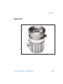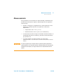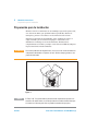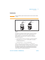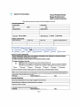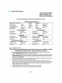
1
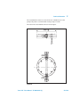
• • • • IdeaL , vacuum products • • • Turbo-V 81-T Models: 969-8905, 969-8906, 969-8907, 969-8908 Manual de Instrucciones User Manual • ••••• ••• • ••• ••• • • • •• • e;: • • (Spanish - pages 7-18) (English - pages 19-58) 87-900-984-01 (E) 0412011 . .· .. ....~:~ ... Agilent Technologies . .. . Notices © Agilent Technologies, Inc. 2011 No part of this manual may be reproduced in any form or by any means (including electronic storage and retrieval or translation into a foreign language) without prior agreement and written consent from Agilent Technologies, Inc. as governed by United States and international copyright laws. Manual Part Number Publication Number: 87-900-984-01 (E) Edition Edition 04/2011 Printed in ITALY Agilent Technologies Italia S.p.A. Vacuum Products Division Warranty The material contained in this document is provided “as is,” and is subject to being changed, without notice, in future editions. Further, to the maximum extent permitted by applicable law, Agilent disclaims all warranties, either express or implied, with regard to this manual and any information contained herein, including but not limited to the implied warranties of merchantability and fitness for a particular purpose. Agilent shall not be liable for errors or for incidental or consequential damages in connection with the furnishing, use, or performance of this document or of any information contained herein. Should Agilent and the user have a separate written agreement with warranty terms covering the material in this document that conflict with these terms, the warranty terms in the separate agreement shall control. Via F.lli Varian, 54 10040 Leinì (TO) ITALY Technology Licenses The hardware and/or software described in this document are furnished under a license and may be used or copied only in accordance with the terms of such license. contract clause. Use, duplication or disclosure of Software is subject to Agilent Technologies’ standard commercial license terms, and nonDOD Departments and Agencies of the U.S. Government will receive no greater than Restricted Rights as defined in FAR 52.227-19(c)(1-2) (June 1987). U.S. Government users will receive no greater than Limited Rights as defined in FAR 52.227-14 (June 1987) or DFAR 252.227-7015 (b)(2) (November 1995), as applicable in any technical data. Trademarks Windows and MS Windows are U.S. registered trademarks of Microsoft Corporation. Safety Notices CAUTION A CAUTION notice denotes a hazard. It calls attention to an operating procedure, practice, or the like that, if not correctly performed or adhered to, could result in damage to the product or loss of important data. Do not proceed beyond a CAUTION notice until the indicated conditions are fully understood and met. Restricted Rights Legend If software is for use in the performance of a U.S. Government prime contract or subcontract, Software is delivered and licensed as “Commercial computer software” as defined in DFAR 252.227-7014 (June 1995), or as a “commercial item” as defined in FAR 2.101(a) or as “Restricted computer software” as defined in FAR 52.227-19 (June 1987) or any equivalent agency regulation or WARNING A WARNING notice denotes a hazard. It calls attention to an operating procedure, practice, or the like that, if not correctly performed or adhered to, could result in personal injury or death. Do not proceed beyond a WARNING notice until the indicated conditions are fully understood and met. Turbo-V 81-T User Manual / 87-900-984-01 (E) Turbo-V 81-T Turbo-V 81-T Turbo-V 81-T User Manual / 87-900-984-01 (E) 3/228 Contents 3 Mode d’emploi 37 Normes de sécurité pour Pompe Turbomoléculaires Indications générales Stockage 39 41 Preparation pour l’installation 4 38 Installation 43 Utilisation 46 Entretien 47 Mise au rebut 48 42 Manual de istrucciones 49 Indicaciones de Seguridad para Bombas Turbomoleculares 50 Información general 51 Almacenamiento 53 Preparación para la instalación Instalación 55 Uso 57 54 Mantenimiento 58 Eliminación 5 59 Manual de Istruções 61 Indicações de Segurança para Bombas Turbomoleculares 62 Informações gerais 63 Armazenagem 65 6/228 Turbo-V 81-T User Manual / 87-900-984-01 (E) Contents Splošne informacije 175 Shranjevanje 176 Priprava za montažo 177 Montaža 178 Uporaba 180 Vzdrževanje 181 Odlaganje opadkov 181 16 Instructions for Use 183 Safety Guideline for Turbomolecular Pumps 184 General Information 185 Storage 186 Preparation for Installation 187 Installation 188 Use 190 Maintenance 191 Disposal 192 17 Technical Information 193 Description of the Turbo-V 81-T 194 Technical Specification 198 Turbo-V 81-T Outline 200 Inlet Screen Installation 203 Heater Band Installation 206 Turbo-V 81-T User Manual / 87-900-984-01 (E) 11/228 Contents Air Cooling Kit Installation 208 Water Cooling Kit Installation Vent Accessories 210 213 Vibration Isolator Installation 214 Typical Layout Diagram 215 Pump used in Presence of Magnetic Fields 220 Accessories and Spare Parts 221 Vent Valve Model Selection Table 12/228 222 Turbo-V 81-T User Manual / 87-900-984-01 (E) Turbo-V 81-T User Manual 4 Manual de istrucciones Indicaciones de Seguridad para Bombas Turbomoleculares 50 Información general 51 Almacenamiento 53 Preparación para la instalación 54 Instalación 55 Uso 57 Mantenimiento 58 Eliminación 59 Traducción de las instrucciones originales 49/228 4 Manual de istrucciones Indicaciones de Seguridad para Bombas Turbomoleculares Indicaciones de Seguridad para Bombas Turbomoleculares Las bombas Turbomoleculares descritas en el siguiente manual de instrucciones tienen una elevada cantidad de energía cinética debido a la alta velocidad de rotación en combinación a la masa específica de sus rotores. En el caso de un daño del sistema, por ejemplo por un contacto entre el rotor y el estator o por una rotura del rotor, la energía de rotación podría ser liberada. ¡ADVERTENCIA! 50/228 Para evitar daños a los equipos y prevenir lesiones a los operadores, es necesario seguir atentamente las instrucciones de instalación descritas en el presente manual! Turbo-V 81-T User Manual / 87-900-984-01 (E) Manual de istrucciones Información general 4 Información general Este equipo es para uso profesional. El usuario ha de leer atentamente el presente manual de instrucciones y cualquier otra información suplementaria facilitada por Agilent antes de usar el aparato. Agilent se considera libre de posibles responsabilidades debidas al incumplimiento total o parcial de las instrucciones, al uso impropio por parte de personal no preparado, a operaciones no autorizadas o a un uso contrario a las normas nacionales específicas. Las bombas de la serie Turbo V 81-T son bombas turbomoleculares para aplicaciones de alto y ultra alto vacío capaces de bombear cualquier tipo de gas o compuesto gaseoso no corrosivo. No son adecuadas para bombear líquidos ni partículas sólidas. El efecto de bombeo se obtiene mediante una turbina rotativa de alta velocidad (80000 r.p.m. máx.) movida por un motor eléctrico trifásico de alto rendimiento. El Turbo-V 81-T no posee ningún agente contaminante y por lo tanto es adecuado para aplicaciones que requieren un vacío’ “limpio”. A continuación se facilita toda la información necesaria para garantizar la seguridad del operador al usar el aparato. En el anexo “Technical Information” se facilita información más detallada. Turbo-V 81-T User Manual / 87-900-984-01 (E) 51/228 4 Manual de istrucciones Información general Este manual utiliza las convenciones siguientes: ¡ATENCIÓN! ¡ADVERTENCIA! NOTA 52/228 Los mensajes de atención se visualizan antes de los procedimientos que, al no respetarse, podrían provocar daños al equipo. Los mensajes de advertencia atraen la atención del operador sobre un procedimiento o una operación específica que, al no realizarse correctamente, podría provocar graves lesiones personales. Las notas contienen información importante extraída del texto. Turbo-V 81-T User Manual / 87-900-984-01 (E) Manual de istrucciones Almacenamiento 4 Almacenamiento Para garantizar el nivel máximo de funcionalidad y fiabilidad de las bombas turbomoleculares Agilent, deberán aplicarse las siguientes instrucciones: ¡ATENCIÓN! durante el transporte, desplazamiento y almacenamiento de las bombas no deberán superarse las siguientes condiciones ambientales: temperatura: entre –20 °C y 70 °C; humedad relativa: entre 0 y 95 % (no condensante); el cliente deberá activar siempre las bombas turbomoleculares en modalidad Soft-Start al recibirlas y ponerlas en funcionamiento por primera vez; el período máximo de almacenamiento de una bomba turbomolecular es de diez meses a contar de la fecha de envío al cliente. En caso de superarse por cualquier motivo el período máximo permitido de almacenamiento, será necesario devolver la bomba al fabricante. Para mayores informaciones al respecto, se ruega contactar con el representante local de Agilent. Turbo-V 81-T User Manual / 87-900-984-01 (E) 53/228 4 Manual de istrucciones Preparación para la instalación Preparación para la instalación El Turbo-V 81-T se suministra en un embalaje especial de protección; si se observan daños, que podrían haberse producido durante el transporte, ponerse en contacto con la oficina local de ventas. Durante la operación de desembalaje, tener cuidado de que no se caiga la bomba y de no someterla a golpes o vibraciones. No abandonar el embalaje en el medio ambiente. El material es completamente reciclable y cumple con la directiva CEE 85/399 para la preservación del medio ambiente. ¡ATENCIÓN! Para evitar problemas de desgasificación, no tocar con las manos desnudas los componentes destinados a exponerse al vacío. Utilizar siempre guantes u otra protección adecuada. Figura 1 NOTA 54/228 El Turbo-V 81-T no puede dañarse permaneciendo simplemente expuesto a la atmósfera. De todas formas, se aconseja mantener cerrada la bomba hasta que se instale en el sistema para evitar su posible contaminación por polvo. Turbo-V 81-T User Manual / 87-900-984-01 (E) Manual de istrucciones Instalación 4 Instalación ¡ATENCIÓN! Despegar el adhesivo y quitar el tapón de protección sólo al conectar la bomba al sistema. Figura 2 No instalar ni/o utilizar la bomba en lugares expuestos a agentes atmosféricos (lluvia, hielo y nieve), polvo y gases agresivos, en lugares explosivos o con alto riesgo de incendio. Durante el funcionamiento es necesario que se respeten las condiciones ambientales siguientes: presión máxima: 2 bares por encima de la presión atmosférica temperatura: de +5 °C a +35 °C (véase gráfico en el anexo “Technical Information”) humedad relativa: 0 – 95 % (no condensadora). Cuando existan campos electromagnéticos, la bomba ha de protegerse mediante pantallas oportunas. Véase el anexo “Technical Information” para más detalles. Las bombas turbomoleculares de la serie Turbo-V 81-T deben usarse exclusivamente con uno de los controladores Agilent y deben conectarse a una bomba primaria (véase esquema en “Technical Information”). Turbo-V 81-T User Manual / 87-900-984-01 (E) 55/228 4 Manual de istrucciones Instalación Los controladores disponibles son los siguientes: Rack controller 81-AG: 969-8988 Rack controller 81-AG RS232/485: 969-8989 Rack controller 81-AG Profibus: 969-8990 PCB 24 V: 969-9538 Navigator Controller 81AG 24 Vdc: 969-8995 Navigator Controller 81AG 100-240 Vac: 969-8996 El Turbo-V 81-T puede instalarse en cualquier posición. Fijar el Turbo-V 81-T en posición estable conectando la brida de entrada de la turbobomba a una contrabrida fija que puede resistir a un par de 250 Nm alrededor de su eje. Por ejemplo la brida ISO 63 puede ser fijada con mordazas en acero de alta resistencia (tipo modelo tipo Agilent IC 63250 DCMZ). La tabla siguiente describe el número de mordazas necesarios y con cual par de apriete apretarlos. Tab. 1 BRIDA TIPO DE MORDAZA N. PAR DE APRIETE ISO 63 Mordaza doble con rosca M10 4 22 Nm La turbobomba con brida de entrada ConFlat ha de fijarse a la cámara de vacío mediante los accesorios mecánicos específicos Agilent. Para más detalles véase el anexo “Technical Information”. NOTA ¡ATENCIÓN! El Turbo-V 81-T no puede fijarse utilizando su base. El Turbo-V 81-T pertenece a la segunda categoría de instalación (o sobretensión) prevista por la normativa EN 61010-1. Por lo tanto este dispositivo debe ser conectado a una línea de alimentación adecuada para dicha categoría. Para instalar los accesorios opcionales, véase “Technical Information”. 56/228 Turbo-V 81-T User Manual / 87-900-984-01 (E) Manual de istrucciones Uso 4 Uso En el manual de la unidad de control se encuentran todas las instrucciones para el correcto funcionamiento de la turbo-bomba. Leer atentamente este manual antes de su uso. Para obtener mejores presiones de máxima es posible calentar el sistema. Durante el calentamiento de la cámara de vacío la temperatura en la brida de entrada no debe superar los 120 °C con acoplamiento ConFlat y los 80 °C con acoplamiento ISO. Usar siempre refrigeración por agua durante las operaciones de calentamiento. ¡ADVERTENCIA! No hacer funcionar nunca la bomba si la brida de entrada no está conectada al sistema o no está cerrada con la brida de cierre. No tocar la turbo-bomba y sus posibles accesorios durante las operaciones de calentamiento. La alta temperatura puede provocar lesiones a las personas. ¡ATENCIÓN! Evítense golpes, oscilaciones o bruscos desplazamientos de la turbobomba durante su funcionamiento. Los cojinetes podrían dañarse. Para el envío de aire de la bomba utilizar aire o gas inerte sin polvo o partículas. La presión de entrada a través de la puerta deberá ser inferior a 2 bar (por encima de la presión atmosférica). Para bombear gases agresivos estas bombas están dotadas de una puerta específica mediante la cual es necesario suministrar a la bomba un caudal de gas inerte (Nitrógeno o Helio) para proteger los rodamientos (véase el anexo “Technical Information”). ¡ADVERTENCIA! Cuando la bomba se utiliza para bombear gases tóxicos, inflamables o radioactivos, seguir los procedimientos apropiados típicos de cada gas. No usar la bomba cuando haya gases explosivos. Turbo-V 81-T User Manual / 87-900-984-01 (E) 57/228 4 Manual de istrucciones Mantenimiento Mantenimiento Las bombas de la serie Turbo-V 81-T no requieren mantenimiento. Cualquier operación deberá ser realizada por personal autorizado. ¡ADVERTENCIA! Antes de realizar cualquier operación en el sistema desconectarlo de la corriente, enviar aire de la bomba abriendo la válvula oportuna, esperar hasta que el rotor se pare completamente y esperar a que la temperatura superficial de la bomba sea inferior a 50 ºC. En caso de avería se podrá utilizar el servicio de reparación Agilent o el “Agilent advanced exchange service”, que permite obtener un sistema regenerado para sustituir el averiado. NOTA Antes de enviar al fabricante una bomba para su reparación o “advanced exchange service”, es imprescindible cumplimentar y remitir a la oficina local de ventas la ficha de “Seguridad y Salud” adjunta al presente manual de instrucciones. Una copia de la misma se deberá introducir en el embalaje del sistema antes de enviarlo. En caso de que la bomba se tenga que desguazar, eliminarla respetando las normas nacionales específicas. 58/228 Turbo-V 81-T User Manual / 87-900-984-01 (E) Manual de istrucciones Eliminación 4 Eliminación Significado del logotipo "WEEE" presente en las etiquetas. El símbolo que se indica a continuación, es aplicado en observancia de la directiva CE denominada "WEEE". Este símbolo (válido sólo para los países miembros de la Comunidad Europea) indica que el producto sobre el cual ha sido aplicado, NO debe ser eliminado junto con los residuos comunes sean éstos domésticos o industriales, y que, por el contrario, deberá ser sometido a un procedimiento de recogida diferenciada. Por lo tanto, se invita al usuario final, a ponerse en contacto con el proveedor del dispositivo, tanto si éste es la casa fabricante o un distribuidor, para poder proveer a la recogida y eliminación del producto, después de haber efectuado una verificación de los términos y condiciones contractuales de venta. Turbo-V 81-T User Manual / 87-900-984-01 (E) 59/228 4 Manual de istrucciones Eliminación 60/228 Turbo-V 81-T User Manual / 87-900-984-01 (E) Turbo-V 81-T User Manual 16 Instructions for Use Safety Guideline for Turbomolecular Pumps General Information 185 Storage 186 Preparation for Installation 187 Installation 188 Use 189 Maintenance 191 Disposal 192 184 Original Instructions 183/228 16 Instructions for Use Safety Guideline for Turbomolecular Pumps Safety Guideline for Turbomolecular Pumps Turbomolecular pumps as described in the following operating manual contain a large amount of kinetic energy due to the high rotational speed in combination with the specific mass of their rotors. In case of a malfunction of the system for example rotor/stator contact or even a rotor crash the rotational energy may be released. WARNING! 184/228 To avoid damage to equipment and to prevent injuries to operating personnel the installation instructions as given in this manual should be strictly followed! Turbo-V 81-T User Manual / 87-900-984-01 (E) Instructions for Use 16 General Information This equipment is destined for use by professionals. The user should read this instruction manual and any other additional information supplied by Agilent before operating the equipment. Agilent will not be held responsible for any events occurring due to non-compliance, even partial, with these instructions, improper use by untrained persons, non-authorized interference with the equipment or any action contrary to that provided for by specific national standards. The Turbo-V 81-T is a turbo-molecular pump for high and ultra-high vacuum applications which can pump any type of non-corrosive gas or gas compound. It is not suitable for pumping liquids or solid particles. The pumping action is obtained through a high speed turbine (max. 80000 rpm) driven by a high-performance 3-phase electric motor. The Turbo-V 81-T is free of contaminating agents and, therefore, is suitable for applications requiring a "clean" vacuum. The following paragraphs contain all the information necessary to guarantee the safety of the operator when using the equipment. Detailed information is supplied in the appendix "Technical Information". This manual uses the following standard protocol: CAUTION! The caution messages are displayed before procedures which, if not followed, could cause damage to the equipment. WARNING! The warning messages are for attracting the attention of the operator to a particular procedure or practice which, if not followed correctly, could lead to serious injury. NOTE The notes contain important information taken from the text. Turbo-V 81-T User Manual / 87-900-984-01 (E) 185/228 16 Instructions for Use Storage Storage In order to guarantee the maximum level of performance and reliability of Agilent Turbomolecular pumps, the following guidelines must be followed: CAUTION! 186/228 when shipping, moving and storing pumps, the following environmental specifications should not be exceeded: temperature range: -20 °C to 70 °C relative humidity range: 0 to 95 % (non condensing) the turbomolecular pumps must be always soft-started when received and operated for the first time by the customer the shelf life of a turbomolecular pump is 10 months from the shipping date. If for any reason the shelf life time is exceeded, the pump has to be returned to the factory. Please contact the local Agilent Vacuum Sales and Service representative for informations. Turbo-V 81-T User Manual / 87-900-984-01 (E) Instructions for Use 16 Preparation for Installation The Turbo-V 81-T is supplied in a special protective pack-ing. If this shows signs of damage which may have occurred during transport, contact your local sales office. When unpacking the pump, be sure not to drop it and avoid any kind of sudden impact or shock vibration to it. Do not dispose of the packing materials in an unauthorized manner. The material is 100 % recyclable and complies with EEC Directive 85/399. CAUTION! In order to prevent outgassing problems, do not use bare hands to handle components which will be exposed to vacuum. Always use gloves or other appropriate protection. Figure 1 NOTE Normal exposure to the environment cannot damage the Turbo-V 81-T. Nevertheless, it is advisable to keep it closed until it is installed in the system, thus preventing any form of pollution by dust. Turbo-V 81-T User Manual / 87-900-984-01 (E) 187/228 16 Instructions for Use Installation Installation CAUTION! Do not remove the adhesive and protective cap before connecting the turbopump to the system. Figure 2 Do not install or use the pump in an environment exposed to atmospheric agents (rain, snow, ice), dust, aggressive gases, or in explosive environments or those with a high fire risk. During operation, the following environmental conditions must be respected: maximum pressure: 2 bar above atmospheric pressure temperature: from +5 °C to +35 °C (see the diagram pres-suretemperature in the appendix “Technical Information”) relative humidity: 0 – 95 % (non-condensing) In the presence of magnetic fields the pump must be protected using a ferromagnetic shield. See the appendix "Technical Information" for detailed information. The Turbo-V 81-T pumps must be used in conjunction with one of the suitable Agilent controller and they must be connected to a primary pump (see "Technical Information"). 188/228 Turbo-V 81-T User Manual / 87-900-984-01 (E) Instructions for Use 16 The available controllers are the following: Rack controller 81-AG: 969-8988 Rack controller 81-AG RS232/485: 969-8989 Rack controller 81-AG Profibus: 969-8990 PCB 24 V: 969-9538 Navigator Controller 81AG 24 Vdc: 969-8995 Navigator Controller 81AG 100-240 Vac: 969-8996 The Turbo-V 81-T can be installed in any position. Fix the Turbo-V 81-T in a stable position connecting the inlet flange of the turbopump to a fixed counter-flange capable of withstanding a torque of 250 Nm around its axis. For example the ISO 63 flange can be fixed using high strength steel clamps (as Agilent model IC 63250 DCMZ). The following table shows the necessary number of clamps and the relevant fixing torque. Tab. 1 FLANGE FIXING DEVICE N. FIXING TORQUE ISO 63 M10 clamps 4 22 Nm The turbopump with ConFlat inlet flange must be fixed to the vacuum chamber by means of the appropriate Agilent hardware. See the appendix "Technical Information" for a detailed description. NOTE CAUTION! The Turbo-V 81-T cannot be fixed by means of its base. The Turbo-V 81-T belongs to the second installation (or overvoltage) category as per directive EN 61010-1. Connect the device to a mains line that satisfy the above category. For installation of optional accessories, see "Technical Information". Turbo-V 81-T User Manual / 87-900-984-01 (E) 189/228 16 Instructions for Use Use Use All the instructions to correctly use the turbopump are contained in the controller manual. Read carefully this manual before use the pump. To obtain better limit pressures it is possible to heat the pump. While heating the vacuum chamber, the temperature of the inlet flange must not exceed 120 °C for a ConFlat flange and 80 °C for a ISO flange. While heating always use the water cooling. WARNING! Never use the turbopump when the inlet flange is not connected to the vacuum chamber. Do not touch the turbopump or any of its accessories during the heating process. The high temperatures may cause burns. CAUTION! Avoid impacts, oscillations or harsh movements of the pump when in operation. The bearings may become damaged. Use air or inert gas free from dust or particles for venting the pump. The pressure at the vent port must be less than 2 bar (above atmospheric pressure). For pumping aggressive gases, these pumps are fitted with a special port to allow a steady flow of inert gas (like Nitrogen or Helium) for pump bearing protection (see the appendix "Technical Information"). WARNING! When employing the pump for pumping toxic, flammable, or radioactive gases, please follow the required procedures for each gas disposal. Do not use the pump in presence of explosive gases. 190/228 Turbo-V 81-T User Manual / 87-900-984-01 (E) Instructions for Use 16 Maintenance The Turbo-V 81-T series pumps does not require any maintenance. Any work performed on the system must be carried out by authorized personnel. WARNING! Before carrying out any work on the system, disconnect it from the mains, vent the pump by opening the appropriate valve, wait until the rotor has stopped turning and wait until the surface temperature of the pump falls below 50 °C. In the case of breakdown, contact your local Agilent service center who can supply a reconditioned system to replace that broken down. NOTE Before returning the pump to the constructor for repairs, or advanced exchange service, the "Health and Safety" sheet attached to this instruction manual must be filled-in and sent to the local sales office. A copy of the sheet must be inserted in the system package before shipping. If a system is to be scrapped, it must be disposed of in accordance with the specific national standards. Turbo-V 81-T User Manual / 87-900-984-01 (E) 191/228 16 Instructions for Use Disposal Disposal Meaning of the "WEEE" logo found in labels The following symbol is applied in accordance with the EC WEEE (Waste Electrical and Electronic Equipment) Directive. This symbol (valid only in countries of the European Community) indicates that the product it applies to must NOT be disposed of together with ordinary domestic or industrial waste but must be sent to a differentiated waste collection system. The end user is therefore invited to contact the supplier of the device, whether the Parent Company or a retailer, to initiate the collection and disposal process after checking the contractual terms and conditions of sale. 192/228 Turbo-V 81-T User Manual / 87-900-984-01 (E) Turbo-V 81-T User Manual 17 Technical Information Description of the Turbo-V 81-T 194 Pump Description 194 Technical Specification 198 Turbo-V 81-T Outline 200 Inlet Screen Installation 203 Heater Band Installation 206 Air Cooling Kit Installation 208 Water Cooling Kit Installation 210 Vent Accessories 213 Vibration Isolator Installation 214 Typical Layout Diagram 215 With Navigator Controller 215 With Standard Rack Controller 216 Connection A - High Vacuum Flange 217 Connection Configurations 218 Connection B - Fore-Vacuum Pump 219 Connection C - Electrical 219 Pump used in Presence of Magnetic Fields 220 Accessories and Spare Parts 221 Vent Valve Model Selection Table 222 Original Instructions 193/228 17 Technical Information Description of the Turbo-V 81-T Description of the Turbo-V 81-T The Turbo-V 81-T pump is available in four versions. The difference among the four versions lies purely in the high vacuum connection. The four versions are: Model 969-8905 with ISO 63 high vacuum flange; Model 969-8906 with KF 40 NW high vacuum flange; Model 969-8907 with ConFlat 4.5" external diameter high vacuum flange; Model 969-8908 with ConFlat 2.75” external diameter high vacuum flange. Pump Description The pump consists of a high frequency motor driving a turbine fitted with 9 bladed stages. The turbine rotates in an anticlockwise direction when viewed from the high vacuum flange end. The turbine is made of high-strength aluminium al-loy, machined from a single block. Figure 3 194/228 Model 969-8905 Turbo-V 81-T User Manual / 87-900-984-01 (E) Technical Information Figure 4 Model 969-8906 Figure 5 Model 969-8907 Figure 6 Model 969-8908 Turbo-V 81-T User Manual / 87-900-984-01 (E) 17 195/228 17 Technical Information Description of the Turbo-V 81-T Proceeding from the high vacuum to the forevacuum region, the turbine stages sequence is: 1st stage with a blade angle of 40°, 2nd stage with a blade angle of 30°, 3rd stage with a blade angle of 24°, 4th and 5th stages with a blade angle of 18°, 6th stage with a blade angle of 14°; 7th, 8th and 9th stages with a blade angle of 12°. The turbine rotor is supported by permanently lubricated high precision ceramic ball bearings installed on the forevacuum side of the pump. The static blades of the stator are made of stainless steel. These are supported and accurately positioned by spacer rings. During normal operation, the motor is fed with a voltage of 54 Vac three-phase at 1350 Hz (max). To reduce losses during start-up to a minimum, the frequency increases according to a ramp with a higher initial voltage/frequency ratio. The pump can be water cooled or air cooled: in the first case the customer can use a dedicated external plate made of nickel-plated brass, in the second case an external optional fan is available. A thermistor sensor is mounted near the upper bearing to prevent the pump from overheating. The pump is balanced after assembly with a residual vibration amplitude less than 0.01 m. The pump can operate in any position and can be supported on the high vacuum flange. The connection of the forevacuum on the side of the pump is a KF 16 NW flange. 196/228 Turbo-V 81-T User Manual / 87-900-984-01 (E) Technical Information 17 PUMP CONTROLLER CONNECTOR FOREPUMP CONNECTOR Figure 7 Turbo-V 81-T User Manual / 87-900-984-01 (E) 197/228 17 Technical Information Technical Specification Technical Specification Tab. 2 Technical Specification Pumping speed With ISO 63 or CFF 4.5” N2: 77 l/s He: 65 l/s H2: 50 l/s Compression ratio 198/228 With KF 40 NW or CFF 2.75” N2: 50 l/s He: 56 l/s H2: 46 l/s N2: >7 x 10⁶ He: 5 x 10³ H2: 3 x 10² Base pressure * (with recommended forepump) mechanical: 5 x 10⁻⁹ mbar (3.8 x 10⁻⁹ Torr) diaphragm: 5 x 10⁻⁸ mbar (3.8 x 10⁻⁸ Torr) Inlet flange ISO 63 CFF 4.5” O.D. Foreline flange KF16 NW Rotational speed 1350 Hz (max) Start-up time < 60 seconds Cooling requirements Natural air convection Forced air or water optional Recommended forepump mechanical: Agilent DS 42 – DS 102 dry pump: Agilent SH 100 Operating position any Coolant water flow: 10 l/h (0.05 GPM) temperature: + 15 °C to + 35 °C pressure: 2 to 4 bar (30 to 60 Psi) Operating ambient temperature with natural air convection +5 °C to +25 °C Operating ambient temperature with forced air cooling or water +5 °C to +35 °C Bakeout temperature 120 °C at inlet flange max. (CF flange) 80 °C at inlet flange max. (ISO flange) Vibration level (displacement) 0.01 Pm at inlet flange Noise level d 45 dB (A) at 1 meter KF 40 NW CFF 2.75” O.D. Turbo-V 81-T User Manual / 87-900-984-01 (E) Technical Information Compliance with: UNI EN 292-1 UNI EN 292-2 EN-CENELEC 55011 IEC 1000-4-2 (ex 801-2) IEC 1000-4-3 (ex 801-3) IEC 1000-4-4 (ex 801-4) EN 61010-1 (IEC 1010-1) EN 1012-2 Storage temperature -20 °C to +70 °C Input 60 Vac, three phase, 1350 Hz (max) 50 W max Lubricant permanent lubrication Installation category II Pollution degree 2 Storage temperature - 20 °C to + 70 °C Weight kg (lbs): ISO 63: 1.83 (4.03) KF 40: 1.80 (3.97) CFF 4.5”: 2.62 (5.78) CFF 2.75”: 2.59 (5.71) 17 * (According to standard DIN 28 428, the base pressure is that measured in a leak-free test dome, 48 hours after the completion of test dome bake-out, with a Turbopump fitted with a ConFlat flange and using the recommended pre-vacuum pump) NOTE When the Turbo-V 81-T has been stored at a temperature less than 5 °C, wait until the system has reached the above mentioned temperature. Turbo-V 81-T User Manual / 87-900-984-01 (E) 199/228 17 Technical Information Turbo-V 81-T Outline Turbo-V 81-T Outline The following figure shows the Turbo-V 81-T outlines (dimensions are in inches [mm]). Figure 8 200/228 Turbo-V 81-T outline Turbo-V 81-T User Manual / 87-900-984-01 (E) Technical Information Figure 9 Graph of pumping speed vs inlet pressure with a 8 m3/h mechanical pump Figure 10 Graph of compression ratio vs foreline pressure Turbo-V 81-T User Manual / 87-900-984-01 (E) 17 201/228 17 Technical Information Turbo-V 81-T Outline Figure 11 202/228 Graph of Nitrogen throughput against inlet pressure using a DS102 as forevacuum pump Turbo-V 81-T User Manual / 87-900-984-01 (E) Technical Information 17 Inlet Screen Installation Figure 12 Figure 13 The inlet screens mod. 969-9300 and 969-9309 prevent the blades of the pump from being damaged by debris greater than 0.7 mm diameter. The inlet screen, however, does reduce the pumping speed by about 10 %. The inlet screen is fitted in the upper part of the pump, as shown in the figure. Turbo-V 81-T User Manual / 87-900-984-01 (E) 203/228 17 Technical Information Inlet Screen Installation Figure 14 The screen can be mounted on each pump. The screen can be removed as shown in the following figure. Figure 15 204/228 Turbo-V 81-T User Manual / 87-900-984-01 (E) Technical Information 17 The following figure shows the overall flange dimensions with the protection screen fitted on pump with ISO flange and pump with CFF flange (dimensions are in inches [mm]). Figure 16 Turbo-V 81-T User Manual / 87-900-984-01 (E) 205/228 17 Technical Information Heater Band Installation Heater Band Installation Figure 17 The heater band model 969-9801 and 969-9802 can be used to heat the pump casing when a bakeout is needed. The heater band is applied to the upper part of the pump casing, as shown in the figure, and heats it to a temperature of about 80 °C. The heater band must be mounted such that there is perfect thermal contact with the pump wall to obtain fast and efficient heating. Figure 18 206/228 Turbo-V 81-T User Manual / 87-900-984-01 (E) Technical Information 17 Switch on the heater while the turbopump is in operation. In the event of turbopump overheat, the pump will be automatically cut out by the thermistor sensor. NOTE CAUTION! The turbopump must be "baked" only when operat-ing with an inlet pressure less than 10-4 mbar and with water cooling. If the chamber of the system is "baked" at a high temperature, a shield should be installed to pre-vent thermal radiation heating the high vacuum flange on the pump. The maximum temperature allowed for the inlet flange is 120 °C. Turbo-V 81-T User Manual / 87-900-984-01 (E) 207/228 17 Technical Information Air Cooling Kit Installation Air Cooling Kit Installation An air cooling kit (mod. 969-9290) is available for cooling the pump during heavy operational conditions and whenever the natural air convection is not sufficient. Figure 19 Fan specifications: air flow: 12.8 l/s (27.1 CFM) input voltage: 24 Vdc dimensions: 60 x 60 x 25 mm power: 2.60 W The fan bracket is shaped so that it can be mounted close to the pump and in different positions. To fix the fan to the Turbo-V 81-T case execute the following procedure (see the following figure): 208/228 1 Fix the fan to the suitable bracket by means of the furnished screws; 2 Fix the bracket to the pump body; 3 Connect the fan supply to the P4 connector of the controller. Turbo-V 81-T User Manual / 87-900-984-01 (E) Technical Information 17 Figure 20 Figure 21 Figure 22 Turbo-V 81-T User Manual / 87-900-984-01 (E) 209/228 17 Technical Information Water Cooling Kit Installation Water Cooling Kit Installation Two types of water cooling kits are available to be mounted when the pump is used under heavy load conditions or when air cooling is insufficient. The two model part numbers are: 969-9823 (metallic model), and 969-9824 (plastic model). Figure 23 CAUTION! The items of the plastic model kit must be assembled as shown in the following figure Figure 24 210/228 Turbo-V 81-T User Manual / 87-900-984-01 (E) Technical Information 17 The assembled kit must be screwed into the suitable holes of the pump body with a recommended closing torque of 5 Nm. The water kit is assembled as shown in the figure. Figure 25 Turbo-V 81-T User Manual / 87-900-984-01 (E) 211/228 17 Technical Information Water Cooling Kit Installation 1 Connect the plate to the pump bottom with four screws M3x20 Figure 26 2 Assemble the metal or the plastic kit as shown. Cooling may be carried out either through an open circuit with eventual discharge of the water, or using a closed circuit cooling system. The water temperature must be between +15 °C and +35 °C, with an inlet pressure between 2 and 4 bar. NOTE 212/228 The water electrical conductance must be 500 μs/cm. When the conductance is higher, in closed water circuit, the use of up to 20 % of Ethyl-Glycole is suggested. Turbo-V 81-T User Manual / 87-900-984-01 (E) Technical Information 17 Vent Accessories The vent valve allow to avoid undesired venting of the pump during temporary power failure and enables an automatic vent operation. There are several vent valves available and each vent valve has to be driven by its own control unit. NOTE Refer to the Vent Valve Model Selection table to choose the valve and the related control unit. NOTE Refer to the control unit manual for the pump-valve-controller interconnections. Refer to the vent valve manual and follow the in-structions to properly vent the turbomolecular pump. To install the vent valve, unscrew the threaded plug (see figure below). Figure 27 Then screw the vent valve into the pump and tighten it using a 16 mm hexagonal spanner with a torque of 2.5 Nm. Turbo-V 81-T User Manual / 87-900-984-01 (E) 213/228 17 Technical Information Vibration Isolator Installation Figure 28 CAUTION! Do not overtighten the valve as this may damage the thread on the pump. Then connect the cable from the valve to the suitable connector on the controller. Vibration Isolator Installation Two vibration isolators for ISO and CFF inlet flange version pumps are available as accesso-ries. The two model part numbers are the following: model 969-9375 for ISO 63 flange; model 969-9376 for CFF 4.5” flange. They typically reduce the vibration transmitted from the Turbo-V 81-T to the system by a factor of 20. Please refer to the relevant instruction manual. 214/228 Turbo-V 81-T User Manual / 87-900-984-01 (E) Technical Information 17 Typical Layout Diagram With Navigator Controller Figure 29 1 Turbo-V Navigator controller 2 Vent valve 3 Vacuum pump shut-off valve (optional) 4 System vent valve (optional) 5 Vacuum chamber 6 Ionization gauge 7 Fore-vacuum pump connecting flange 8 Oil mist eliminator 9 Fore-vacuum pump with internal one-way valve 10 Fore-vacuum pump control relay 11 Connection for water cooling 12 Roughing line with valve (optional) Turbo-V 81-T User Manual / 87-900-984-01 (E) 215/228 17 Technical Information Typical Layout Diagram 13 Turbopump 14 Fan 15 Flexible connection With Standard Rack Controller Figure 30 1 Turbo-V standard rack controller 2 Vent valve 3 Vacuum pump shut-off valve (optional) 4 System vent valve (optional) 5 Vacuum chamber 6 Ionization gauge 7 Fore-vacuum pump connecting flange 8 Oil mist eliminator 9 Fore-vacuum pump with internal one-way valve 10 Fore-vacuum pump control relay 11 Connection for water cooling 216/228 Turbo-V 81-T User Manual / 87-900-984-01 (E) Technical Information 17 12 Roughing line with valve (optional) 13 Turbopump 14 Flexible connection Connection A - High Vacuum Flange To connect the Turbo-V 81-T pump to the ISO inlet flange, remove the outer ring and position the centering ring as shown in the figure. Figure 31 Then fix the two flanges with the clamps or claws as shown in the figure. Figure 32 Turbo-V 81-T User Manual / 87-900-984-01 (E) 217/228 17 Technical Information Typical Layout Diagram For ConFlat flange connections we recommend using Agilent hardware. To facilitate assembly and dismantling, apply Felpro C-100 high temperature lubricant to the screw threads protruding from the flange and between the nuts and flange. Attach the units and tighten each one in turn. Repeat the sequential tightening until the flange faces meet. CAUTION! Exercise care when tightening nuts and bolts to avoid creating dents in the envelope as this may cause the pump rotor to lock. Connection Configurations Figure 33 218/228 Turbo-V 81-T User Manual / 87-900-984-01 (E) Technical Information 17 Connection B - Fore-Vacuum Pump A flange KF 16 NW is available to connect the Turbo-V 81-T pump to the fore-vacuum pump. A hose or vacuum approved pipe can be used. If a rigid pipe is used, any vibration generated by the mechanical pump must be eliminated through the use of bellows. NOTE The Turbo-V 81-T pump is characterized by its high compression ratio also for oil vapors. When using a mechanical oil-sealed pump, it is advisable to install a suitable trap between the turbopump and the fore-vacuum pump in order to prevent oil backstreaming. Connection C - Electrical Figure 34 The turbopump is connected to the controller through an 6-pin connector. Pins B, C and D are the 3-phase supply to the motor, pins A and F are connected to the temperature sensor (NTC type, 30 K resistance at 25 °C) and pin E is connected to the pump ground. If the temperature sensor is disconnected, the pump will not start. To prevent damage to the pump when the temperature exceeds 60 °C, the sensor automatically cuts out the power supply. Turbo-V 81-T User Manual / 87-900-984-01 (E) 219/228 17 Technical Information Pump used in Presence of Magnetic Fields Pump used in Presence of Magnetic Fields Magnetic fields induce eddy currents in the rotor of a turbomolecular pump that tend to oppose to its rotation. The result is increased electrical power consumption by the motor, most of which is dissipated in the rotor. Since the rotor is not in contact with the stator the above power can leave the rotor mainly by radiation and hence the rotor may be overheated while static parts of the pump remain cool. This effect is strongly dependant from the intensity, time function and distribution of the magnetic field. In general, therefore, an increase in pump current can be expected. If this increase is lower than 50 % of the current value drawn by the motor in high vacuum opera-tion, no particular problem should be expected. However if the effect is grater, than the case should be carefully reviewed by Agilent's special-ist. As a matter of fact, in case of high magnetic fields, also important forces might be generated and applied to the rotor. 220/228 Turbo-V 81-T User Manual / 87-900-984-01 (E) Technical Information 17 Accessories and Spare Parts Tab. 3 Accessories and Spare Parts DESCRIPTION PART NUMBER Inlet screen, DN 40 969-9309 Inlet screen, DN 63 969-9300 Heater band 220 V 969-9801 Heater band 120 V 969-9802 Metallic water cooling kit 969-9823 Plastic water cooling kit 969-9824 Air cooling kit (0.5 m cable) 969-9290 Air cooling kit extension cable (5 m) 969-9940 Pump extension cable 969-9942 Vibration damper DN 63 969-9375 Vibration damper CFF 4.5" 969-9376 Mechanical pump DS 102 949-9315 Mechanical pump DS 42 949-9309 Dry scroll SH 100 SH01001 UNIV Dry scroll SH 110 SH01101 UNIV Rack controller 81-AG base 969-8988 Rack controller 81-AG RS232/485 969-8989 Rack controller 81-AG Profibus 969-8990 PCB 24 V 969-9538 Turbo-V 81-AG Navigator Controller 24 Vdc 969-8995 Turbo-V 81-AG Navigator Controller 100-240 Vac 969-8996 For a complete overview of Agilent's extensive product lines, please refer to the Agilent catalog. Turbo-V 81-T User Manual / 87-900-984-01 (E) 221/228 17 Technical Information Vent Valve Model Selection Table Vent Valve Model Selection Table Tab. 4 222/228 Vent valve model selection table CONTROL UNIT MODEL VENT VALVE PART NUMBER Turbo-V 81-AG Navigator Controller (cable 0.7 m) (any version) N.O. 969-9844 Turbo-V 81-AG Rack Controller (cable 0.7 m) (any version) N.O. 969-9844 Controller TV70 Navigator (P/N 969-8970, 969-8971) 969-9834 Turbo-V 70 Rack controller (P/N 969-9405, 969-9505) 969-9843 Turbo-V 81-T User Manual / 87-900-984-01 (E) · .. ...,-~:~ ... Agilent Technologies ; ., Vacuum Products Division Dear Customer, Thank you for purchasing an Agilent vacuum product. At Agilent Vacuum Products Division we make every effort to ensure that you will be satisfied with the product and/or service you have purchased. As part of our Continuous Improvement effort, we ask that you report to us any problem you may have had with the purchase or operation of our products. On the back side you find a Corrective Action request form that you may fill out in the first part and return to us. This form is intended to supplement normal lines of communications and to resolve problems that existing systems are not addressing in an adequate or timely manner. Upon receipt of your Corrective Action Request we will determine the Root Cause of the problem and take the necessary actions to eliminate it. You will be contacted by one of our employees who will review the problem with you and update you, with the second part of the same form, on our actions. Your business is very important to us. Please, take the time and let us know how we can improve. Sincerely. Giampaolo LEVI Vice President and General Manager Agilent Vacuum Products Division Note: Fax or mail the Customer Request for Action (see backside page) to Agilent Vacuum Products Division (Torino) - Quality Assurance or to your nearest Agilent representative for onward transmission to the same address. CUSTOMER REQUEST FOR CORRECTIVE I PREVENTIVE I IMPROVEMENT ACTION TO: AGILENT VACUUM PRODUCTS DIVISION TORINO - QUALITY ASSURANCE FAX N°: XXXX-Oll-99793S0 ADDRESS: AGILENT TECHNOLOGIES ITALIA S.p.A. - Vacuum Products Division Via F.III Varian, S4 -10040 Lelnl (TO) -Italy E-MAIL: [email protected] NAME COMPANY FUNCTION ADDRESS: TEL. N": FAX N": E-MAIL: PROBLEM / SUGGESTION: REFERENCE INFORMATION (model n°, serial n°, ordering information, time to failure after installation, etc.): DATE CORRECTIVE ACTION PLAN / ACTUATION (by AGILENT VPD) LOG N° xxx =Code for dialing Italy from your country (es. 01139 from USA; 00139 from Japan, etc.) .::~:~:... Agilent Technologies ": -, ....... . .. . ...• ...... ;•... Agilent Technologies Vacuum Products Division Instructions for returning products Dear Customer: Please follow these instructions whenever one of our products needs to be retumed. 11 Complete the attached Request for Return form and send it to Agilent Technologies ~see below). taking particular care to identify all products that have pumped or been exposed to any toxic or hazardous materials. 21 After evaluating the information. Agilent Technologies will provide you with a Return Authorization (RA) number via email or fax. as requested. Note: Depending on the type of return. a Purchase Order may be required at the time the Request for Return is submitted. We will quote any necessary services (evaluation. repair. special cleaning. eg) . 3) Important steps for the shipment of returning product • Remove all accessories from the core product (e.g. inlet screens. vent valves). • Prior to shipment. drain any oils or other liquids. purge or flush all gasses. and wipe off any excess residue. • If ordering an Advance Exchange product. please use the packaging from the Advence Exchange to return the defective product • Seal the product in a plastic bag. and package product carefully to avoid damage in transit. You are responsible for loss or damage in transit. • Agilent Technologies is not responsible for returning customer provided packaging or containers. • Clearly label package with RA number. Using the shipping label provided will ensure the proper address and RA number are on the package. Packages shipped to Agilent without a RA clearly written on the outside cannot be accepted and will be return ed. 4) Return only products for which the RA was issued. 5) Product being retumed under a RA must be received within 15 business days. 6) Ship to the location specified on the printable label, which will be sent, along with the RA number, as soon as we have received all of the required information. Customer is responsible for freight charges on returning product. 7) Return shipments must comply with all applicable Shipping Regulations (lATA. DOT. etc.) and carrier requirements. RETURN THE COMPLETED REQUEST FOR RETURN FORM TO YOUR NEAREST LOCATION: EUROPE: Fax: 00 39 011 9979 330 Fax Free: 00 800 345 345 00 Toll Free: 00 800 234 234 00 vpt -custo [email protected] NORTH AMERICA: PACIFIC RIM: Fax: 1 781 860 9252 Toll Free: 800 882 7426. Option 3 [email protected] please visit our website for individual office information http://www.agilent.com Pg 113 · .' · · :~;t · Agilent Technologies Vacuum Products Division Request for Return Form (Health and Safety Certification) Please read important policy information on Page 3 that applies to all returns. 1) CUSTOMER INFORMATION Company Name: Contact Name: Tel: Email: Fax: Customer Ship To: Customer Bill To: Eurol!e on I~f VAT reg. Number: USA/Canada only:: DTaxable D Non-taxable 2 PRODUCT IDENTIFICATION Product Description Agilent PIN Agilent SIN Original Purchasing Reference 3) TYPE OF RETURN (Chao.. ana from each row and supply Purchase Order if requesting a billable service) 3A. D Non·Biliable 3B. DExchange D Billable DRepair ..... New PO # (hard copy must be submitted with this form): DUpgrade DConsignment/Demo DCalibration DEvaluation DReturn for Credit 4 HEALTH and SAFETY CERTIFICATION AGiLENT TECHNOLOGIES CANNOT ACCEPT ANY PRODUCTS CONTAMINATED WITH BIOLOGICAL OR EXPLOSIVE HAZARDS, RADIOACTIVE MATERIAL OR MERCURY AT ITS FACILOY. Call Agilent Technologies to discuss alternatives if this requirement presents a problem. The equipmentlistad above (chack ana): D HAS NOT pumped or been exposed to any toxic or hazardous materials. OR D HAS pumped or been exposed to the following toxic or hazardous materials. If this box is checked. the following information must also be filled out. Check boxes for all materials to which product(s) pumped or was exposed: DToxic D Corrosive D Reactive D Flammable D Explosive D Biological D Radioactive List all toxiclhazardous materials. Include product name, chemical name, and chemical symbol or formula: NOTE: If a product is received at Agilent which is contaminated with a toxic or hazardous material that was not disclosed, .... c_lIIIr will" hid JllllJlonsibl8 for all costs incurred to ensure the safe handling of the product. and is liable for any harm or iniury to Agilent employees as well as to any third party occurring as a result of exposure to toxic or hazardous materials present in the product Print Neme: Authorized Signature: ............................ Date: 5 FAILURE INFORMATION: Failure Mode (REQUIRED FIELD. See next page for suggestions of failure terms): Detailed Description of Malfunction: (Please provide the error message) Application (system and model): I understand and agree to the terms of Section 6, Page 3/3. Print Nama: Authorized Signatura: ............................ PgZ/3 Data: " . " ...~:~. . Agilent Technologies " : -, Vacuum Products Division Request for Return Form (Health and Safety Certification) Please use these Failure Mode to describe the concern about the product on Page 2. APPARENT DEFECT/MALFUNCTION - Does not start - Does not spin freely - Does not reach full speed - Mechanical Contact - Cooling defective - Bad feedthrough - Vacuum leak - Error code on display TURBO PUMPS and TURBO CONTROLLERS POSITION PARAMETERS Power. - Noise - Vertical Current - Vibrations -Horizontal Temp 1: -Upside-down -Leak -Overtemperature -Other: Temp 2: -Clogging ...................... OPERATING TIME: ION PUMPS/CONTROLLERS - Poor vacuum - High voltage problem - Other - Cannot calibrate - Vacuum system unstable - Failed to start Rotational Speed: Inlet Pressure: Foreline Pressure: Purge flow: VALVES/COMPONENTS - Main seal leak - Bellows leak - Solenoid failure - Damaged flange -Other - Damaged sealing area LEAK DETECTORS -No zero/high backround - Cannot reach test mode - Other INSTRUMENTS - Gauge tube not working - Display problem - Communication failure - Degas not working - Error code on display - Other SCROLL AND ROTARY VANE PUMPS - Pump doesn't start - Noisy pump (describe) - Doesn't reach vacuum - Over temperature - Pump seized - Other DIFFUSION PUMPS - Heater failure - Doesn't reach vacuum - Vacuum leak - Electrical problem - Cooling coil damage - Other Section 6) ADDITIONAL TERMS Please read the terms and conditions below as they apply to all returns and are in addition to the Agilent Technologies Vacuum Product Division - Products and Services Terms of Sale. • Customer is responsible for the freight charges for the returning product Return shipments must comply with all applicable Shipping Regulations (lATA, DOT, etc_) and carrier requirements, • Customers receiving an Advance Exchange product agree to return the defective, rebuildable part to Agilent Technologies within 15 business daYIL Failure to do so or returning a non-rebuildable part (crashed) will result in an invoice for the non-retumed/non-rebuildable part • Retu ms for cred it toward the purchase of new or refurbished Products are subject to prior Agilent approval and may incur a restocking fee, Please reference the original purchase order number_ • Units returned for evaluation will be evaluated, and a quote fo r repair will be issued_ If you choose to have the unit repaired. the cost of the evaluation will be deducted from the final repair pricing. A Purchase Order for the final repair price should be issued within 3 weeks of quotation date, Units without a Purchase Order for repair will be returned to the customer, and the evaluation fee will be invoiced_ • A Special Cleaning fee will apply to all exposed products per Section 4 of this document • If request ing a calibration service. units must be functionally capable of being calibrated_ Pg 3/3 Request for Return Form Sales and Service Offices United States Agilent Technologies Vacuum Products Division 121 Hartwell Avenue Lexington, MA 02421 - USA Tel.: +1 781 861 7200 Fax: +1 781 860 5437 Toll-Free: +1 800 882 7426 India Agilent Technologies India Pvt. Ltd. Vacuum Product Division G01. Prime corporate Park, 230/231, Sahar Road, Opp. Blue Dart Centre, Andheri (East), Mumbai – 400 099.India Tel: +91 22 30648287/8200 Fax: +91 22 30648250 Toll Free: 1800 113037 Italy Agilent Technologies Italia S.p.A. Vacuum Products Division Via F.lli Varian, 54 10040 Leinì, (Torino) - Italy Tel.: +39 011 997 9111 Fax: +39 011 997 9350 Toll-Free: 00 800 234 234 00 Southeast Asia Agilent Technologies Sales Sdn Bhd Vacuum Products Division Unit 201, Level 2 uptown 2, 2 Jalan SS21/37, Damansara Uptown 47400 Petaling Jaya, Selangor, Malaysia Tel : +603 7712 6106 Fax: +603 6733 8121 Taiwan Agilent Technologies Taiwan Limited Vacuum Products Division (3F) 20 Kao-Shuang Rd., Pin-Chen City, 324 Taoyuan Hsien , Taiwan, R.O.C. Tel. +886 34959281 Toll Free: 0800 051 342 Canada Central coordination through: Agilent Technologies Vacuum Products Division 121 Hartwell Avenue Lexington, MA 02421 - USA Tel.: +1 781 861 7200 Fax: +1 781 860 5437 Toll-Free: +1 800 882 7426 Japan Agilent Technologies Japan, Ltd. Vacuum Products Division 8th Floor Sumitomo Shibaura Building 4-16-36 Shibaura Minato-ku Tokyo 108-0023 - Japan Tel.: +81 3 5232 1253 Fax: +81 3 5232 1710 Toll-Free: 0120 655 040 UK and Ireland Agilent Technologies UK, Ltd. Vacuum Products Division 6 Mead Road Oxford Industrial Park Yarnton, Oxford OX5 1QU – UK Tel.: +44 (0) 1865 291570 Fax: +44 (0) 1865 291571 Toll free: 00 800 234 234 00 China Agilent Technologies (China) Co. Ltd Vacuum Products Division No.3, Wang Jing Bei Lu, Chao Yang District, Beijing, 100102 China Tel.: +86 (10) 6439 7718 Toll-Free: 800 820 6556 France Agilent Technologies France Vacuum Products Division 7 Avenue des Tropiques Z.A. de Courtaboeuf - B.P. 12 91941 Les Ulis cedex - France Tel.: +33 (0) 1 69 86 38 84 Fax: +33 (0) 1 69 86 29 88 Toll free: 00 800 234 234 00 Germany and Austria Agilent Technologies Vacuum Products Division Alsfelder Strasse 6 Postfach 11 14 35 64289 Darmstadt – Germany Tel.: +49 (0) 6151 703 353 Fax: +49 (0) 6151 703 302 Toll free: 00 800 234 234 00 Korea Agilent Technologies Korea, Ltd. Vacuum Products Division Shinsa 2nd Bldg. 2F 966-5 Daechi-dong Kangnam-gu, Seoul Korea 135-280 Tel.: +82 2 3452 2452 Fax: +82 2 3452 2451 Toll-Free: 080 222 2452 Mexico Agilent Technologies Vacuum Products Division Concepcion Beistegui No 109 Col Del Valle C.P. 03100 – Mexico, D.F. Tel.: +52 5 523 9465 Fax: +52 5 523 9472 Other Countries Agilent Technologies Italia S.p.A. Vacuum Products Division Via F.lli Varian, 54 10040 Leinì, (Torino) Italy Tel.: +39 011 997 9111 Fax: +39 011 997 9350 Toll-Free: 00 800 234 234 00 Benelux Agilent Technologies Netherlands B.V. Vacuum Products Division Herculesweg 8 4338 PL Middelburg The Netherlands Tel.: +31 118 671570 Fax: +31 118 671569 Toll-Free: 00 800 234 234 00 Singapore Agilent Technologies Singapore Pte. Ltd, Vacuum Products Division Agilent Technologies Building, 1 Yishun Avenue 7, Singapore 768923 Tel : (65) 6215 8045 Fax : (65) 6754 0574 © Agilent Technologies, Inc. 2011 Printed in ITALY 04/2011 Publication Number: 87-900-984-01 (E) Customer Support & Service NORTH AMERICA: Toll Free: 800 882 7426, Option 3 [email protected] EUROPE: Toll Free: 00 800 234 234 00 [email protected] PACIFIC RIM: please visit our website for individual office information http://www.agilent.com Worldwide Web Site, Catalog and Order On-line: www.agilent.com Representative in most countries 12/10